Manual
Page 4
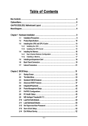
Table of Contents Box Contents ...6 OptionalItems ...6 GA-P35-DS3L/S3L Motherboard Layout 7 Block Diagram ...8 Chapter 1 Hardware Installation 9 1-1 Installation Precautions 9 1-2 Product Specifications 10 1-3 Installing the CPU and CPU Cooler 13 1-3-1 Installing the CPU 13 1-3-2 Installing the ...
Table of Contents Box Contents ...6 OptionalItems ...6 GA-P35-DS3L/S3L Motherboard Layout 7 Block Diagram ...8 Chapter 1 Hardware Installation 9 1-1 Installation Precautions 9 1-2 Product Specifications 10 1-3 Installing the CPU and CPU Cooler 13 1-3-1 Installing the CPU 13 1-3-2 Installing the ...

Manual
Page 7
GA-P35-DS3L/S3L Motherboard Layout KB_MS COAXIAL OPTICAL ATX_12V LGA775 CPU_FAN ATX COM LPT DDRII1 GA-P35-DS3L/S3L R_USB SYS_FAN2 USB LAN F_AUDIO AUDIO SYS_FAN1 PCIE_3 RTL8111B PCIE_16 PCIE_1 SPDIF_O CODEC PCIE_2 SPDIF_I PCI1 PCI2 IT8718 PCI3 CD_IN Intel® P35 FDD DDRII3 DDRII4 DDRII2 PWR_FAN Intel® ICH9 BATTERY CLR_CMOS SATAII0 SATAII1 JMicron 368 SATAII4 BIOS SATAII5 IDE1 F_USB3 F_USB2 F_USB1 CI F_PANEL PWR_LED "*" Only the GA-P35-DS3L adopts All-Solid Capacitor design. - 7 -
GA-P35-DS3L/S3L Motherboard Layout KB_MS COAXIAL OPTICAL ATX_12V LGA775 CPU_FAN ATX COM LPT DDRII1 GA-P35-DS3L/S3L R_USB SYS_FAN2 USB LAN F_AUDIO AUDIO SYS_FAN1 PCIE_3 RTL8111B PCIE_16 PCIE_1 SPDIF_O CODEC PCIE_2 SPDIF_I PCI1 PCI2 IT8718 PCI3 CD_IN Intel® P35 FDD DDRII3 DDRII4 DDRII2 PWR_FAN Intel® ICH9 BATTERY CLR_CMOS SATAII0 SATAII1 JMicron 368 SATAII4 BIOS SATAII5 IDE1 F_USB3 F_USB2 F_USB1 CI F_PANEL PWR_LED "*" Only the GA-P35-DS3L adopts All-Solid Capacitor design. - 7 -
Manual
Page 10
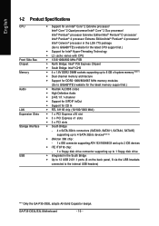
...Intel® Pentium® 4 processor/ Intel® Celeron® processor in the LGA 775 package (Go to GIGABYTE's website for the latest CPU support list.) Š Support for Intel® Hyper-Threading Technology Š L2... 1) Š Dual channel memory architecture Š Support for DDR2 1066/800/667 MHz memory modules (Go to GIGABYTE's website for the latest memory support list.) Š Realtek ALC888 codec Š High Definition Audio Š ...brackets connected to the internal USB headers) "*" Only the GA-P35-DS3L adopts All-Solid Capacitor design. GA-P35-DS3L/S3L Motherboard - 10 -
...Intel® Pentium® 4 processor/ Intel® Celeron® processor in the LGA 775 package (Go to GIGABYTE's website for the latest CPU support list.) Š Support for Intel® Hyper-Threading Technology Š L2... 1) Š Dual channel memory architecture Š Support for DDR2 1066/800/667 MHz memory modules (Go to GIGABYTE's website for the latest memory support list.) Š Realtek ALC888 codec Š High Definition Audio Š ...brackets connected to the internal USB headers) "*" Only the GA-P35-DS3L adopts All-Solid Capacitor design. GA-P35-DS3L/S3L Motherboard - 10 -
Manual
Page 12
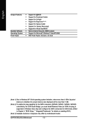
... for AHCI mode. (Refer to Chapter 2, "BIOS Setup," "Integrated Peripherals," for details on enabling AHCI.) (Note 3) Available functions in Easytune may differ by motherboard model. GA-P35-DS3L/S3L Motherboard - 12 -
... for AHCI mode. (Refer to Chapter 2, "BIOS Setup," "Integrated Peripherals," for details on enabling AHCI.) (Note 3) Available functions in Easytune may differ by motherboard model. GA-P35-DS3L/S3L Motherboard - 12 -

Manual
Page 14
... the power outlet to prevent damage to correctly install the CPU into its locked position. Step 3: Lift the metal load plate on the CPU socket. GA-P35-DS3L/S3L Motherboard - 14 - Follow the steps below to the CPU. Align the CPU pin one marking (triangle) with the pin one corner of the CPU socket...
... the power outlet to prevent damage to correctly install the CPU into its locked position. Step 3: Lift the metal load plate on the CPU socket. GA-P35-DS3L/S3L Motherboard - 14 - Follow the steps below to the CPU. Align the CPU pin one marking (triangle) with the pin one corner of the CPU socket...
Manual
Page 16
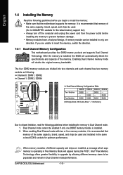
... in only one DDR2 memory module is recommended that the motherboard supports the memory. GA-P35-DS3L/S3L Motherboard - 16 - Intel® Flex Memory Technology offers greater flexibility to upgrade by allowing different memory sizes to be used . (Go to GIGABYTE's website for optimum performance. DS/SS - - The four DDR2 memory sockets are divided into...
... in only one DDR2 memory module is recommended that the motherboard supports the memory. GA-P35-DS3L/S3L Motherboard - 16 - Intel® Flex Memory Technology offers greater flexibility to upgrade by allowing different memory sizes to be used . (Go to GIGABYTE's website for optimum performance. DS/SS - - The four DDR2 memory sockets are divided into...
Manual
Page 18
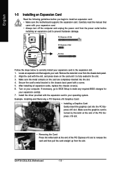
... PCI Slot Follow the steps below to prevent hardware damage. After installing all expansion cards, replace the chassis cover(s). 6. Install the driver provided with a screw. 5. GA-P35-DS3L/S3L Motherboard - 18 - Align the card with your expansion card. • Always turn off the computer and unplug the power cord from the chassis back panel...
... PCI Slot Follow the steps below to prevent hardware damage. After installing all expansion cards, replace the chassis cover(s). 6. Install the driver provided with a screw. 5. GA-P35-DS3L/S3L Motherboard - 18 - Align the card with your expansion card. • Always turn off the computer and unplug the power cord from the chassis back panel...
Manual
Page 20
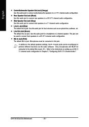
... in a 4/5.1/7.1-channel audio configuration. Line In Jack (Blue) The default line in jack. Microphones must be reconfigured to perform different functions via the audio software. GA-P35-DS3L/S3L Motherboard - 20 - Use this jack. Refer to this audio jack for a headphone or 2-channel speaker. Only microphones still MUST be used to connect rear speakers...
... in a 4/5.1/7.1-channel audio configuration. Line In Jack (Blue) The default line in jack. Microphones must be reconfigured to perform different functions via the audio software. GA-P35-DS3L/S3L Motherboard - 20 - Use this jack. Refer to this audio jack for a headphone or 2-channel speaker. Only microphones still MUST be used to connect rear speakers...

Manual
Page 22
... Definition 3.3V -12V GND PS_ON(soft On/Off) GND GND GND -5V +5V +5V +5V (Only for 2x12-pinATX) GND (Only for 2x12-pin ATX) GA-P35-DS3L/S3L Motherboard - 22 - The 12V power connector mainly supplies power to the power connector in the correct orientation. If a power supply is used that can withstand...
... Definition 3.3V -12V GND PS_ON(soft On/Off) GND GND GND -5V +5V +5V +5V (Only for 2x12-pinATX) GND (Only for 2x12-pin ATX) GA-P35-DS3L/S3L Motherboard - 22 - The 12V power connector mainly supplies power to the power connector in the correct orientation. If a power supply is used that can withstand...
Manual
Page 24
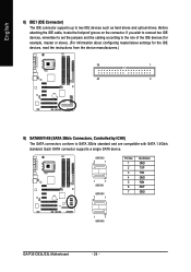
... to SATA 3Gb/s standard and are compatible with SATA 1.5Gb/s standard. SATAII0 7 1 1 7 SATAII1 SATAII4 7 1 Pin No. 1 2 3 4 5 6 7 Definition GND TXP TXN GND RXN RXP GND 1 7 SATAII5 GA-P35-DS3L/S3L Motherboard - 24 - Each SATA connector supports a single SATA device. Before attaching the IDE cable, locate the foolproof groove on the connector. If you wish to...
... to SATA 3Gb/s standard and are compatible with SATA 1.5Gb/s standard. SATAII0 7 1 1 7 SATAII1 SATAII4 7 1 Pin No. 1 2 3 4 5 6 7 Definition GND TXP TXN GND RXN RXP GND 1 7 SATAII5 GA-P35-DS3L/S3L Motherboard - 24 - Each SATA connector supports a single SATA device. Before attaching the IDE cable, locate the foolproof groove on the connector. If you wish to...
Manual
Page 26
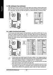
... audio (HD) and AC'97 audio. Make sure the wire assignments of the module connector match the pin assignments of a single plug. Definition Pin No. GA-P35-DS3L/S3L Motherboard - 26 - The LED is on when the system is in S3/S4 sleep state or powered off when the system is operating. The LED...
... audio (HD) and AC'97 audio. Make sure the wire assignments of the module connector match the pin assignments of a single plug. Definition Pin No. GA-P35-DS3L/S3L Motherboard - 26 - The LED is on when the system is in S3/S4 sleep state or powered off when the system is operating. The LED...

Manual
Page 28
... require you wish to connect an HDMI display to the graphics card and have digital audio output from the HDMI display at the same time. GA-P35-DS3L/S3L Motherboard - 28 - For information about connecting the S/PDIF digital audio cable, carefully read the manual for your graphics card if you to use a S/PDIF digital...
... require you wish to connect an HDMI display to the graphics card and have digital audio output from the HDMI display at the same time. GA-P35-DS3L/S3L Motherboard - 28 - For information about connecting the S/PDIF digital audio cable, carefully read the manual for your graphics card if you to use a S/PDIF digital...
Manual
Page 30
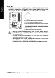
... 5 seconds.) 3. Replace the battery when the battery voltage drops to touch the positive and negative terminals of the battery holder, making them short for one . GA-P35-DS3L/S3L Motherboard - 30 - Danger of explosion if the battery is replaced with an incorrect model. • Contact the place of purchase or local dealer if you...
... 5 seconds.) 3. Replace the battery when the battery voltage drops to touch the positive and negative terminals of the battery holder, making them short for one . GA-P35-DS3L/S3L Motherboard - 30 - Danger of explosion if the battery is replaced with an incorrect model. • Contact the place of purchase or local dealer if you...
Manual
Page 32
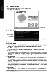
... up arrow key < > or the down arrow key< > to select the first boot device, then press to XpressRecovery2 during the POST. GA-P35-DS3L/S3L Motherboard - 32 - After system restart, the device boot order will directly boot from the device configured in Boot Menu is effective for... P35-DS3L F3a . . . . : BIOS Setup/Q-Flash : XpressRecovery2 : Boot Menu : Qflash 07/12/2007-P35-ICH9-6A79OG0TC-00 Function Keys Function Keys: : POST Screen Press the key to show the BIOS POST ...
... up arrow key < > or the down arrow key< > to select the first boot device, then press to XpressRecovery2 during the POST. GA-P35-DS3L/S3L Motherboard - 32 - After system restart, the device boot order will directly boot from the device configured in Boot Menu is effective for... P35-DS3L F3a . . . . : BIOS Setup/Q-Flash : XpressRecovery2 : Boot Menu : Qflash 07/12/2007-P35-ICH9-6A79OG0TC-00 Function Keys Function Keys: : POST Screen Press the key to show the BIOS POST ...
Manual
Page 34
... Only) ` F11 : Save CMOS to BIOS This function allows you to save the current BIOS settings to erase the default profile name, use this task.) GA-P35-DS3L/S3L Motherboard - 34 -
... Only) ` F11 : Save CMOS to BIOS This function allows you to save the current BIOS settings to erase the default profile name, use this task.) GA-P35-DS3L/S3L Motherboard - 34 -
Manual
Page 36
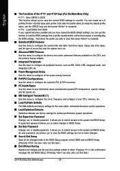
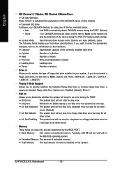
... reserved for all other errors. Options are used, set this channel. All Errors Whenever the BIOS detects a non-fatal error the system boot will stop . GA-P35-DS3L/S3L Motherboard - 36 - Extended IDE Drive Configure your hard drive specifications. Head Number of the currently installed hard drive. Halt on Allows you to determine whether...
... reserved for all other errors. Options are used, set this channel. All Errors Whenever the BIOS detects a non-fatal error the system boot will stop . GA-P35-DS3L/S3L Motherboard - 36 - Extended IDE Drive Configure your hard drive specifications. Head Number of the currently installed hard drive. Halt on Allows you to determine whether...
Manual
Page 38
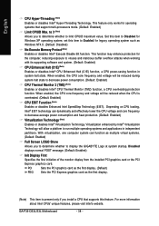
... Halt (C1E) (Note) Enables or disables Intel® CPU Enhanced Halt (C1E) function, a CPU power-saving function in independent partitions. GA-P35-DS3L/S3L Motherboard - 38 - This feature only works for the computer, reducing exposure to decrease average power consumption and heat production. (Default: Enabled) ... install a CPU that support multi-processors mode. (Default: Enabled) Limit CPUID Max. Set this item to display the GIGABYTE Logo at system startup. Virtualization enhanced by Intel® Virtualization Technology will be reduced during system halt state to limit CPUID...
... Halt (C1E) (Note) Enables or disables Intel® CPU Enhanced Halt (C1E) function, a CPU power-saving function in independent partitions. GA-P35-DS3L/S3L Motherboard - 38 - This feature only works for the computer, reducing exposure to decrease average power consumption and heat production. (Default: Enabled) ... install a CPU that support multi-processors mode. (Default: Enabled) Limit CPUID Max. Set this item to display the GIGABYTE Logo at system startup. Virtualization enhanced by Intel® Virtualization Technology will be reduced during system halt state to limit CPUID...

Manual
Page 40
... Cable Is Attached... Link Detected --> 100Mbps Cable Length= 30m Link Detected Displays transmission speed Cable Length Displays the approximate length of the attached LAN cable. GA-P35-DS3L/S3L Motherboard - 40 - English USB Mouse Support Allows USB mouse to be used in MS-DOS. (Default: Disabled) Legacy USB storage detect Determines whether to detect...
... Cable Is Attached... Link Detected --> 100Mbps Cable Length= 30m Link Detected Displays transmission speed Cable Length Displays the approximate length of the attached LAN cable. GA-P35-DS3L/S3L Motherboard - 40 - English USB Mouse Support Allows USB mouse to be used in MS-DOS. (Default: Disabled) Legacy USB storage detect Determines whether to detect...
Manual
Page 42
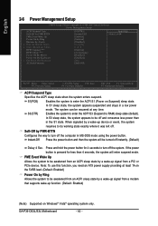
... S3 (Suspend to enter the ACPI S1 (Power on Suspend) sleep state. Press and hold the power button for less than in a low power mode. GA-P35-DS3L/S3L Motherboard - 42 - When signaled by a wake-up signal from a modem that supports wake-up device or event, the system resumes to be resumed at least...
... S3 (Suspend to enter the ACPI S1 (Power on Suspend) sleep state. Press and hold the power button for less than in a low power mode. GA-P35-DS3L/S3L Motherboard - 42 - When signaled by a wake-up signal from a modem that supports wake-up device or event, the system resumes to be resumed at least...

Manual
Page 44
... F7: Optimized Defaults BIOS auto-assigns IRQ to the first PCI slot. (Default) Assigns IRQ 3,4,5,7,9,10,11,12,14,15 to the second PCI slot. GA-P35-DS3L/S3L Motherboard - 44 - BIOS auto-assigns IRQ to the second PCI slot. (Default) Assigns IRQ 3,4,5,7,9,10,11,12,14,15 to the first PCI slot. BIOS...
... F7: Optimized Defaults BIOS auto-assigns IRQ to the first PCI slot. (Default) Assigns IRQ 3,4,5,7,9,10,11,12,14,15 to the second PCI slot. GA-P35-DS3L/S3L Motherboard - 44 - BIOS auto-assigns IRQ to the second PCI slot. (Default) Assigns IRQ 3,4,5,7,9,10,11,12,14,15 to the first PCI slot. BIOS...


