Manual
Page 1
GA-P35-DS3R/ GA-P35-DS3/ GA-P35-S3 LGA775 socket motherboard for Intel® CoreTM processor family/ Intel® Pentium® processor family/Intel® Celeron® processor family User's Manual Rev. 2002 12ME-P35DS3R-2002R
GA-P35-DS3R/ GA-P35-DS3/ GA-P35-S3 LGA775 socket motherboard for Intel® CoreTM processor family/ Intel® Pentium® processor family/Intel® Celeron® processor family User's Manual Rev. 2002 12ME-P35DS3R-2002R
Manual
Page 2
Motherboard GA-P35-DS3R/GA-P35-DS3/GA-P35-S3 Jul. 25, 2007 Motherboard GA-P35-DS3R/GA-P35-DS3/ GA-P35-S3 Jul. 25, 2007
Motherboard GA-P35-DS3R/GA-P35-DS3/GA-P35-S3 Jul. 25, 2007 Motherboard GA-P35-DS3R/GA-P35-DS3/ GA-P35-S3 Jul. 25, 2007
Manual
Page 4
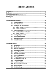
Table of Contents OptionalItems ...6 Box Contents ...6 GA-P35-DS3R/DS3/S3 Motherboard Layout 7 Block Diagram ...8 Chapter 1 Hardware Installation 9 1-1 Installation Precautions 9 1-2 Product Specifications 10 1-3 Installing the CPU and CPU Cooler 13 1-3-1 Installing the CPU 13 1-3-2 ...
Table of Contents OptionalItems ...6 Box Contents ...6 GA-P35-DS3R/DS3/S3 Motherboard Layout 7 Block Diagram ...8 Chapter 1 Hardware Installation 9 1-1 Installation Precautions 9 1-2 Product Specifications 10 1-3 Installing the CPU and CPU Cooler 13 1-3-1 Installing the CPU 13 1-3-2 ...
Manual
Page 5
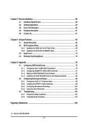
... EasyTune 5 ...73 4-4 Windows Vista ReadyBoost 74 Chapter 5 Appendix ...75 5-1 Configuring SATA Hard Drive(s 75 5-1-1 Configuring Intel® ICH9R SATA Controllers 75 5-1-2 Configuring GIGABYTE SATA2 SATA Controller 81 5-1-3 Making a SATA RAID/AHCI Driver Diskette 87 5-1-4 Installing the SATA RAID/AHCI Driver and Operating System 88 5-2 Configuring Audio Input and... Microphone Recording 100 5-2-4 Using the Sound Recorder 102 5-3 Troubleshooting 103 5-3-1 Frequently Asked Questions 103 5-3-2 Troubleshooting Procedure 104 Regulatory Statements 106 Only for GA-P35-DS3R. - 5 -
... EasyTune 5 ...73 4-4 Windows Vista ReadyBoost 74 Chapter 5 Appendix ...75 5-1 Configuring SATA Hard Drive(s 75 5-1-1 Configuring Intel® ICH9R SATA Controllers 75 5-1-2 Configuring GIGABYTE SATA2 SATA Controller 81 5-1-3 Making a SATA RAID/AHCI Driver Diskette 87 5-1-4 Installing the SATA RAID/AHCI Driver and Operating System 88 5-2 Configuring Audio Input and... Microphone Recording 100 5-2-4 Using the Sound Recorder 102 5-3 Troubleshooting 103 5-3-1 Frequently Asked Questions 103 5-3-2 Troubleshooting Procedure 104 Regulatory Statements 106 Only for GA-P35-DS3R. - 5 -
Manual
Page 6
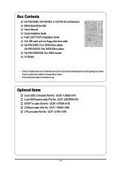
...-32R) LPT port cable (Part No. 12CF1-1LP001-01R) - 6 - The box contents are for reference only. Box Contents GA-P35-DS3R, GA-P35-DS3, or GA-P35-S3 motherboard Motherboard driver disk User's Manual Quick Installation Guide Intel® LGA775 CPU Installation Guide One IDE cable and one floppy disk... drive cable GA-P35-DS3R: Four SATA 3Gb/s cables GA-P35-DS3/S3: Two SATA 3Gb/s cables GA-P35-DS3R/DS3: One SATA bracket I/O Shield • The box contents above are subject to change without notice...
...-32R) LPT port cable (Part No. 12CF1-1LP001-01R) - 6 - The box contents are for reference only. Box Contents GA-P35-DS3R, GA-P35-DS3, or GA-P35-S3 motherboard Motherboard driver disk User's Manual Quick Installation Guide Intel® LGA775 CPU Installation Guide One IDE cable and one floppy disk... drive cable GA-P35-DS3R: Four SATA 3Gb/s cables GA-P35-DS3/S3: Two SATA 3Gb/s cables GA-P35-DS3R/DS3: One SATA bracket I/O Shield • The box contents above are subject to change without notice...
Manual
Page 7
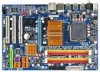
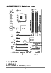
... PCI2 IT8718 CD_IN PCI3 COMA Intel® P35 FDD DDRII3 DDRII4 DDRII2 PWR_FAN BATTERY Intel® ICH9R Intel® ICH9 CLR_CMOS SATAII2 SATAII3 GSATAII0 GIGABYTE SATA2 BIOS GSATAII1 IDE1 SATAII0 SATAII1 SATAII4 SATAII5 F_USB2 F_USB1 CI F_PANEL LPT PWR_LED SYS_FAN2 Only for GA-P35-DS3. "*" Only the GA-P35-DS3R/DS3 adopt All-Solid Capacitor design. - 7 - Only...
... PCI2 IT8718 CD_IN PCI3 COMA Intel® P35 FDD DDRII3 DDRII4 DDRII2 PWR_FAN BATTERY Intel® ICH9R Intel® ICH9 CLR_CMOS SATAII2 SATAII3 GSATAII0 GIGABYTE SATA2 BIOS GSATAII1 IDE1 SATAII0 SATAII1 SATAII4 SATAII5 F_USB2 F_USB1 CI F_PANEL LPT PWR_LED SYS_FAN2 Only for GA-P35-DS3. "*" Only the GA-P35-DS3R/DS3 adopt All-Solid Capacitor design. - 7 - Only...
Manual
Page 8
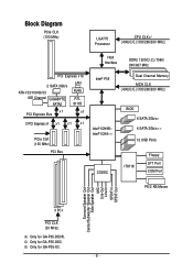
... for GA-P35-S3. - 8 - Only for GA-P35-DS3. Block Diagram PCIe CLK (100 MHz) LGA775 Processor CPU CLK+/(400(O.C.)/333/266/200 MHz) Host Interface DDR2 1200(O.C.)/1066/ 800/667 MHz PCI Express x16 2 SATA 3Gb/s ATA-133/100/66/33 IDE Channel GIGABYTE SATA2 ...LAN RJ45 RTL 8111B x1 PCI Express Bus x1 3 PCI Express x1 x 1 x 1 x 1 PCIe CLK (100 MHz) PCI Bus Intel® P35 Intel® ICH9R Intel® ICH9 CODEC Dual Channel Memory ... MIC Line-Out Line-In SPDIF In SPDIF Out 3 PCI PCI CLK (33 MHz) Only for GA-P35-DS3R.
... for GA-P35-S3. - 8 - Only for GA-P35-DS3. Block Diagram PCIe CLK (100 MHz) LGA775 Processor CPU CLK+/(400(O.C.)/333/266/200 MHz) Host Interface DDR2 1200(O.C.)/1066/ 800/667 MHz PCI Express x16 2 SATA 3Gb/s ATA-133/100/66/33 IDE Channel GIGABYTE SATA2 ...LAN RJ45 RTL 8111B x1 PCI Express Bus x1 3 PCI Express x1 x 1 x 1 x 1 PCIe CLK (100 MHz) PCI Bus Intel® P35 Intel® ICH9R Intel® ICH9 CODEC Dual Channel Memory ... MIC Line-Out Line-In SPDIF In SPDIF Out 3 PCI PCI CLK (33 MHz) Only for GA-P35-DS3R.
Manual
Page 10
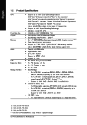
... SATA 3Gb/s devices - 4 x SATA 3Gb/s connectors (SATAII0, SATAII1, SATAII4, SATAII5) supporting up to 4 SATA 3Gb/s devices(Note 2) - GA-P35-DS3R/DS3/S3 Motherboard - 10 - English 1-2 Product Specifications CPU Front Side Bus Chipset Memory Audio LAN Expansion Slots Storage Interface Š Support for an ... codec Š High Definition Audio Š 2/4/5.1/7.1-channel Š Support for S/PDIF In/Out Š Support for GA-P35-DS3R. Only for SATA RAID 0, RAID 1, RAID 5, and RAID 10 Š GIGABYTE SATA2 chip: - 1 x IDE connector supporting ATA-133/100/66/33 and up to 2 IDE devices - 2...
... SATA 3Gb/s devices - 4 x SATA 3Gb/s connectors (SATAII0, SATAII1, SATAII4, SATAII5) supporting up to 4 SATA 3Gb/s devices(Note 2) - GA-P35-DS3R/DS3/S3 Motherboard - 10 - English 1-2 Product Specifications CPU Front Side Bus Chipset Memory Audio LAN Expansion Slots Storage Interface Š Support for an ... codec Š High Definition Audio Š 2/4/5.1/7.1-channel Š Support for S/PDIF In/Out Š Support for GA-P35-DS3R. Only for SATA RAID 0, RAID 1, RAID 5, and RAID 10 Š GIGABYTE SATA2 chip: - 1 x IDE connector supporting ATA-133/100/66/33 and up to 2 IDE devices - 2...
Manual
Page 11
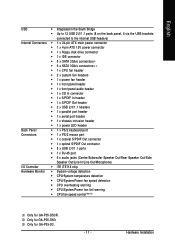
...; CPU/System/Power fan speed detection Š CPU overheating warning Š CPU/System/Power fan fail warning Š CPU fan speed control (Note 3) Only for GA-P35-DS3. Only for GA-P35-DS3R. Hardware Installation Only for GA-P35-S3. - 11 -
...; CPU/System/Power fan speed detection Š CPU overheating warning Š CPU/System/Power fan fail warning Š CPU fan speed control (Note 3) Only for GA-P35-DS3. Only for GA-P35-DS3R. Hardware Installation Only for GA-P35-S3. - 11 -
Manual
Page 12
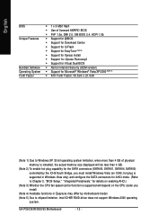
GA-P35-DS3R/DS3/S3 Motherboard - 12 - English BIOS Unique Features Bundled Software Operating System Form Factor Š 1 x 8 Mbit flash Š Use of licensed AWARD BIOS Š PnP 1....
GA-P35-DS3R/DS3/S3 Motherboard - 12 - English BIOS Unique Features Bundled Software Operating System Form Factor Š 1 x 8 Mbit flash Š Use of licensed AWARD BIOS Š PnP 1....
Manual
Page 14
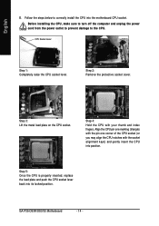
... power cord from the power outlet to prevent damage to correctly install the CPU into the motherboard CPU socket. Step 2: Remove the protective socket cover. GA-P35-DS3R/DS3/S3 Motherboard - 14 - Step 3: Lift the metal load plate on the CPU socket. Step 5: Once the CPU is properly inserted, replace the load plate...
... power cord from the power outlet to prevent damage to correctly install the CPU into the motherboard CPU socket. Step 2: Remove the protective socket cover. GA-P35-DS3R/DS3/S3 Motherboard - 14 - Step 3: Lift the metal load plate on the CPU socket. Step 5: Once the CPU is properly inserted, replace the load plate...
Manual
Page 16
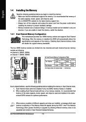
...Make sure that memory of different capacity and chips are installed, a message which says memory is recommended that the motherboard supports the memory. GA-P35-DS3R/DS3/S3 Motherboard - 16 - English 1-4 Installing the Memory Read the following guidelines before installing the memory to prevent hardware damage. •...; Memory modules have a foolproof design. Dual Channel mode cannot be used . (Go to GIGABYTE's website for optimum performance. When enabling Dual Channel mode with two or four memory modules, it is operating in Dual Channel mode...
...Make sure that memory of different capacity and chips are installed, a message which says memory is recommended that the motherboard supports the memory. GA-P35-DS3R/DS3/S3 Motherboard - 16 - English 1-4 Installing the Memory Read the following guidelines before installing the memory to prevent hardware damage. •...; Memory modules have a foolproof design. Dual Channel mode cannot be used . (Go to GIGABYTE's website for optimum performance. When enabling Dual Channel mode with two or four memory modules, it is operating in Dual Channel mode...
Manual
Page 18
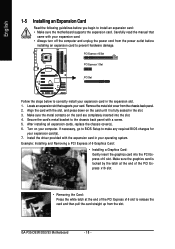
Example: Installing and Removing a PCI Express x16 Graphics Card: • Installing a Graphics Card: Gently insert the graphics card into the slot. 4. GA-P35-DS3R/DS3/S3 Motherboard - 18 - English 1-5 Installing an Expansion Card Read the following guidelines before installing an expansion card to correctly install your expansion card(s). 7. Make ...
Example: Installing and Removing a PCI Express x16 Graphics Card: • Installing a Graphics Card: Gently insert the graphics card into the slot. 4. GA-P35-DS3R/DS3/S3 Motherboard - 18 - English 1-5 Installing an Expansion Card Read the following guidelines before installing an expansion card to correctly install your expansion card(s). 7. Make ...
Manual
Page 19
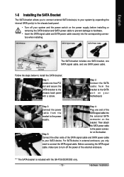
... cable, make sure to hardware. • Insert the SATA signal cable and SATA power cable securely into bracket to the chassis back panel with the GA-P35-DS3R/DS3 only. - 19 - English 1-6 Installing the SATA Bracket The SATA bracket allows you only need to your SATA device. Follow the steps below to install...
... cable, make sure to hardware. • Insert the SATA signal cable and SATA power cable securely into bracket to the chassis back panel with the GA-P35-DS3R/DS3 only. - 19 - English 1-6 Installing the SATA Bracket The SATA bracket allows you only need to your SATA device. Follow the steps below to install...
Manual
Page 20
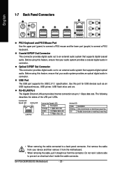
.../2 Mouse Port Use the upper port (green) to connect a PS/2 mouse and the lower port (purple) to prevent an electrical short inside the cable connector. GA-P35-DS3R/DS3/S3 Motherboard - 20 - RJ-45 LAN Port The Gigabit Ethernet LAN port provides Internet connection at up to an external audio system that supports...
.../2 Mouse Port Use the upper port (green) to connect a PS/2 mouse and the lower port (purple) to prevent an electrical short inside the cable connector. GA-P35-DS3R/DS3/S3 Motherboard - 20 - RJ-45 LAN Port The Gigabit Ethernet LAN port provides Internet connection at up to an external audio system that supports...
Manual
Page 22
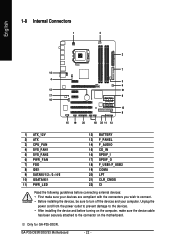
... before connecting external devices: • First make sure the device cable has been securely attached to turn off the devices and your computer. Only for GA-P35-DS3R. English 1-8 Internal Connectors 1 3 2 7 14 4 5 6 12 21 17 9 16 10 8 15 19 20 18 22 11 13 1) ATX_12V 2) ATX 3) CPU_FAN 4) SYS_FAN1 5) SYS_FAN2 6) PWR_FAN 7) FDD 8) IDE1 9) SATAII0... sure your devices are compliant with the connectors you wish to connect. • Before installing the devices, be sure to the connector on the motherboard. GA-P35-DS3R/DS3/S3 Motherboard - 22 -
... before connecting external devices: • First make sure the device cable has been securely attached to turn off the devices and your computer. Only for GA-P35-DS3R. English 1-8 Internal Connectors 1 3 2 7 14 4 5 6 12 21 17 9 16 10 8 15 19 20 18 22 11 13 1) ATX_12V 2) ATX 3) CPU_FAN 4) SYS_FAN1 5) SYS_FAN2 6) PWR_FAN 7) FDD 8) IDE1 9) SATAII0... sure your devices are compliant with the connectors you wish to connect. • Before installing the devices, be sure to the connector on the motherboard. GA-P35-DS3R/DS3/S3 Motherboard - 22 -
Manual
Page 24
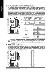
... are : 360 KB, 720 KB, 1.2 MB, 1.44 MB, and 2.88 MB. The black connector wire is used to locate pin 1 of different color. 34 33 GA-P35-DS3R/DS3/S3 Motherboard 2 1 - 24 - English 3/4/5/6) CPU_FAN/SYS_FAN1/SYS_FAN2/PWR_FAN (Fan Headers) The motherboard has a 4-pin CPU fan header (CPU_FAN), a 3-pin system fan header (SYS_FAN1), a 4-pin...
... are : 360 KB, 720 KB, 1.2 MB, 1.44 MB, and 2.88 MB. The black connector wire is used to locate pin 1 of different color. 34 33 GA-P35-DS3R/DS3/S3 Motherboard 2 1 - 24 - English 3/4/5/6) CPU_FAN/SYS_FAN1/SYS_FAN2/PWR_FAN (Fan Headers) The motherboard has a 4-pin CPU fan header (CPU_FAN), a 3-pin system fan header (SYS_FAN1), a 4-pin...

Manual
Page 25
... of hard drives does not have to be an even number. If more than two hard drives are compatible with SATA 1.5Gb/s standard. Only for GA-P35-DS3R. - 25 - Before attaching the IDE cable, locate the foolproof groove on configuring a RAID array.
... of hard drives does not have to be an even number. If more than two hard drives are compatible with SATA 1.5Gb/s standard. Only for GA-P35-DS3R. - 25 - Before attaching the IDE cable, locate the foolproof groove on configuring a RAID array.
Manual
Page 26
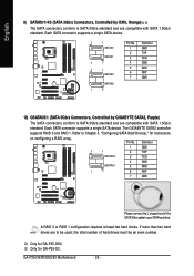
The GIGABYTE SATA2 controller supports RAID 0 and RAID 1. Definition 1 GND 7 1 2 TXP GSATAII0 3 TXN GSATAII1 4 GND 5 RXN 1 7 6 RXP 7 GND ... device. Refer to Chapter 5, "Configuring SATA Hard Drive(s)," for GA-P35-DS3. Pin No. If more than two hard drives are compatible with SATA 1.5Gb/s standard. English 9) SATAII0/1/4/5 (SATA 3Gb/s Connectors, Controlled by GIGABYTE SATA2, Purple) The SATA connectors conform to SATA 3Gb/s standard ... to be used, the total number of the SATA 3Gb/s cable to your SATA hard drive. GA-P35-DS3R/DS3/S3 Motherboard - 26 - Only for...
The GIGABYTE SATA2 controller supports RAID 0 and RAID 1. Definition 1 GND 7 1 2 TXP GSATAII0 3 TXN GSATAII1 4 GND 5 RXN 1 7 6 RXP 7 GND ... device. Refer to Chapter 5, "Configuring SATA Hard Drive(s)," for GA-P35-DS3. Pin No. If more than two hard drives are compatible with SATA 1.5Gb/s standard. English 9) SATAII0/1/4/5 (SATA 3Gb/s Connectors, Controlled by GIGABYTE SATA2, Purple) The SATA connectors conform to SATA 3Gb/s standard ... to be used, the total number of the SATA 3Gb/s cable to your SATA hard drive. GA-P35-DS3R/DS3/S3 Motherboard - 26 - Only for...
Manual
Page 28
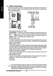
... the power switch, reset switch, speaker and system status indicator on the chassis front panel. Note the positive and negative pins before connecting the cables. GA-P35-DS3R/DS3/S3 Motherboard - 28 - PW+ PWSPEAK+ SPEAK- 2 20 1 19 HD+ HD- The LED is in S3/S4/S5 Off S3/S4 sleep state or powered...
... the power switch, reset switch, speaker and system status indicator on the chassis front panel. Note the positive and negative pins before connecting the cables. GA-P35-DS3R/DS3/S3 Motherboard - 28 - PW+ PWSPEAK+ SPEAK- 2 20 1 19 HD+ HD- The LED is in S3/S4/S5 Off S3/S4 sleep state or powered...

