
Manual
Page 1
GA-P31-S3G LGA775 socket motherboard for Intel® CoreTM processor family/ Intel® Pentium® processor family/Intel® Celeron® processor family User's Manual Rev. 1002 12ME-P31S3G-1002R
GA-P31-S3G LGA775 socket motherboard for Intel® CoreTM processor family/ Intel® Pentium® processor family/Intel® Celeron® processor family User's Manual Rev. 1002 12ME-P31S3G-1002R

Manual
Page 2
Motherboard GA-P31-S3G Sept. 21, 2007 Motherboard GA-P31-S3G Sept. 21, 2007
Motherboard GA-P31-S3G Sept. 21, 2007 Motherboard GA-P31-S3G Sept. 21, 2007

Manual
Page 4
Table of Contents Box Contents ...6 OptionalItems ...6 GA-P31-S3G Motherboard Layout 7 Block Diagram ...8 Chapter 1 Hardware Installation 9 1-1 Installation Precautions 9 1-2 Product Specifications 10 1-3 Installing the CPU and CPU Cooler 13 1-3-1 Installing the CPU 13 1-3-2 Installing the ...
Table of Contents Box Contents ...6 OptionalItems ...6 GA-P31-S3G Motherboard Layout 7 Block Diagram ...8 Chapter 1 Hardware Installation 9 1-1 Installation Precautions 9 1-2 Product Specifications 10 1-3 Installing the CPU and CPU Cooler 13 1-3-1 Installing the CPU 13 1-3-2 Installing the ...
Manual
Page 6
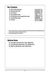
Optional Items 2-port USB 2.0 bracket (Part No. 12CR1-1UB030-51R) 2-port SATA power cable (Part No. 12CF1-2SERPW-01R) S/PDIF out cable (Part No. 12CR1-1SPOUT-02R) - 6 - Box Contents GA-P31-S3G motherboard Motherboard driver disk User's Manual Quick Installation Guide One IDE cable and one floppy disk drive cable Two SATA 3Gb/s cables I/O Shield • The box contents above are subject to change without notice. • The motherboard image is for reference only and the actual items shall depend on product package you obtain. The box contents are for reference only.
Optional Items 2-port USB 2.0 bracket (Part No. 12CR1-1UB030-51R) 2-port SATA power cable (Part No. 12CF1-2SERPW-01R) S/PDIF out cable (Part No. 12CR1-1SPOUT-02R) - 6 - Box Contents GA-P31-S3G motherboard Motherboard driver disk User's Manual Quick Installation Guide One IDE cable and one floppy disk drive cable Two SATA 3Gb/s cables I/O Shield • The box contents above are subject to change without notice. • The motherboard image is for reference only and the actual items shall depend on product package you obtain. The box contents are for reference only.

Manual
Page 7
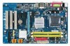
GA-P31-S3G Motherboard Layout KB_MS ATX_12V LGA775 CPU_FAN COMA LPT GA-P31-S3G ATX USB R_USB LAN CD_IN SPDIF_O AUDIO F_AUDIO RTL8111B IT8718 CODEC PCIE_1 PCIE_16 PCIE_2 PCIE_3 PCI1 PCI2 PCI3 Intel® P31 IDE SATAII2 Intel® ICH7 SATAII3 BAT CLR_CMOS F_USB1 F_USB2 SATAII0 MBIOS FDD SYS_FAN CI SATAII1 DDRII1 DDRII2 PWR_LED F_PANEL - 7 -
GA-P31-S3G Motherboard Layout KB_MS ATX_12V LGA775 CPU_FAN COMA LPT GA-P31-S3G ATX USB R_USB LAN CD_IN SPDIF_O AUDIO F_AUDIO RTL8111B IT8718 CODEC PCIE_1 PCIE_16 PCIE_2 PCIE_3 PCI1 PCI2 PCI3 Intel® P31 IDE SATAII2 Intel® ICH7 SATAII3 BAT CLR_CMOS F_USB1 F_USB2 SATAII0 MBIOS FDD SYS_FAN CI SATAII1 DDRII1 DDRII2 PWR_LED F_PANEL - 7 -

Manual
Page 8
Block Diagram PCIe CLK (100 MHz) LGA775 Processor Host Interface PCI Express x16 Intel® P31 3 PCI Express x1 CPU CLK+/(333/266/200 MHz) DDR2 1066/800/667 MHz Dual Channel Memory MCH CLK (333/266/200 MHz) PCIe CLK (100 MHz) x1 x1 x1 PCI Express Bus RTL8111B RJ45 LAN PCI Bus Intel® ICH7 CODEC BIOS ATA-100/66/33 IDE Channel 4 SATA 3Gb/s 8 USB Ports IT8718 Floppy LPT Port COM Port PS/2 KB/Mouse MIC (Center/Subwoofer Speaker Out) Line-Out (Front Speaker Out) Line-In (Rear Speaker Out) SPDIF Out 3 PCI PCI CLK (33 MHz) - 8 -
Block Diagram PCIe CLK (100 MHz) LGA775 Processor Host Interface PCI Express x16 Intel® P31 3 PCI Express x1 CPU CLK+/(333/266/200 MHz) DDR2 1066/800/667 MHz Dual Channel Memory MCH CLK (333/266/200 MHz) PCIe CLK (100 MHz) x1 x1 x1 PCI Express Bus RTL8111B RJ45 LAN PCI Bus Intel® ICH7 CODEC BIOS ATA-100/66/33 IDE Channel 4 SATA 3Gb/s 8 USB Ports IT8718 Floppy LPT Port COM Port PS/2 KB/Mouse MIC (Center/Subwoofer Speaker Out) Line-Out (Front Speaker Out) Line-In (Rear Speaker Out) SPDIF Out 3 PCI PCI CLK (33 MHz) - 8 -

Manual
Page 10
...Edition/Intel® Pentium® 4 processor/ Intel® Celeron® processor in the LGA 775 package (Go to GIGABYTE's website for the latest CPU support list.) Š L2 cache varies with CPU Š 1333/1066/800 MHz FSB Š...of system memory Š Dual channel memory architecture Š Support for DDR2 1066/800/667 MHz memory modules (Go to GIGABYTE's website for the latest memory support list.) Š Realtek ALC662 codec Š High Definition Audio Š 2/4/5.1-channel ...on the back panel, 4 via the USB brackets connected to the internal USB headers) GA-P31-S3G Motherboard - 10 -
...Edition/Intel® Pentium® 4 processor/ Intel® Celeron® processor in the LGA 775 package (Go to GIGABYTE's website for the latest CPU support list.) Š L2 cache varies with CPU Š 1333/1066/800 MHz FSB Š...of system memory Š Dual channel memory architecture Š Support for DDR2 1066/800/667 MHz memory modules (Go to GIGABYTE's website for the latest memory support list.) Š Realtek ALC662 codec Š High Definition Audio Š 2/4/5.1-channel ...on the back panel, 4 via the USB brackets connected to the internal USB headers) GA-P31-S3G Motherboard - 10 -

Manual
Page 12
GA-P31-S3G Motherboard - 12 - Unique Features Bundled Software Operating System Form Factor Š Support for @BIOS Š Support for Download Center Š Support for Q-Flash Š Support for EasyTune (Note) Š Support for Xpress Install Š Support for Xpress Recovery2 Š Support for Virtual Dual BIOS Š Norton Internet Security (OEM version) Š Support for Microsoft® Windows® Vista/XP/2000 Š ATX Form Factor; 30.5cm x 19.4cm (Note) Available functions in Easytune may differ by motherboard model.
GA-P31-S3G Motherboard - 12 - Unique Features Bundled Software Operating System Form Factor Š Support for @BIOS Š Support for Download Center Š Support for Q-Flash Š Support for EasyTune (Note) Š Support for Xpress Install Š Support for Xpress Recovery2 Š Support for Virtual Dual BIOS Š Norton Internet Security (OEM version) Š Support for Microsoft® Windows® Vista/XP/2000 Š ATX Form Factor; 30.5cm x 19.4cm (Note) Available functions in Easytune may differ by motherboard model.

Manual
Page 14
... with the socket alignment keys) and gently insert the CPU into the motherboard CPU socket. CPU Socket Lever Step 1: Completely raise the CPU socket lever. GA-P31-S3G Motherboard - 14 - Follow the steps below to the CPU.
... with the socket alignment keys) and gently insert the CPU into the motherboard CPU socket. CPU Socket Lever Step 1: Completely raise the CPU socket lever. GA-P31-S3G Motherboard - 14 - Follow the steps below to the CPU.

Manual
Page 16
...to insert the memory, switch the direction. 1-4-1 Dual Channel Memory Configuration This motherboard provides two DDR2 memory sockets and supports Dual Channel Technology. GA-P31-S3G Motherboard - 16 - If you begin to install the memory: • Make sure that memory of the memory. Enabling Dual Channel memory mode...one DDR2 memory module is installed, the BIOS will double the original memory bandwidth. Dual Channel mode cannot be used . (Go to GIGABYTE's website for the latest memory support list.) • Always turn off the computer and unplug the power cord from the power outlet ...
...to insert the memory, switch the direction. 1-4-1 Dual Channel Memory Configuration This motherboard provides two DDR2 memory sockets and supports Dual Channel Technology. GA-P31-S3G Motherboard - 16 - If you begin to install the memory: • Make sure that memory of the memory. Enabling Dual Channel memory mode...one DDR2 memory module is installed, the BIOS will double the original memory bandwidth. Dual Channel mode cannot be used . (Go to GIGABYTE's website for the latest memory support list.) • Always turn off the computer and unplug the power cord from the power outlet ...

Manual
Page 18
... Graphics Card: • Installing a Graphics Card: Gently push down on the top edge of the card until it is fully seated in the expansion slot. 1. GA-P31-S3G Motherboard - 18 - Install the driver provided with a screw. 5. Secure the card's metal bracket to install an expansion card: • Make sure the motherboard supports the...
... Graphics Card: • Installing a Graphics Card: Gently push down on the top edge of the card until it is fully seated in the expansion slot. 1. GA-P31-S3G Motherboard - 18 - Install the driver provided with a screw. 5. Secure the card's metal bracket to install an expansion card: • Make sure the motherboard supports the...

Manual
Page 20
Line Out Jack (Green) The default line out jack. Mic In Jack (Pink) The default Mic in jack. GA-P31-S3G Motherboard - 20 - This jack can be connected to this jack. Refer to connect front speakers in a 4/5.1-channel audio configuration. Use this audio jack for line in Chapter 5, "Configuring 2/4/5.1-Channel Audio." Microphones must be used to the instructions on setting up a 2/4/5.1-channel audio configuration in devices such as an optical drive, walkman, etc. Use this audio jack for a headphone or 2-channel speaker. Line In Jack (Blue) The default line in jack.
Line Out Jack (Green) The default line out jack. Mic In Jack (Pink) The default Mic in jack. GA-P31-S3G Motherboard - 20 - This jack can be connected to this jack. Refer to connect front speakers in a 4/5.1-channel audio configuration. Use this audio jack for line in Chapter 5, "Configuring 2/4/5.1-Channel Audio." Microphones must be used to the instructions on setting up a 2/4/5.1-channel audio configuration in devices such as an optical drive, walkman, etc. Use this audio jack for a headphone or 2-channel speaker. Line In Jack (Blue) The default line in jack.

Manual
Page 22
... 3.3V -12V GND PS_ON(soft On/Off) GND GND GND -5V +5V +5V +5V (Only for 2x12-pin ATX) GND (Only for 2x12-pin ATX) GA-P31-S3G Motherboard - 22 - If the 12V power connector is not connected, the computer will not start. • To meet expansion requirements, it is compatible with power...
... 3.3V -12V GND PS_ON(soft On/Off) GND GND GND -5V +5V +5V +5V (Only for 2x12-pin ATX) GND (Only for 2x12-pin ATX) GA-P31-S3G Motherboard - 22 - If the 12V power connector is not connected, the computer will not start. • To meet expansion requirements, it is compatible with power...
Manual
Page 24
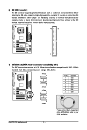
Each SATA connector supports a single SATA device. SATAII2 7 1 1 7 SATAII3 SATAII0 7 1 Pin No. 1 2 3 4 5 6 7 Definition GND TXP TXN GND RXN RXP GND GA-P31-S3G Motherboard 1 7 SATAII1 - 24 - 6) IDE (IDE Connector) The IDE connector supports up to your SATA hard drive. Please connect the L-shaped end of the IDE devices (...
Each SATA connector supports a single SATA device. SATAII2 7 1 1 7 SATAII3 SATAII0 7 1 Pin No. 1 2 3 4 5 6 7 Definition GND TXP TXN GND RXN RXP GND GA-P31-S3G Motherboard 1 7 SATAII1 - 24 - 6) IDE (IDE Connector) The IDE connector supports up to your SATA hard drive. Please connect the L-shaped end of the IDE devices (...

Manual
Page 26
...," for information about beep codes. • HD (IDE Hard Drive Activity LED, Blue) Connects to the hard drive activity LED on the chassis front panel. GA-P31-S3G Motherboard - 26 - Speaker Connector Power Switch Message LED/ Power/ Sleep LED SPEAK- 20 19 SPEAK+ PWPW+ MSGMSG+ 21 NC RES+ RESHD- The LED keeps blinking...
...," for information about beep codes. • HD (IDE Hard Drive Activity LED, Blue) Connects to the hard drive activity LED on the chassis front panel. GA-P31-S3G Motherboard - 26 - Speaker Connector Power Switch Message LED/ Power/ Sleep LED SPEAK- 20 19 SPEAK+ PWPW+ MSGMSG+ 21 NC RES+ RESHD- The LED keeps blinking...

Manual
Page 28
... the CMOS values and before turning on the two pins to temporarily short the two pins or use a metal object like a screwdriver to factory defaults. GA-P31-S3G Motherboard - 28 - 13) F_USB1/F_USB2 (USB Headers) The headers conform to Chapter 2, "BIOS Setup," for a few seconds. Each USB header can provide two USB ports...
... the CMOS values and before turning on the two pins to temporarily short the two pins or use a metal object like a screwdriver to factory defaults. GA-P31-S3G Motherboard - 28 - 13) F_USB1/F_USB2 (USB Headers) The headers conform to Chapter 2, "BIOS Setup," for a few seconds. Each USB header can provide two USB ports...
Manual
Page 32
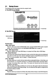
... Startup Screen The following screens may appear when the computer boots. Motherboard Model BIOS Version Intel P31 BIOS for P31-S3G E11 . . . . : BIOS Setup/Q-Flash : XpressRecovery2 : Boot Menu : Qflash 09/12/2007-P31-ICH7-6A89OG08C-00 Function Keys Function Keys: : POST Screen Press the key to show the...directly boot from the device configured in BIOS Setup. : Xpress Recovery2 If you to set the first boot device without having to accept. GA-P31-S3G Motherboard - 32 - For more information, refer to Chapter 4, "Xpress Recovery2." : Boot Menu Boot Menu allows you have ever entered ...
... Startup Screen The following screens may appear when the computer boots. Motherboard Model BIOS Version Intel P31 BIOS for P31-S3G E11 . . . . : BIOS Setup/Q-Flash : XpressRecovery2 : Boot Menu : Qflash 09/12/2007-P31-ICH7-6A89OG08C-00 Function Keys Function Keys: : POST Screen Press the key to show the...directly boot from the device configured in BIOS Setup. : Xpress Recovery2 If you to set the first boot device without having to accept. GA-P31-S3G Motherboard - 32 - For more information, refer to Chapter 4, "Xpress Recovery2." : Boot Menu Boot Menu allows you have ever entered ...

Manual
Page 34
... Status Use this menu to see information about autodetected system/CPU temperature, system voltage and fan speed, etc. „ MB Intelligent Tweaker(M.I.T.) Use this task.) GA-P31-S3G Motherboard - 34 -
... Status Use this menu to see information about autodetected system/CPU temperature, system voltage and fan speed, etc. „ MB Intelligent Tweaker(M.I.T.) Use this task.) GA-P31-S3G Motherboard - 34 -

Manual
Page 36
... to the information on the hard drive. All Errors Whenever the BIOS detects a non-fatal error the system boot will stop for all other errors. GA-P31-S3G Motherboard - 36 - Head Number of the currently installed hard drive. Precomp Write precompensation cylinder. Landing Zone Landing zone. Capacity Approximate capacity of heads. Floppy 3 Mode...
... to the information on the hard drive. All Errors Whenever the BIOS detects a non-fatal error the system boot will stop for all other errors. GA-P31-S3G Motherboard - 36 - Head Number of the currently installed hard drive. Precomp Write precompensation cylinder. Landing Zone Landing zone. Capacity Approximate capacity of heads. Floppy 3 Mode...

Manual
Page 38
... voltage will be reduced when the CPU is present only if you install a CPU that supports this item to display the GIGABYTE Logo at system startup. With virtualization, one CPU core. GA-P31-S3G Motherboard - 38 - CPU Multi-Threading (Note) Allows you to determine whether to enable all CPU cores and multi-threading capability...
... voltage will be reduced when the CPU is present only if you install a CPU that supports this item to display the GIGABYTE Logo at system startup. With virtualization, one CPU core. GA-P31-S3G Motherboard - 38 - CPU Multi-Threading (Note) Allows you to determine whether to enable all CPU cores and multi-threading capability...
