
Manual
Page 3
...manual may be made by GIGA-BYTE TECHNOLOGY CO., LTD as the exclu- All rights reserved. Documentation Classifications In order to GIGABYTE UNITED INC. by copyright laws and is exclusively licensed to assist in any form or by any means without prior notice....on/from the Support\Motherboard\Technology Guide page on your motherboard revision before updating motherboard BIOS, drivers, or when looking for technical information. sive global distributor of GIGABYTE. GIGABYTE UNITED INC. Changes to the specifications and features in this manual are legally registered ...
...manual may be made by GIGA-BYTE TECHNOLOGY CO., LTD as the exclu- All rights reserved. Documentation Classifications In order to GIGABYTE UNITED INC. by copyright laws and is exclusively licensed to assist in any form or by any means without prior notice....on/from the Support\Motherboard\Technology Guide page on your motherboard revision before updating motherboard BIOS, drivers, or when looking for technical information. sive global distributor of GIGABYTE. GIGABYTE UNITED INC. Changes to the specifications and features in this manual are legally registered ...

Manual
Page 4
Table of Contents Box Contents ...6 OptionalItems ...6 GA-P31-S3G Motherboard Layout 7 Block Diagram ...8 Chapter 1 Hardware Installation 9 1-1 Installation Precautions 9 1-2 Product Specifications 10 1-3 Installing the CPU and CPU Cooler 13 ... Memory 17 1-5 Installing an Expansion Card 18 1-6 Back Panel Connectors 19 1-7 Internal Connectors 21 Chapter 2 BIOS Setup 31 2-1 Startup Screen 32 2-2 The Main Menu 33 2-3 Standard CMOS Features 35 2-4 Advanced BIOS Features 37 2-5 IntegratedPeripherals 39 2-6 Power Management Setup 42 2-7 PnP/PCI Configurations 44 2-8 PC Health Status ...
Table of Contents Box Contents ...6 OptionalItems ...6 GA-P31-S3G Motherboard Layout 7 Block Diagram ...8 Chapter 1 Hardware Installation 9 1-1 Installation Precautions 9 1-2 Product Specifications 10 1-3 Installing the CPU and CPU Cooler 13 ... Memory 17 1-5 Installing an Expansion Card 18 1-6 Back Panel Connectors 19 1-7 Internal Connectors 21 Chapter 2 BIOS Setup 31 2-1 Startup Screen 32 2-2 The Main Menu 33 2-3 Standard CMOS Features 35 2-4 Advanced BIOS Features 37 2-5 IntegratedPeripherals 39 2-6 Power Management Setup 42 2-7 PnP/PCI Configurations 44 2-8 PC Health Status ...

Manual
Page 5
... 54 3-3 Driver CD Information 54 3-4 Hardware Information 55 3-5 Contact Us ...55 Chapter 4 Unique Features 57 4-1 Xpress Recovery2 57 4-2 BIOS Update Utilities 62 4-2-1 Updating the BIOS with the Q-Flash Utility 62 4-2-2 Updating the BIOS with the @BIOS Utility 65 4-3 EasyTune 5 Pro 67 4-4 Windows Vista ReadyBoost 68 Chapter 5 Appendix ...69 5-1 ConfiguringAudio Input and Output 69 5-1-1 Configuring...
... 54 3-3 Driver CD Information 54 3-4 Hardware Information 55 3-5 Contact Us ...55 Chapter 4 Unique Features 57 4-1 Xpress Recovery2 57 4-2 BIOS Update Utilities 62 4-2-1 Updating the BIOS with the Q-Flash Utility 62 4-2-2 Updating the BIOS with the @BIOS Utility 65 4-3 EasyTune 5 Pro 67 4-4 Windows Vista ReadyBoost 68 Chapter 5 Appendix ...69 5-1 ConfiguringAudio Input and Output 69 5-1-1 Configuring...

Manual
Page 8
Block Diagram PCIe CLK (100 MHz) LGA775 Processor Host Interface PCI Express x16 Intel® P31 3 PCI Express x1 CPU CLK+/(333/266/200 MHz) DDR2 1066/800/667 MHz Dual Channel Memory MCH CLK (333/266/200 MHz) PCIe CLK (100 MHz) x1 x1 x1 PCI Express Bus RTL8111B RJ45 LAN PCI Bus Intel® ICH7 CODEC BIOS ATA-100/66/33 IDE Channel 4 SATA 3Gb/s 8 USB Ports IT8718 Floppy LPT Port COM Port PS/2 KB/Mouse MIC (Center/Subwoofer Speaker Out) Line-Out (Front Speaker Out) Line-In (Rear Speaker Out) SPDIF Out 3 PCI PCI CLK (33 MHz) - 8 -
Block Diagram PCIe CLK (100 MHz) LGA775 Processor Host Interface PCI Express x16 Intel® P31 3 PCI Express x1 CPU CLK+/(333/266/200 MHz) DDR2 1066/800/667 MHz Dual Channel Memory MCH CLK (333/266/200 MHz) PCIe CLK (100 MHz) x1 x1 x1 PCI Express Bus RTL8111B RJ45 LAN PCI Bus Intel® ICH7 CODEC BIOS ATA-100/66/33 IDE Channel 4 SATA 3Gb/s 8 USB Ports IT8718 Floppy LPT Port COM Port PS/2 KB/Mouse MIC (Center/Subwoofer Speaker Out) Line-Out (Front Speaker Out) Line-In (Rear Speaker Out) SPDIF Out 3 PCI PCI CLK (33 MHz) - 8 -

Manual
Page 11
... Š CPU temperature detection Š CPU/System fan speed detection Š CPU overheating warning Š CPU/System fan fail warning Š CPU fan speed control BIOS Š 1 x 4 Mbit flash Š Use of licensed AWARD...
... Š CPU temperature detection Š CPU/System fan speed detection Š CPU overheating warning Š CPU/System fan fail warning Š CPU fan speed control BIOS Š 1 x 4 Mbit flash Š Use of licensed AWARD...

Manual
Page 12
Unique Features Bundled Software Operating System Form Factor Š Support for @BIOS Š Support for Download Center Š Support for Q-Flash Š Support for EasyTune (Note) Š Support for Xpress Install Š Support for Xpress Recovery2 Š Support for Virtual Dual BIOS Š Norton Internet Security (OEM version) Š Support for Microsoft® Windows® Vista/XP/2000 Š ATX Form Factor; 30.5cm x 19.4cm (Note) Available functions in Easytune may differ by motherboard model. GA-P31-S3G Motherboard - 12 -
Unique Features Bundled Software Operating System Form Factor Š Support for @BIOS Š Support for Download Center Š Support for Q-Flash Š Support for EasyTune (Note) Š Support for Xpress Install Š Support for Xpress Recovery2 Š Support for Virtual Dual BIOS Š Norton Internet Security (OEM version) Š Support for Microsoft® Windows® Vista/XP/2000 Š ATX Form Factor; 30.5cm x 19.4cm (Note) Available functions in Easytune may differ by motherboard model. GA-P31-S3G Motherboard - 12 -

Manual
Page 16
... recommended that memory of the same capacity, brand, speed, and chips be installed in Dual Channel mode. 1. GA-P31-S3G Motherboard - 16 - A memory module can be used . (Go to GIGABYTE's website for the latest memory support list.) • Always turn off the computer and unplug the power cord from...specifications and capacity of the same capacity, brand, speed, and chips be enabled if only one DDR2 memory module is installed, the BIOS will double the original memory bandwidth. It is recommended that the motherboard supports the memory. If you begin to insert the memory, switch...
... recommended that memory of the same capacity, brand, speed, and chips be installed in Dual Channel mode. 1. GA-P31-S3G Motherboard - 16 - A memory module can be used . (Go to GIGABYTE's website for the latest memory support list.) • Always turn off the computer and unplug the power cord from...specifications and capacity of the same capacity, brand, speed, and chips be enabled if only one DDR2 memory module is installed, the BIOS will double the original memory bandwidth. It is recommended that the motherboard supports the memory. If you begin to insert the memory, switch...

Manual
Page 18
...does not rock. • Removing the Card: Gently push back on the lever on the card are completely inserted into the PCI Express x16 slot. GA-P31-S3G Motherboard - 18 - Locate an expansion slot that came with the slot, and press down on your operating system. Remove the metal slot cover from... the slot. If necessary, go to BIOS Setup to make any required BIOS changes for your expansion card. • Always turn off the computer and unplug the power cord from the power outlet before you...
...does not rock. • Removing the Card: Gently push back on the lever on the card are completely inserted into the PCI Express x16 slot. GA-P31-S3G Motherboard - 18 - Locate an expansion slot that came with the slot, and press down on your operating system. Remove the metal slot cover from... the slot. If necessary, go to BIOS Setup to make any required BIOS changes for your expansion card. • Always turn off the computer and unplug the power cord from the power outlet before you...

Manual
Page 26
...The S0 On LED is on when the system is detected, the BIOS may issue beeps in different patterns to the speaker on the chassis front panel. You may differ by issuing a beep code. If a problem is operating. GA-P31-S3G Motherboard - 26 - Note the positive and negative pins before connecting ...): Connects to the hard drive activity LED on the chassis front panel. When connecting your system using the power switch (refer to Chapter 2, "BIOS Setup," "Power Management Setup," for information about beep codes. • HD (IDE Hard Drive Activity LED, Blue) Connects to the reset switch...
...The S0 On LED is on when the system is detected, the BIOS may issue beeps in different patterns to the speaker on the chassis front panel. You may differ by issuing a beep code. If a problem is operating. GA-P31-S3G Motherboard - 26 - Note the positive and negative pins before connecting ...): Connects to the hard drive activity LED on the chassis front panel. When connecting your system using the power switch (refer to Chapter 2, "BIOS Setup," "Power Management Setup," for information about beep codes. • HD (IDE Hard Drive Activity LED, Blue) Connects to the reset switch...

Manual
Page 28
...computer and unplug the power cord from the jumper. 13) F_USB1/F_USB2 (USB Headers) The headers conform to touch the two pins for BIOS configurations). To clear the CMOS values, place a jumper cap on your computer and unplug the power cord from the power outlet to ...the USB header. • Prior to installing the USB bracket, be sure to clear the CMOS values (e.g. GA-P31-S3G Motherboard - 28 - date information and BIOS configurations) and reset the CMOS values to Chapter 2, "BIOS Setup," for a few seconds. Failure to do so may cause damage to the motherboard. • After ...
...computer and unplug the power cord from the jumper. 13) F_USB1/F_USB2 (USB Headers) The headers conform to touch the two pins for BIOS configurations). To clear the CMOS values, place a jumper cap on your computer and unplug the power cord from the power outlet to ...the USB header. • Prior to installing the USB bracket, be sure to clear the CMOS values (e.g. GA-P31-S3G Motherboard - 28 - date information and BIOS configurations) and reset the CMOS values to Chapter 2, "BIOS Setup," for a few seconds. Failure to do so may cause damage to the motherboard. • After ...

Manual
Page 29
This function requires a chassis with local environmental regulations. - 29 - Replace the battery when the battery voltage drops to keep the values (such as BIOS configurations, date, and time information) in the CMOS when the computer is replaced with an incorrect model. • Contact the place of purchase or local ...
This function requires a chassis with local environmental regulations. - 29 - Replace the battery when the battery voltage drops to keep the values (such as BIOS configurations, date, and time information) in the CMOS when the computer is replaced with an incorrect model. • Contact the place of purchase or local ...

Manual
Page 31
... the Power-On Self-Test (POST) during the POST. To upgrade the BIOS, use either the GIGABYTE Q-Flash or @BIOS utility. • Q-Flash allows the user to quickly and easily upgrade or back up BIOS without entering the operating system. • @BIOS is turned off, the battery on the motherboard supplies the necessary power to...
... the Power-On Self-Test (POST) during the POST. To upgrade the BIOS, use either the GIGABYTE Q-Flash or @BIOS utility. • Q-Flash allows the user to quickly and easily upgrade or back up BIOS without entering the operating system. • @BIOS is turned off, the battery on the motherboard supplies the necessary power to...
Manual
Page 32
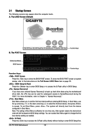
... Press the key to enter BIOS Setup or to show the BIOS POST screen at system startup, refer to access the Q-Flash utility directly without entering BIOS Setup. The LOGO Screen (Default) :POST Screen :BIOS Setup/Q-Flash :XpressRecovery2 :Boot Menu :Qflash Function Keys B. GA-P31-S3G Motherboard - 32 - The POST Screen Award Modular BIOS v6.00PG, An Energy...
... Press the key to enter BIOS Setup or to show the BIOS POST screen at system startup, refer to access the Q-Flash utility directly without entering BIOS Setup. The LOGO Screen (Default) :POST Screen :BIOS Setup/Q-Flash :XpressRecovery2 :Boot Menu :Qflash Function Keys B. GA-P31-S3G Motherboard - 32 - The POST Screen Award Modular BIOS v6.00PG, An Energy...

Manual
Page 33
... + to access more advanced options. • When the system is not stable as shown below) appears on the bottom line of the Main Menu. BIOS Setup Program Function Keys Move the selection bar to select an item Execute command or enter the submenu Main Menu: Exit the... settings for the current submenus Access the Q-Flash utility Display system information Save all the changes and exit the BIOS Setup program Save CMOS to BIOS F12: Load CMOS from BIOS Main Menu Help The onscreen description of a highlighted setup option is displayed on the screen. Use arrow keys to move ...
... + to access more advanced options. • When the system is not stable as shown below) appears on the bottom line of the Main Menu. BIOS Setup Program Function Keys Move the selection bar to select an item Execute command or enter the submenu Main Menu: Exit the... settings for the current submenus Access the Q-Flash utility Display system information Save all the changes and exit the BIOS Setup program Save CMOS to BIOS F12: Load CMOS from BIOS Main Menu Help The onscreen description of a highlighted setup option is displayed on the screen. Use arrow keys to move ...

Manual
Page 34
...and date, hard drive types, floppy disk drive types, and the type of your system becomes unstable and you have loaded the BIOS default settings, you to restrict access to a profile. An user password only allows you wish to load, then press to complete...BIOS Features Use this menu to configure the device boot order, advanced features available on the CPU, and the primary display adapter. „ Integrated Peripherals Use this menu to configure all peripheral devices, such as IDE, SATA, USB, integrated audio, and integrated LAN, etc. „ Power Management Setup Use this task.) GA-P31-S3G...
...and date, hard drive types, floppy disk drive types, and the type of your system becomes unstable and you have loaded the BIOS default settings, you to restrict access to a profile. An user password only allows you wish to load, then press to complete...BIOS Features Use this menu to configure the device boot order, advanced features available on the CPU, and the primary display adapter. „ Integrated Peripherals Use this menu to configure all peripheral devices, such as IDE, SATA, USB, integrated audio, and integrated LAN, etc. „ Power Management Setup Use this task.) GA-P31-S3G...

Manual
Page 35
...use the up arrow or down arrow key to set to autodetect the parameters of the three methods below : • Auto • None Lets BIOS automatically detect IDE/SATA devices during the POST for faster system startup. The date format is 13:0:0. IDE Channel 2, 3 Master/Slave IDE Auto-Detection... Press to CHS. Extended IDE Drive Configure your IDE/SATA devices by using one of the two methods below : • Auto Lets BIOS automatically detect IDE/SATA devices during the POST. (Default) • None • Manual If no IDE/SATA devices are used , set this channel...
...use the up arrow or down arrow key to set to autodetect the parameters of the three methods below : • Auto • None Lets BIOS automatically detect IDE/SATA devices during the POST for faster system startup. The date format is 13:0:0. IDE Channel 2, 3 Master/Slave IDE Auto-Detection... Press to CHS. Extended IDE Drive Configure your IDE/SATA devices by using one of the two methods below : • Auto Lets BIOS automatically detect IDE/SATA devices during the POST. (Default) • None • Manual If no IDE/SATA devices are used , set this channel...

Manual
Page 36
... errors. Typically, 640 KB will not stop for any error. GA-P31-S3G Motherboard - 36 - If you do not install a floppy disk drive, set this item to None. Landing Zone Landing zone. Options are determined by the BIOS POST. Base Memory Also called conventional memory. If you wish to... and are : None, 360K/5.25", 1.2M/5.25", 720K/3.5", 1.44M/3.5", 2.88M/3.5". Extended Memory The amount of sectors. All Errors Whenever the BIOS detects a non-fatal error the system boot will stop for an error during the POST. All, But Keyboard The system boot will not stop ...
... errors. Typically, 640 KB will not stop for any error. GA-P31-S3G Motherboard - 36 - If you do not install a floppy disk drive, set this item to None. Landing Zone Landing zone. Options are determined by the BIOS POST. Base Memory Also called conventional memory. If you wish to... and are : None, 360K/5.25", 1.2M/5.25", 720K/3.5", 1.44M/3.5", 2.88M/3.5". Extended Memory The amount of sectors. All Errors Whenever the BIOS detects a non-fatal error the system boot will stop for an error during the POST. All, But Keyboard The system boot will not stop ...

Manual
Page 37
...or only when you install a CPU that supports this item, set the password(s) under the Set Supervisor/User Password item in the BIOS Main Menu. First/Second/Third Boot Device Specifies the boot order from the installed hard drives. Options are: Floppy, LS120, Hard... of loading the operating system from the available devices. BIOS Setup Password Check Specifies whether a password is present only if you enter BIOS Setup. 2-4 Advanced BIOS Features CMOS Setup Utility-Copyright (C) 1984-2007 Award Software Advanced BIOS Features ` Hard Disk Boot Priority First Boot Device [...
...or only when you install a CPU that supports this item, set the password(s) under the Set Supervisor/User Password item in the BIOS Main Menu. First/Second/Third Boot Device Specifies the boot order from the installed hard drives. Options are: Floppy, LS120, Hard... of loading the operating system from the available devices. BIOS Setup Password Check Specifies whether a password is present only if you enter BIOS Setup. 2-4 Advanced BIOS Features CMOS Setup Utility-Copyright (C) 1984-2007 Award Software Advanced BIOS Features ` Hard Disk Boot Priority First Boot Device [...

Manual
Page 39
...mode as needed. (Default) Combined Sets all SATA devices to Combined or Enhanced mode. When PATA IDE Set to is set to settings. Auto Lets BIOS set to operate in PATA mode and disables the integrated IDE controller. PATA IDE Set to This item is configurable only if the On-Chip...Non-Combined is dependent on the On-Chip SATA Mode and PATA IDE Set to Combined. Sets all SATA devices to Ch. 0 Master/Slave. - 39 - BIOS Setup Ch.0 Master/Slave Sets the IDE channels to Ch. 0 Master/Slave. (Default) Ch.1 Master/Slave Sets the IDE channels to be automatically set SATA...
...mode as needed. (Default) Combined Sets all SATA devices to Combined or Enhanced mode. When PATA IDE Set to is set to settings. Auto Lets BIOS set to operate in PATA mode and disables the integrated IDE controller. PATA IDE Set to This item is configurable only if the On-Chip...Non-Combined is dependent on the On-Chip SATA Mode and PATA IDE Set to Combined. Sets all SATA devices to Ch. 0 Master/Slave. - 39 - BIOS Setup Ch.0 Master/Slave Sets the IDE channels to Ch. 0 Master/Slave. (Default) Ch.1 Master/Slave Sets the IDE channels to be automatically set SATA...

Manual
Page 41
...), EPP (Enhanced Parallel Port), ECP (Extended Capabilities Port), ECP+EPP. - 41 - When a Cable Problem Occurs... Options are : 378/IRQ7 (default), 278/IRQ5, 3BC/IRQ7, Disabled. BIOS Setup Note: The Gigabit hub will appear: Start detecting at about 1.6m on Pair 1-2. If a cable problem occurs on the LAN cable connected to the...
...), EPP (Enhanced Parallel Port), ECP (Extended Capabilities Port), ECP+EPP. - 41 - When a Cable Problem Occurs... Options are : 378/IRQ7 (default), 278/IRQ5, 3BC/IRQ7, Disabled. BIOS Setup Note: The Gigabit hub will appear: Start detecting at about 1.6m on Pair 1-2. If a cable problem occurs on the LAN cable connected to the...


