
Manual
Page 11
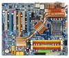
... power connector Š 1 4-pin PCIe 12V power connector Š 1 floppy connector Š 1 IDE connector Š 10 SATA 3Gb/s connectors Š 1 CPU fan connector Š 1 system fan connector Š 1 power fan connector Š 1 North Bridge fan connector Š 1 front panel connector Š 1 front audio connector Š 1 CD In connector Š 1 S/PDIF In connector Š 3 USB 2.0/1.1 connectors...
... power connector Š 1 4-pin PCIe 12V power connector Š 1 floppy connector Š 1 IDE connector Š 10 SATA 3Gb/s connectors Š 1 CPU fan connector Š 1 system fan connector Š 1 power fan connector Š 1 North Bridge fan connector Š 1 front panel connector Š 1 front audio connector Š 1 CD In connector Š 1 S/PDIF In connector Š 3 USB 2.0/1.1 connectors...
Manual
Page 14
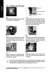
... sure the push pins aim to the pin hole on the motherboard.Pressing down the push pins diagonally. The CPU cooler may adhere to the CPU as the picture, the installation is complete. GA-N680SLI-DQ6 Motherboard - 14 - If the push pin is inserted as a result of hardening of the heat paste. English ... of arrow sign on the male push pin doesn't face inwards before installation. (This instruction is only for Intel boxed fan) Fig. 3 Place the CPU cooler atop the CPU and make sure the Male and Female push pin are joined closely. (for heat dissipation or using extreme care when removing...
... sure the push pins aim to the pin hole on the motherboard.Pressing down the push pins diagonally. The CPU cooler may adhere to the CPU as the picture, the installation is complete. GA-N680SLI-DQ6 Motherboard - 14 - If the push pin is inserted as a result of hardening of the heat paste. English ... of arrow sign on the male push pin doesn't face inwards before installation. (This instruction is only for Intel boxed fan) Fig. 3 Place the CPU cooler atop the CPU and make sure the Male and Female push pin are joined closely. (for heat dissipation or using extreme care when removing...
Manual
Page 25
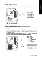
... A red power connector wire indicates a positive connection and requires a +12V power voltage. Hardware Installation Remember to connect the CPU/system/power fan cable to the CPU_FAN/SYS_FAN/PWR_FAN connector to the onboard PCI Express x16 slot. English 3) PCIE_12V (Power Connector) This power... connector provides extra power to prevent CPU damage or system hanging caused by overheating. 1 CPU_FAN / SYS_FAN CPU_FAN / SYS_FAN : Pin...
... A red power connector wire indicates a positive connection and requires a +12V power voltage. Hardware Installation Remember to connect the CPU/system/power fan cable to the CPU_FAN/SYS_FAN/PWR_FAN connector to the onboard PCI Express x16 slot. English 3) PCIE_12V (Power Connector) This power... connector provides extra power to prevent CPU damage or system hanging caused by overheating. 1 CPU_FAN / SYS_FAN CPU_FAN / SYS_FAN : Pin...

Manual
Page 52
... at next boot. Disabled Disable this function. (Default value) CPU/SYSTEM/POWER FAN Fail Warning Disabled Disable CPU/system/power fan fail warning function. (Default value) Enabled Enable CPU/system/power fan fail warning function. If the case is closed, Case Opened will show "Yes." GA-N680SLI-DQ6 Motherboard - 52 - If you want to reset Case Opened value, enable...
... at next boot. Disabled Disable this function. (Default value) CPU/SYSTEM/POWER FAN Fail Warning Disabled Disable CPU/system/power fan fail warning function. (Default value) Enabled Enable CPU/system/power fan fail warning function. If the case is closed, Case Opened will show "Yes." GA-N680SLI-DQ6 Motherboard - 52 - If you want to reset Case Opened value, enable...
Manual
Page 53
... to PWM when you use a CPU fan with a 3-pin fan power cable. Set to Voltage when you use a CPU fan with a 4-pin fan power cable. ing on system temperature. English CPU Smart FAN Control(Note) Disabled Enabled Disable this function is enabled, CPU fan will run at different speed depending on CPU temperature. System Smart FAN Control Disabled Disable this function. (Default...
... to PWM when you use a CPU fan with a 3-pin fan power cable. Set to Voltage when you use a CPU fan with a 4-pin fan power cable. ing on system temperature. English CPU Smart FAN Control(Note) Disabled Enabled Disable this function is enabled, CPU fan will run at different speed depending on CPU temperature. System Smart FAN Control Disabled Disable this function. (Default...

Manual
Page 65
...button Toggles between Easy and Advance Mode Display panel of both CPU cooling fan and North-Bridge Chipset cooling fan, 4) PC health for monitoring system status.(Note) User Interface Overview Button / Display 1. GIGABYTE Logo 10. Appendix Overclocking 2. and M.I .A. Featuring several... powerful yet easy to use tools such as 1) Overclocking for managing fan speed control of CPU frequency Shows the current functions status Log on to GIGABYTE website Display EasyTuneTM 5 Help file Quit or Minimize EasyTuneTM 5 software (Note) EasyTune 5 functions...
...button Toggles between Easy and Advance Mode Display panel of both CPU cooling fan and North-Bridge Chipset cooling fan, 4) PC health for monitoring system status.(Note) User Interface Overview Button / Display 1. GIGABYTE Logo 10. Appendix Overclocking 2. and M.I .A. Featuring several... powerful yet easy to use tools such as 1) Overclocking for managing fan speed control of CPU frequency Shows the current functions status Log on to GIGABYTE website Display EasyTuneTM 5 Help file Quit or Minimize EasyTuneTM 5 software (Note) EasyTune 5 functions...


