Manual
Page 4
Table of Contents ItemChecklist ...6 OptionalAccessories ...6 GA-N680SLI-DQ6 Motherboard Layout 7 Block Diagram ...8 Chapter 1 Hardware Installation 9 1-1 Considerations Prior to Installation 9 1-2 Feature Summary 10 1-3 Installation of the ... (Scalable Link Interface) Configuration 19 1-8 I/O Back Panel Introduction 22 1-9 Connectors Introduction 23 Chapter 2 BIOS Setup 35 The Main Menu (For example: BIOS Ver. : FAa 37 2-1 Standard CMOS Features 39 2-2 Advanced BIOS Features 41 2-3 IntegratedPeripherals 43 2-4 Power Management Setup 49 2-5 PnP/PCI Configurations 51 2-6 PC Health ...
Table of Contents ItemChecklist ...6 OptionalAccessories ...6 GA-N680SLI-DQ6 Motherboard Layout 7 Block Diagram ...8 Chapter 1 Hardware Installation 9 1-1 Considerations Prior to Installation 9 1-2 Feature Summary 10 1-3 Installation of the ... (Scalable Link Interface) Configuration 19 1-8 I/O Back Panel Introduction 22 1-9 Connectors Introduction 23 Chapter 2 BIOS Setup 35 The Main Menu (For example: BIOS Ver. : FAa 37 2-1 Standard CMOS Features 39 2-2 Advanced BIOS Features 41 2-3 IntegratedPeripherals 43 2-4 Power Management Setup 49 2-5 PnP/PCI Configurations 51 2-6 PC Health ...
Manual
Page 5
... 4-1-6 Windows Vista ReadyBoost 104 4-2 Troubleshooting 105 - 5 - GIGABYTE SATA2 Controller 85 4-1-5 2- / 4- / 6- / 8- Chapter 3 Drivers Installation 61 3-1 Install Chipset Drivers 61 3-2 SoftwareApplications 62 3-3 Driver CD Information 62 3-4 Hardware Information 63 3-5 Contact Us ...63 Chapter 4 Appendix 65 4-1 Unique Software Utilities 65 4-1-1 EasyTune 5 Introduction 65 4-1-2 Xpress Recovery2 Introduction 66 4-1-3 Flash BIOS Method Introduction 68 4-1-4 Configuring SATA Hard...
... 4-1-6 Windows Vista ReadyBoost 104 4-2 Troubleshooting 105 - 5 - GIGABYTE SATA2 Controller 85 4-1-5 2- / 4- / 6- / 8- Chapter 3 Drivers Installation 61 3-1 Install Chipset Drivers 61 3-2 SoftwareApplications 62 3-3 Driver CD Information 62 3-4 Hardware Information 63 3-5 Contact Us ...63 Chapter 4 Appendix 65 4-1 Unique Software Utilities 65 4-1-1 EasyTune 5 Introduction 65 4-1-2 Xpress Recovery2 Introduction 66 4-1-3 Flash BIOS Method Introduction 68 4-1-4 Configuring SATA Hard...

Manual
Page 8
... 88E8052 88E8056 x1 x1 nVIDIA® nForce 680i SLI Northbridge Dual Channel Memory 1 PCI Express x1 PCIe CLK (100 MHz) PCI Express Bus 4 SATA 3Gb/s GIGABYTE SATA2 x 2 6 SATA 3Gb/s PCI Bus LAN1 LAN2 RJ45 RJ45 Marvell 88E1116 x 2 nVIDIA® nForce 680i SLI Southbridge ATA33/66/100/133 IDE Channel ...Floppy LPC BUS IT8718 LPT Port COM Port TSB43AB23 CODEC PS/2 KB/Mouse 3 PCI PCI CLK (33 MHz) 10 USB Ports Dual BIOS PCI Express x8 PCI Express x16 3 IEEE1394a Surround Speaker Out Center/Subwoofer Speaker Out Side Speaker Out MIC Line-Out Line-In SPDIF In SPDIF...
... 88E8052 88E8056 x1 x1 nVIDIA® nForce 680i SLI Northbridge Dual Channel Memory 1 PCI Express x1 PCIe CLK (100 MHz) PCI Express Bus 4 SATA 3Gb/s GIGABYTE SATA2 x 2 6 SATA 3Gb/s PCI Bus LAN1 LAN2 RJ45 RJ45 Marvell 88E1116 x 2 nVIDIA® nForce 680i SLI Southbridge ATA33/66/100/133 IDE Channel ...Floppy LPC BUS IT8718 LPT Port COM Port TSB43AB23 CODEC PS/2 KB/Mouse 3 PCI PCI CLK (33 MHz) 10 USB Ports Dual BIOS PCI Express x8 PCI Express x16 3 IEEE1394a Surround Speaker Out Center/Subwoofer Speaker Out Side Speaker Out MIC Line-Out Line-In SPDIF In SPDIF...

Manual
Page 11
... detection Š CPU / System / Power fan speed detection Š CPU warning temperature Š CPU / System / Power fan failure warning Š CPU / System smart fan control BIOS Š 2 4 Mbit flash ROM Š Use of licensed AWARD...
... detection Š CPU / System / Power fan speed detection Š CPU warning temperature Š CPU / System / Power fan failure warning Š CPU / System smart fan control BIOS Š 2 4 Mbit flash ROM Š Use of licensed AWARD...
Manual
Page 12
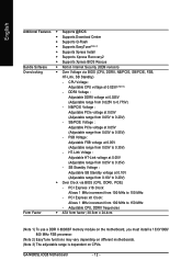
...voltage at 0.05V (Adjustable range from 0.05V to 0.20V) - PCI Express x8 Clock: Allows 1 MHz increment from 100 MHz to 0.35V) - GA-N680SLI-DQ6 Motherboard - 12 - NB/PCIE Voltage : Adjustable PCIe voltage at 0.10V (Adjustable range from 0.05V to 150 MHz - FSB Voltage : Adjustable FSB ... to 0.775V) - HT-Link Voltage : Adjustable HT-Link voltage at 0.05V (Adjustable range from 0.025V to 0.20V) Š Over Clock via BIOS (CPU, DDRII, NB/PCIE, SB/PCIE, FSB, HT-Link, SB Standby) - Adjustable CPU, DDRII frequencies Form Factor Š ATX form factor;...
...voltage at 0.05V (Adjustable range from 0.05V to 0.20V) - PCI Express x8 Clock: Allows 1 MHz increment from 100 MHz to 0.35V) - GA-N680SLI-DQ6 Motherboard - 12 - NB/PCIE Voltage : Adjustable PCIe voltage at 0.10V (Adjustable range from 0.05V to 150 MHz - FSB Voltage : Adjustable FSB ... to 0.775V) - HT-Link Voltage : Adjustable HT-Link voltage at 0.05V (Adjustable range from 0.025V to 0.20V) Š Over Clock via BIOS (CPU, DDRII, NB/PCIE, SB/PCIE, FSB, HT-Link, SB Standby) - Adjustable CPU, DDRII frequencies Form Factor Š ATX form factor;...
Manual
Page 13
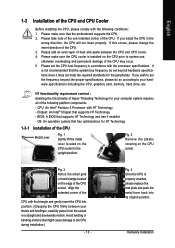
... 4 Processor with HT Technology - OS: An operation system that might cause damage to system use, otherwise overheating and permanent damage of the CPU may occur. 5. BIOS: A BIOS that supports HT Technology - Please add an even layer of the CPU. 3. Please take note of the one indented corner of the CPU. Chipset: An...
... 4 Processor with HT Technology - OS: An operation system that might cause damage to system use, otherwise overheating and permanent damage of the CPU may occur. 5. BIOS: A BIOS that supports HT Technology - Please add an even layer of the CPU. 3. Please take note of the one indented corner of the CPU. Chipset: An...

Manual
Page 15
... - A memory module can be used can only fit in one direction. If you wish to prevent hardware damage. 3. The motherboard supports DDRII memory modules, whereby BIOS will automatically detect memory capacity and specifications.
... - A memory module can be used can only fit in one direction. If you wish to prevent hardware damage. 3. The motherboard supports DDRII memory modules, whereby BIOS will automatically detect memory capacity and specifications.

Manual
Page 17
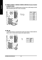
... expansion slot in the operating system. Make sure the metal contacts on the computer, if necessary, configure required settings for the expansion card in system BIOS Setup. 8. The motherboard includes a PCIE_12V power connector, which provides extra power to uninstall the VGA card on the card. Power on the card are fully...
... expansion slot in the operating system. Make sure the metal contacts on the computer, if necessary, configure required settings for the expansion card in system BIOS Setup. 8. The motherboard includes a PCIE_12V power connector, which provides extra power to uninstall the VGA card on the card. Power on the card are fully...
Manual
Page 27
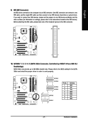
... 300 MB/s transfer rate. Hardware Installation One IDE connector can provide up to two IDE devices (hard drive or optical drive). Please refer to the BIOS setting for information on settings, please refer to the computer via an IDE connector. English 9) IDE (IDE Connector) An IDE device connects to the instructions...
... 300 MB/s transfer rate. Hardware Installation One IDE connector can provide up to two IDE devices (hard drive or optical drive). Please refer to the BIOS setting for information on settings, please refer to the computer via an IDE connector. English 9) IDE (IDE Connector) An IDE device connects to the instructions...
Manual
Page 28
... 11) GSATAII1-0 / GSATAII1-1 / GSATAII2-0 / GSATAII2-1 (SATA 3Gb/s Connector, Controlled by GIGABYTE SATA2) SATA 3Gb/s can provide up to indicate whether the system is connected with the system power indicator to 300 MB/s transfer rate. GA-N680SLI-DQ6 Motherboard - 28 - Please refer to the BIOS setting for the SATA 3Gb/s and install the proper driver in...
... 11) GSATAII1-0 / GSATAII1-1 / GSATAII2-0 / GSATAII2-1 (SATA 3Gb/s Connector, Controlled by GIGABYTE SATA2) SATA 3Gb/s can provide up to indicate whether the system is connected with the system power indicator to 300 MB/s transfer rate. GA-N680SLI-DQ6 Motherboard - 28 - Please refer to the BIOS setting for the SATA 3Gb/s and install the proper driver in...
Manual
Page 33
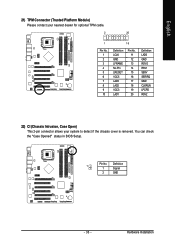
Hardware Installation Definition 1 Signal 2 GND - 33 - English 21) TPM Connector (Trusted Platform Module) Please contact your nearest dealer for optional TPM cable. 2 20 1 Pin No. 1 2 3 4 5 6 7 8 9 10 19 Definition LCLK GND LFRAME No Pin LRESET VCC5 LAD3 LAD2 VCC3 LAD1 Pin No. 11 12 13 14 15 16 17 18 19 20 Definition LAD0 GND RSVO RSV1 SB3V SERIRQ GND CLKRUN LPCPD RSV2 22) CI (Chassis Intrusion, Case Open) This 2-pin connector allows your system to detect if the chassis cover is removed. You can check the "Case Opened" status in BIOS Setup. 1 Pin No.
Hardware Installation Definition 1 Signal 2 GND - 33 - English 21) TPM Connector (Trusted Platform Module) Please contact your nearest dealer for optional TPM cable. 2 20 1 Pin No. 1 2 3 4 5 6 7 8 9 10 19 Definition LCLK GND LFRAME No Pin LRESET VCC5 LAD3 LAD2 VCC3 LAD1 Pin No. 11 12 13 14 15 16 17 18 19 20 Definition LAD0 GND RSVO RSV1 SB3V SERIRQ GND CLKRUN LPCPD RSV2 22) CI (Chassis Intrusion, Case Open) This 2-pin connector allows your system to detect if the chassis cover is removed. You can check the "Case Opened" status in BIOS Setup. 1 Pin No.
Manual
Page 35
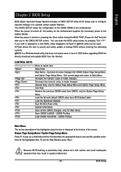
...that does not require users to boot to DOS before upgrading BIOS but directly download and update BIOS from BIOS - Status Page Setup Menu / Option Page Setup Menu Press F1 to a new BIOS, either Gigabyte's Q-Flash or @BIOS utility can enter the BIOS setup screen by pressing "Ctrl + F1". When the ...power is turned on, pressing the button during the BIOS POST (Power-On Self Test) will take you wish to upgrade...
...that does not require users to boot to DOS before upgrading BIOS but directly download and update BIOS from BIOS - Status Page Setup Menu / Option Page Setup Menu Press F1 to a new BIOS, either Gigabyte's Q-Flash or @BIOS utility can enter the BIOS setup screen by pressing "Ctrl + F1". When the ...power is turned on, pressing the button during the BIOS POST (Power-On Self Test) will take you wish to upgrade...
Manual
Page 36
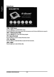
GA-N680SLI-DQ6 Motherboard - 36 - English Startup Screen: :POST Screen :BIOS Setup/Dual BIOS :XpressRecovery2 :Boot Menu : Qflash : POST Screen Press the TAB key to see BIOS POST screen. (To show the BIOS POST screen at system startup, refer to the instructions on the Full Screen LOGO Show item on page 42.) : BIOS Setup/Dual BIOS... Press the DELETE key to enter BIOS Setup program. : Xpress Recovery2 Press the F9 key to enter the Xpress Recovery2 screen. : Boot Menu ...
GA-N680SLI-DQ6 Motherboard - 36 - English Startup Screen: :POST Screen :BIOS Setup/Dual BIOS :XpressRecovery2 :Boot Menu : Qflash : POST Screen Press the TAB key to see BIOS POST screen. (To show the BIOS POST screen at system startup, refer to the instructions on the Full Screen LOGO Show item on page 42.) : BIOS Setup/Dual BIOS... Press the DELETE key to enter BIOS Setup program. : Xpress Recovery2 Press the F9 key to enter the Xpress Recovery2 screen. : Boot Menu ...

Manual
Page 37
... the hassles of resetting the CMOS configurations. „ Standard CMOS Features This setup page includes all the items in standard compatible BIOS. „ Advanced BIOS Features This setup page includes all the items of Award special enhanced features. „ Integrated Peripherals This setup page includes all onboard... on the screen. Use arrow keys to select among the items and press to accept or enter the sub-menu. BIOS Setting Recovery F11 : Save CMOS to BIOS This function allows you want, press "Ctrl+F1" to access advanced options. 2. CMOS Setup Utility-Copyright (C) 1984-2007...
... the hassles of resetting the CMOS configurations. „ Standard CMOS Features This setup page includes all the items in standard compatible BIOS. „ Advanced BIOS Features This setup page includes all the items of Award special enhanced features. „ Integrated Peripherals This setup page includes all onboard... on the screen. Use arrow keys to select among the items and press to accept or enter the sub-menu. BIOS Setting Recovery F11 : Save CMOS to BIOS This function allows you want, press "Ctrl+F1" to access advanced options. 2. CMOS Setup Utility-Copyright (C) 1984-2007...
Manual
Page 39
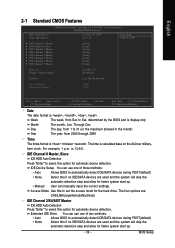
...day, from 1 to automatically detect IDE/SATA devices during POST(default) • None Select this option for automatic device detection. is , , , . BIOS Setup English 2-1 Standard CMOS Features Date (mm:dd:yy) Time (hh:mm:ss) CMOS Setup Utility-Copyright (C) 1984-2007 Award Software Standard CMOS Features Fri... Setup. Through Dec. The time is display-only Month The month, Jan. You can use one of two methods: • Auto Allows BIOS to 31 (or the maximum allowed in the month) Year The year, from Sun to set the access mode for faster system start up ...
...day, from 1 to automatically detect IDE/SATA devices during POST(default) • None Select this option for automatic device detection. is , , , . BIOS Setup English 2-1 Standard CMOS Features Date (mm:dd:yy) Time (hh:mm:ss) CMOS Setup Utility-Copyright (C) 1984-2007 Award Software Standard CMOS Features Fri... Setup. Through Dec. The time is display-only Month The month, Jan. You can use one of two methods: • Auto Allows BIOS to 31 (or the maximum allowed in the month) Year The year, from Sun to set the access mode for faster system start up ...
Manual
Page 40
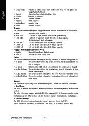
... system boot will stop for systems with 640 K or more memory installed on The category determines whether the computer will be prompted. GA-N680SLI-DQ6 Motherboard - 40 - English Access Mode Capacity Cylinder Head Use this to set the access mode for Japan Area) Disabled Drive A ..., 3.5" 3.5 inch double-sided drive; 1.44 M byte capacity. 2.88M, 3.5" 3.5 inch double-sided drive; 2.88 M byte capacity. All Errors Whenever the BIOS detects a non-fatal error the system will stop for all other errors. Memory The category is display-only which is determined by POST (Power On...
... system boot will stop for systems with 640 K or more memory installed on The category determines whether the computer will be prompted. GA-N680SLI-DQ6 Motherboard - 40 - English Access Mode Capacity Cylinder Head Use this to set the access mode for Japan Area) Disabled Drive A ..., 3.5" 3.5 inch double-sided drive; 1.44 M byte capacity. 2.88M, 3.5" 3.5 inch double-sided drive; 2.88 M byte capacity. All Errors Whenever the BIOS detects a non-fatal error the system will stop for all other errors. Memory The category is display-only which is determined by POST (Power On...
Manual
Page 41
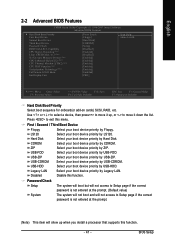
... Third Boot Device Floppy Select your boot device priority by Floppy. LS120 Select your boot device priority by LS120. Disabled Disable this menu. BIOS Setup Press to move it up when you install a processor that supports this function. - 41 - Hard Disk Select your boot device ... by USB-ZIP. USB-CDROM Select your boot device priority by USB-CDROM. English 2-2 Advanced BIOS Features CMOS Setup Utility-Copyright (C) 1984-2007 Award Software Advanced BIOS Features Hard Disk Boot Priority First Boot Device Second Boot Device Third Boot Device Password Check HDD ...
... Third Boot Device Floppy Select your boot device priority by Floppy. LS120 Select your boot device priority by LS120. Disabled Disable this menu. BIOS Setup Press to move it up when you install a processor that supports this function. - 41 - Hard Disk Select your boot device ... by USB-ZIP. USB-CDROM Select your boot device priority by USB-CDROM. English 2-2 Advanced BIOS Features CMOS Setup Utility-Copyright (C) 1984-2007 Award Software Advanced BIOS Features Hard Disk Boot Priority First Boot Device Second Boot Device Third Boot Device Password Check HDD ...
Manual
Page 42
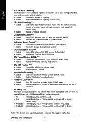
...read/write errors and to PCI Express VGA card (the PCIE_16_2 slot). (Note) This item will show up when you wish to see BIOS POST screen, set this function. capability. (Default value) CPU Hyper-Threading (Note) Enabled Enable CPU Hyper Threading Feature. to 3 ...value) No-Execute Memory Protect (Note) Enabled Disabled Enable No-Execute Memory Protect function. (Default value) Disable No-Execute Memory Protect function. GA-N680SLI-DQ6 Motherboard - 42 - Disable HDD S.M.A.R.T. Full Screen LOGO Show Enabled Disabled Show full screen logo at system startup. (Default value) Disable this...
...read/write errors and to PCI Express VGA card (the PCIE_16_2 slot). (Note) This item will show up when you wish to see BIOS POST screen, set this function. capability. (Default value) CPU Hyper-Threading (Note) Enabled Enable CPU Hyper Threading Feature. to 3 ...value) No-Execute Memory Protect (Note) Enabled Disabled Enable No-Execute Memory Protect function. (Default value) Disable No-Execute Memory Protect function. GA-N680SLI-DQ6 Motherboard - 42 - Disable HDD S.M.A.R.T. Full Screen LOGO Show Enabled Disabled Show full screen logo at system startup. (Default value) Disable this...
Manual
Page 43
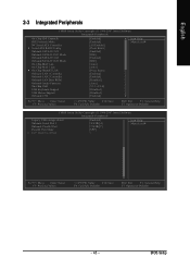
... Level : Move Enter: Select F5: Previous Values +/-/PU/PD: Value F10: Save F6: Fail-Safe Defaults ESC: Exit F1: General Help F7: Optimized Defaults - 43 - BIOS Setup
... Level : Move Enter: Select F5: Previous Values +/-/PU/PD: Value F10: Save F6: Fail-Safe Defaults ESC: Exit F1: General Help F7: Optimized Defaults - 43 - BIOS Setup

Manual
Page 45
...of the SATA-II Ctrl1 (GSATAII1-0 / GSATAII1-1) ports controlled by the te Gigabyte SATA2 controller. For more details about AHCI, please visit Intel's website. For more details about AHCI, please visit Intel's website. BIOS Setup English NV SATA 3 Primary RAID Enabled Enable NV SATA 3 primary RAID... function allows users to decide the operating mode of the SATA-II Ctrl2 (GSATAII2-0 / GSATAII2-1) ports controlled by the Gigabyte SATA2 controller. On-Chip MAC Lan (LAN1) Auto Auto-detect onboard LAN chip function. (Default value) Disabled Disable onboard LAN chip function...
...of the SATA-II Ctrl1 (GSATAII1-0 / GSATAII1-1) ports controlled by the te Gigabyte SATA2 controller. For more details about AHCI, please visit Intel's website. For more details about AHCI, please visit Intel's website. BIOS Setup English NV SATA 3 Primary RAID Enabled Enable NV SATA 3 primary RAID... function allows users to decide the operating mode of the SATA-II Ctrl2 (GSATAII2-0 / GSATAII2-1) ports controlled by the Gigabyte SATA2 controller. On-Chip MAC Lan (LAN1) Auto Auto-detect onboard LAN chip function. (Default value) Disabled Disable onboard LAN chip function...


