Manual
Page 4
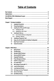
Table of Contents Box Contents ...6 OptionalItems ...6 GA-N650SLI-DS4L Motherboard Layout 7 Block Diagram ...8 Chapter 1 Hardware Installation 9 1-1 Installation Precautions 9 1-2 Product Specifications 10 1-3 Installing the CPU and CPU Cooler 13 1-3-1 Installing the CPU 13 1-3-2 Installing the CPU Cooler 15 1-4 Installing the Memory 16 1-4-1 Dual Channel Memory Configuration 16 1-4-2 Installing a Memory 17 1-5 Installing an Expansion Card 18 1-6 Setup of an...
Table of Contents Box Contents ...6 OptionalItems ...6 GA-N650SLI-DS4L Motherboard Layout 7 Block Diagram ...8 Chapter 1 Hardware Installation 9 1-1 Installation Precautions 9 1-2 Product Specifications 10 1-3 Installing the CPU and CPU Cooler 13 1-3-1 Installing the CPU 13 1-3-2 Installing the CPU Cooler 15 1-4 Installing the Memory 16 1-4-1 Dual Channel Memory Configuration 16 1-4-2 Installing a Memory 17 1-5 Installing an Expansion Card 18 1-6 Setup of an...
Manual
Page 8
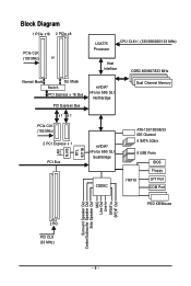
... DDR2 800/667/533 MHz Normal Mode SLI Mode Switch PCI Express x 16 Bus PCI Express Bus nVIDIA® nForce 650i SLI Northbridge Dual Channel Memory x1 x1 PCIe CLK (100 MHz) 2 PCI Express x 1 PCI Bus LAN RJ45 RTL 8211B nVIDIA® nForce 650i SLI Southbridge CODEC ATA-133/100/66...
... DDR2 800/667/533 MHz Normal Mode SLI Mode Switch PCI Express x 16 Bus PCI Express Bus nVIDIA® nForce 650i SLI Northbridge Dual Channel Memory x1 x1 PCIe CLK (100 MHz) 2 PCI Express x 1 PCI Bus LAN RJ45 RTL 8211B nVIDIA® nForce 650i SLI Southbridge CODEC ATA-133/100/66...
Manual
Page 9
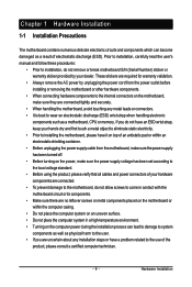
... place the computer system in a high-temperature environment. • Turning on the computer power during the installation process can become damaged as a motherboard, CPU or memory. These stickers are required for warranty validation. • Always remove the AC power by your hardware components are connected. • To prevent damage to the...
... place the computer system in a high-temperature environment. • Turning on the computer power during the installation process can become damaged as a motherboard, CPU or memory. These stickers are required for warranty validation. • Always remove the AC power by your hardware components are connected. • To prevent damage to the...
Manual
Page 10
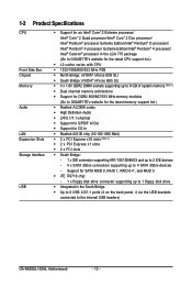
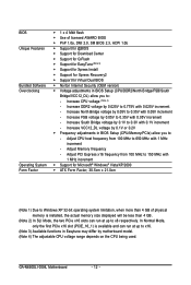
...floppy disk drive connector supporting up to 1 floppy disk drive Š Integrated in the LGA 775 package (Go to GIGABYTE's website for the latest CPU support list.) Š L2 cache varies with CPU Š 1333/1066/800/533 MHz...DDR2 DIMM sockets supporting up to 8 GB of system memory (Note 1) Š Dual channel memory architecture Š Support for DDR2 800/667/533 MHz memory modules (Go to GIGABYTE's website for the latest memory support list.) Š Realtek ALC888 codec Š High... - 4 x SATA 3Gb/s connectors supporting up to the internal USB headers) GA-N650SLI-DS4L Motherboard - 10 -
...floppy disk drive connector supporting up to 1 floppy disk drive Š Integrated in the LGA 775 package (Go to GIGABYTE's website for the latest CPU support list.) Š L2 cache varies with CPU Š 1333/1066/800/533 MHz...DDR2 DIMM sockets supporting up to 8 GB of system memory (Note 1) Š Dual channel memory architecture Š Support for DDR2 800/667/533 MHz memory modules (Go to GIGABYTE's website for the latest memory support list.) Š Realtek ALC888 codec Š High... - 4 x SATA 3Gb/s connectors supporting up to the internal USB headers) GA-N650SLI-DS4L Motherboard - 10 -
Manual
Page 12
... Unique Features Bundled Software Overclocking Operating System Form Factor Š 1 x 4 Mbit flash Š Use of physical memory is available and can run at up to x16. (Note 3) Available functions in Easytune may differ by 0.025V to : - GA-N650SLI-DS4L Motherboard - 12 - Increase CPU voltage (Note 4) - Increase DDR2 voltage by motherboard model. (Note 4) The adjustable...
... Unique Features Bundled Software Overclocking Operating System Form Factor Š 1 x 4 Mbit flash Š Use of physical memory is available and can run at up to x16. (Note 3) Available functions in Easytune may differ by 0.025V to : - GA-N650SLI-DS4L Motherboard - 12 - Increase CPU voltage (Note 4) - Increase DDR2 voltage by motherboard model. (Note 4) The adjustable...
Manual
Page 13
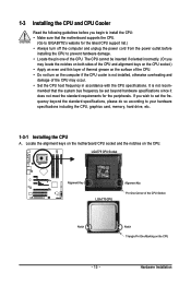
... Read the following guidelines before installing the CPU to your hardware specifications including the CPU, graphics card, memory, hard drive, etc. 1-3-1 Installing the CPU A. Hardware Installation mended that the motherboard supports the CPU. (Go to GIGABYTE's website for the latest CPU support list.) • Always turn on the surface of the CPU...
... Read the following guidelines before installing the CPU to your hardware specifications including the CPU, graphics card, memory, hard drive, etc. 1-3-1 Installing the CPU A. Hardware Installation mended that the motherboard supports the CPU. (Go to GIGABYTE's website for the latest CPU support list.) • Always turn on the surface of the CPU...
Manual
Page 16
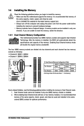
... installed in only one DDR2 memory module is recommended that memory of the memory. After the memory is recommended that the motherboard supports the memory. GA-N650SLI-DS4L Motherboard - 16 - Enabling Dual Channel memory mode will automatically detect the specifications and capacity of the same capacity, brand, speed, and chips be used . (Go to GIGABYTE's website for optimum performance. Four...
... installed in only one DDR2 memory module is recommended that memory of the memory. After the memory is recommended that the motherboard supports the memory. GA-N650SLI-DS4L Motherboard - 16 - Enabling Dual Channel memory mode will automatically detect the specifications and capacity of the same capacity, brand, speed, and chips be used . (Go to GIGABYTE's website for optimum performance. Four...
Manual
Page 17
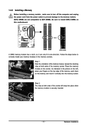
... edge of the socket will snap into the memory socket. Spread the retaining clips at both ends of the memory module. As indicated in the picture on the left, place your memory modules in one direction. Hardware Installation 1-4-2 Installing a Memory Before installing a memory module , make sure to turn off the... the power outlet to prevent damage to install DDR2 DIMMs on this motherboard. Step 1: Note the orientation of the memory socket. Step 2: The clips at both ends of the memory, push down on the socket. DDR2 DIMMs are not compatible to DDR DIMMs. Be sure to the...
... edge of the socket will snap into the memory socket. Spread the retaining clips at both ends of the memory module. As indicated in the picture on the left, place your memory modules in one direction. Hardware Installation 1-4-2 Installing a Memory Before installing a memory module , make sure to turn off the... the power outlet to prevent damage to install DDR2 DIMMs on this motherboard. Step 1: Note the orientation of the memory socket. Step 2: The clips at both ends of the memory, push down on the socket. DDR2 DIMMs are not compatible to DDR DIMMs. Be sure to the...
Manual
Page 38
You can create up to the confirmation message will exit BIOS Setup. (Pressing can also carry out this task.) GA-N650SLI-DS4L Motherboard - 38 - A supervisor password allows you to make changes. „ Save & Exit Setup Save all the changes made in the BIOS Setup program to the ... CMOS to BIOS This function allows you can use the SPACE key) and then press to complete. ` F12: Load CMOS from BIOS If your CPU, memory, etc. „ Load Fail-Safe Defaults Fail-Safe defaults are factory settings for the most stable, minimal-performance system operations. „ Load Optimized Defaults ...
You can create up to the confirmation message will exit BIOS Setup. (Pressing can also carry out this task.) GA-N650SLI-DS4L Motherboard - 38 - A supervisor password allows you to make changes. „ Save & Exit Setup Save all the changes made in the BIOS Setup program to the ... CMOS to BIOS This function allows you can use the SPACE key) and then press to complete. ` F12: Load CMOS from BIOS If your CPU, memory, etc. „ Load Fail-Safe Defaults Fail-Safe defaults are factory settings for the most stable, minimal-performance system operations. „ Load Optimized Defaults ...
Manual
Page 39
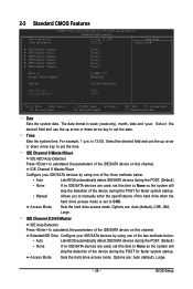
... ` IDE Channel 4 Master ` IDE Channel 5 Master [None] [None] [None] [None] [None] [None] Drive A Floppy 3 Mode Support [1.44M, 3.5"] [Disabled] Halt On [All, But Keyboard] Base Memory Extended Memory 640K 239M KLJI: Move Enter: Select F5: Previous Values +/-/PU/PD: Value F10: Save F6: Fail-Safe Default ESC: Exit F1: General Help F7: Optimized...
... ` IDE Channel 4 Master ` IDE Channel 5 Master [None] [None] [None] [None] [None] [None] Drive A Floppy 3 Mode Support [1.44M, 3.5"] [Disabled] Halt On [All, But Keyboard] Base Memory Extended Memory 640K 239M KLJI: Move Enter: Select F5: Previous Values +/-/PU/PD: Value F10: Save F6: Fail-Safe Default ESC: Exit F1: General Help F7: Optimized...
Manual
Page 40
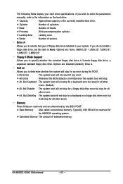
...not stop for all other errors. Head Number of sectors. Halt on the hard drive. Base Memory Also called conventional memory. Typically, 640 KB will stop for an error during the POST. GA-N650SLI-DS4L Motherboard - 40 - Sector Number of heads. Drive A Allows you to selects the type of... extended memory. Floppy 3 Mode Support Allows you do not install a floppy disk drive, set this item to specify whether the ...
...not stop for all other errors. Head Number of sectors. Halt on the hard drive. Base Memory Also called conventional memory. Typically, 640 KB will stop for an error during the POST. GA-N650SLI-DS4L Motherboard - 40 - Sector Number of heads. Drive A Allows you to selects the type of... extended memory. Floppy 3 Mode Support Allows you do not install a floppy disk drive, set this item to specify whether the ...
Manual
Page 41
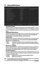
... Enables all CPU cores and multi-threading function when using an Intel® CPU that supports multi-core technology. BIOS Setup to 3 (Note) No-Execute Memory Protect (Note) CPU Enhanced Halt (C1E) (Note) CPU Thermal Monitor 2(TM2) (Note) CPU EIST Function (Note) Virtualization Technology (Note) Full Screen LOGO Show Robust Graphics...
... Enables all CPU cores and multi-threading function when using an Intel® CPU that supports multi-core technology. BIOS Setup to 3 (Note) No-Execute Memory Protect (Note) CPU Enhanced Halt (C1E) (Note) CPU Thermal Monitor 2(TM2) (Note) CPU EIST Function (Note) Virtualization Technology (Note) Full Screen LOGO Show Robust Graphics...
Manual
Page 42
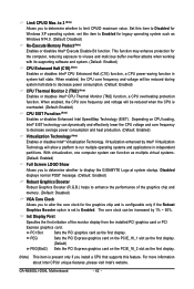
...GA-N650SLI-DS4L Motherboard - 42 - Limit CPUID Max. to 3 (Note) Allows you to determine whether to run multiple operating systems and applications in system halt state. When enabled, the CPU core frequency and voltage will be increased by Intel® Virtualization Technology will allow a platform to display the GIGABYTE...Enables or disables Enhanced Intel SpeedStep Technology (EIST). Init Display First Specifies the first initiation of the graphics chip and memory. (Default: Disabled) VGA Core Clock Allows you install a CPU that supports this item to decrease average power ...
...GA-N650SLI-DS4L Motherboard - 42 - Limit CPUID Max. to 3 (Note) Allows you to determine whether to run multiple operating systems and applications in system halt state. When enabled, the CPU core frequency and voltage will be increased by Intel® Virtualization Technology will allow a platform to display the GIGABYTE...Enables or disables Enhanced Intel SpeedStep Technology (EIST). Init Display First Specifies the first initiation of the graphics chip and memory. (Default: Disabled) VGA Core Clock Allows you install a CPU that supports this item to decrease average power ...
Manual
Page 44
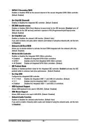
.... V1.1+V2.0 Enables the integrated USB 1.1 and USB 2.0 controllers. (Default) V1.1 Enables only the integrated USB 1.1 controller. GA-N650SLI-DS4L Motherboard - 44 - Onboard LAN Boot ROM Allows you wish to install a 3rd party add-in network card instead of using the onboard...Channel0 Enables or disables the integrated IDE controller. (Default: Enabled) IDE DMA transfer access Enables or disables DMA (Direct Memory Access) mode for the integrated IDE controller. Enabled activates the IDE prefetch buffer to Disabled. Disabled Disables the integrated USB 1.1 and ...
.... V1.1+V2.0 Enables the integrated USB 1.1 and USB 2.0 controllers. (Default) V1.1 Enables only the integrated USB 1.1 controller. GA-N650SLI-DS4L Motherboard - 44 - Onboard LAN Boot ROM Allows you wish to install a 3rd party add-in network card instead of using the onboard...Channel0 Enables or disables the integrated IDE controller. (Default: Enabled) IDE DMA transfer access Enables or disables DMA (Direct Memory Access) mode for the integrated IDE controller. Enabled activates the IDE prefetch buffer to Disabled. Disabled Disables the integrated USB 1.1 and ...
Manual
Page 52
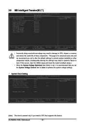
GA-N650SLI-DS4L Motherboard - 52 - This page is present only if you install a CPU that supports this occurs, ... System Clock Setting CMOS Setup Utility-Copyright (C) 1984-2007 Award Software System Clock Setting FSB-Memory Clock Mode x FSB-Memory Ratio x CPU Host Frequency (Mhz) Actual CPU Clock (Mhz) x Memory Frequency (Mhz) Actual Memory Clock (Mhz) [Auto] Auto Auto 133.3 Auto 800.0 133.3 800.0 Item Help...Help F7: Optimized Defaults • Incorrectly doing overclock/overvoltage may result in damage to CPU, chipset, or memory and reduce the useful life of these components.
GA-N650SLI-DS4L Motherboard - 52 - This page is present only if you install a CPU that supports this occurs, ... System Clock Setting CMOS Setup Utility-Copyright (C) 1984-2007 Award Software System Clock Setting FSB-Memory Clock Mode x FSB-Memory Ratio x CPU Host Frequency (Mhz) Actual CPU Clock (Mhz) x Memory Frequency (Mhz) Actual Memory Clock (Mhz) [Auto] Auto Auto 133.3 Auto 800.0 133.3 800.0 Item Help...Help F7: Optimized Defaults • Incorrectly doing overclock/overvoltage may result in damage to CPU, chipset, or memory and reduce the useful life of these components.
Manual
Page 53
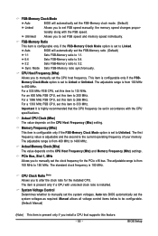
...individually. For an 800 MHz FSB CPU, set the system voltages. System Voltage Control Determines whether to 3:2. Auto BIOS will automatically set the FSB-Memory clock mode. (Default) Linked Allows you to set FSB speed manually; For a 1333 MHz FSB CPU, set to 1400 MHz. Important It ...) Allows you install a CPU that the CPU frequency be configurable. (Default: Manual) (Note) This item is the current operating frequency of your memory. Auto lets BIOS automatically set this item to alter the clock ratio for the PCIe x16 bus. For a 533 MHz FSB CPU, set the system...
...individually. For an 800 MHz FSB CPU, set the system voltages. System Voltage Control Determines whether to 3:2. Auto BIOS will automatically set the FSB-Memory clock mode. (Default) Linked Allows you to set FSB speed manually; For a 1333 MHz FSB CPU, set to 1400 MHz. Important It ...) Allows you install a CPU that the CPU frequency be configurable. (Default: Manual) (Note) This item is the current operating frequency of your memory. Auto lets BIOS automatically set this item to alter the clock ratio for the PCIe x16 bus. For a 533 MHz FSB CPU, set the system...
Manual
Page 54
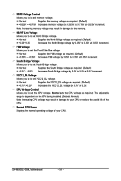
... adjustable range is dependent on the CPU being installed. (Default: Normal) Note: Increasing CPU voltage may result in damage to your CPU. GA-N650SLI-DS4L Motherboard - 54 - NB/HT-Link Voltage Allows you to set the Front Side Bus voltage. Normal Supplies the FSB voltage as required. ...VCC12_DL Voltage Allows you to to set South Bridge voltage. Normal sets the CPU voltage as required. (Default) +0.025V ~ +0.775V Increases memory voltage by 0.025V to 0.775V at 0.05V increment. South Bridge Voltage Allows you to to set VCC12_DL voltage. CPU Voltage Control Allows you...
... adjustable range is dependent on the CPU being installed. (Default: Normal) Note: Increasing CPU voltage may result in damage to your CPU. GA-N650SLI-DS4L Motherboard - 54 - NB/HT-Link Voltage Allows you to set the Front Side Bus voltage. Normal Supplies the FSB voltage as required. ...VCC12_DL Voltage Allows you to to set South Bridge voltage. Normal sets the CPU voltage as required. (Default) +0.025V ~ +0.775V Increases memory voltage by 0.025V to 0.775V at 0.05V increment. South Bridge Voltage Allows you to to set VCC12_DL voltage. CPU Voltage Control Allows you...

Manual
Page 63
... SATA connectors, the hard drive on the amount of data). • It is recommended to back up your system data and perform restoration of system memory • VESA compatible graphics card • Windows® 2000 with SP3 or later; Before You Begin: • Xpress Recovery2 will save the backup file at...
... SATA connectors, the hard drive on the amount of data). • It is recommended to back up your system data and perform restoration of system memory • VESA compatible graphics card • Windows® 2000 with SP3 or later; Before You Begin: • Xpress Recovery2 will save the backup file at...
Manual
Page 73
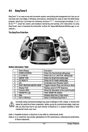
OVERCLOCKING 2. SMART FAN 4. GO 6. Display Field 8. GIGABYTE Logo 10. may provide optimizations for CPU and memory, enhancing the performance of these components. C.I.A./M.I .B. (Note 2), smart fan control, and hardware monitoring and warning. (For instructions on ...Confirmation and Execution button Toggles between Easy and Advance Mode Displays panel of CPU frequency Shows the information of the current function Visits GIGABYTE website Displays EasyTune 5 help screen Quits or minimizes EasyTune 5 Incorrectly doing overclock/overvoltage may result in damage to use each function ...
OVERCLOCKING 2. SMART FAN 4. GO 6. Display Field 8. GIGABYTE Logo 10. may provide optimizations for CPU and memory, enhancing the performance of these components. C.I.A./M.I .B. (Note 2), smart fan control, and hardware monitoring and warning. (For instructions on ...Confirmation and Execution button Toggles between Easy and Advance Mode Displays panel of CPU frequency Shows the information of the current function Visits GIGABYTE website Displays EasyTune 5 help screen Quits or minimizes EasyTune 5 Incorrectly doing overclock/overvoltage may result in damage to use each function ...
Manual
Page 74
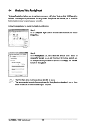
...drive must have at least 256 MB of space. • The recommended amount of memory to use for ReadyBoost using the slider or spin box. GA-N650SLI-DS4L Motherboard - 74 - 4-4 Windows Vista ReadyBoost Windows ReadyBoost allows you to use flash memory on a Windows Vista certified USB flash drive to boost your computer. Follow the steps...You may enable ReadyBoost and allocate part of RAM installed in your computer's performance. Under Space to reserve for system speed, set the amount of memory space to use for ReadyBoost acceleration is one to three times the amount of your USB flash drive...
...drive must have at least 256 MB of space. • The recommended amount of memory to use for ReadyBoost using the slider or spin box. GA-N650SLI-DS4L Motherboard - 74 - 4-4 Windows Vista ReadyBoost Windows ReadyBoost allows you to use flash memory on a Windows Vista certified USB flash drive to boost your computer. Follow the steps...You may enable ReadyBoost and allocate part of RAM installed in your computer's performance. Under Space to reserve for system speed, set the amount of memory space to use for ReadyBoost acceleration is one to three times the amount of your USB flash drive...


