
Manual
Page 1
GA-MA790XT-UD4P AM3 socket motherboard for AMD PhenomTM II X4 processor/AMD PhenomTM II X3 processor User's Manual Rev. 1004 12ME-MA79T4P-1004R
GA-MA790XT-UD4P AM3 socket motherboard for AMD PhenomTM II X4 processor/AMD PhenomTM II X3 processor User's Manual Rev. 1004 12ME-MA79T4P-1004R
Manual
Page 3
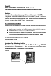
... Guide page on our website. For product-related information, check on our website at: http://www.gigabyte.com.tw Identifying Your Motherboard Revision The revision number on how to assist in this manual may be reproduced, copied, translated, transmitted, or published in ... and features in any form or by copyright laws and is 1.0. All rights reserved. Check your motherboard looks like this product, GIGABYTE provides the following types of documentations: For quick set-up of GIGABYTE. Copyright © 2009 GIGA-BYTE TECHNOLOGY CO., LTD. For example, "REV: 1.0" means the...
... Guide page on our website. For product-related information, check on our website at: http://www.gigabyte.com.tw Identifying Your Motherboard Revision The revision number on how to assist in this manual may be reproduced, copied, translated, transmitted, or published in ... and features in any form or by copyright laws and is 1.0. All rights reserved. Check your motherboard looks like this product, GIGABYTE provides the following types of documentations: For quick set-up of GIGABYTE. Copyright © 2009 GIGA-BYTE TECHNOLOGY CO., LTD. For example, "REV: 1.0" means the...
Manual
Page 4
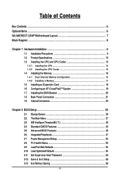
Table of Contents Box Contents ...6 OptionalItems ...6 GA-MA790XT-UD4P Motherboard Layout 7 Block Diagram ...8 Chapter 1 Hardware Installation 9 1-1 Installation Precautions 9 1-2 Product Specifications 10 1-3 Installing the CPU and CPU Cooler 13 1-3-1 Installing the CPU 13 1-3-2 Installing the CPU ...
Table of Contents Box Contents ...6 OptionalItems ...6 GA-MA790XT-UD4P Motherboard Layout 7 Block Diagram ...8 Chapter 1 Hardware Installation 9 1-1 Installation Precautions 9 1-2 Product Specifications 10 1-3 Installing the CPU and CPU Cooler 13 1-3-1 Installing the CPU 13 1-3-2 Installing the CPU ...
Manual
Page 6
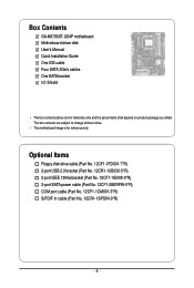
Box Contents GA-MA790XT-UD4P motherboard Motherboard driver disk User's Manual Quick Installation Guide One IDE cable Four SATA 3Gb/s cables One SATA bracket I/O Shield • The box contents above are subject to change without notice. • The motherboard image is for reference only and the actual items shall depend on product package you obtain. Optional Items...
Box Contents GA-MA790XT-UD4P motherboard Motherboard driver disk User's Manual Quick Installation Guide One IDE cable Four SATA 3Gb/s cables One SATA bracket I/O Shield • The box contents above are subject to change without notice. • The motherboard image is for reference only and the actual items shall depend on product package you obtain. Optional Items...

Manual
Page 7
GA-MA790XT-UD4P Motherboard Layout KB_MS CPU_FAN ATX RCA_SPDIF ATX_12V_2X4 R_USB Socket AM3 USB_1394_1 USB_1394 PWR_FAN USB IT8720 LAN AUDIO F_AUDIO PCIEX1_1 RTL8111C/D(L) PCIEX16_1 PCIEX1_2 CD_IN CODEC PCIEX1_3 SPDIF_IN SPDIF_OUT PCIEX8_1 PCI1 PCI2 COM FDD CI IDE AMD 790X DDR3_1 DDR3_2 DDR3_3 DDR3_4 GA-MA790XT-UD4P CLR_CMOS BATTERY AMD SB750 B_BIOS M_BIOS SATA2_4 SATA2_5 SATA2_2 SATA2_3 SATA2_0 SATA2_1 TSB43AB23 GIGABYTE SATA2 GSATA2_0 GSATA2_1 PWR_LED F_USB1 F_PANEL F_1394 F_USB2 SYS_FAN2 SYS_FAN1 - 7 -
GA-MA790XT-UD4P Motherboard Layout KB_MS CPU_FAN ATX RCA_SPDIF ATX_12V_2X4 R_USB Socket AM3 USB_1394_1 USB_1394 PWR_FAN USB IT8720 LAN AUDIO F_AUDIO PCIEX1_1 RTL8111C/D(L) PCIEX16_1 PCIEX1_2 CD_IN CODEC PCIEX1_3 SPDIF_IN SPDIF_OUT PCIEX8_1 PCI1 PCI2 COM FDD CI IDE AMD 790X DDR3_1 DDR3_2 DDR3_3 DDR3_4 GA-MA790XT-UD4P CLR_CMOS BATTERY AMD SB750 B_BIOS M_BIOS SATA2_4 SATA2_5 SATA2_2 SATA2_3 SATA2_0 SATA2_1 TSB43AB23 GIGABYTE SATA2 GSATA2_0 GSATA2_1 PWR_LED F_USB1 F_PANEL F_1394 F_USB2 SYS_FAN2 SYS_FAN1 - 7 -

Manual
Page 9
... all cables and power connectors of your hardware components are connected. • To prevent damage to the motherboard, do not allow screws to come in contact with the motherboard circuit or its components. • Make sure there are no leftover screws or metal components placed on ... in a high-temperature environment. • Turning on the power, make sure they are connected tightly and securely. • When handling the motherboard, avoid touching any metal leads or connectors. • It is best to wear an electrostatic discharge (ESD) wrist strap when handling electronic components...
... all cables and power connectors of your hardware components are connected. • To prevent damage to the motherboard, do not allow screws to come in contact with the motherboard circuit or its components. • Make sure there are no leftover screws or metal components placed on ... in a high-temperature environment. • Turning on the power, make sure they are connected tightly and securely. • When handling the motherboard, avoid touching any metal leads or connectors. • It is best to wear an electrostatic discharge (ESD) wrist strap when handling electronic components...
Manual
Page 10
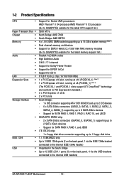
... Audio 2/4/5.1/7.1-channel Support for Dolby® Home Theater Support for S/PDIF In/Out Support for SATA RAID 0, RAID 1, RAID 5, RAID 10, and JBOD GIGABYTE SATA2 chip: - 2 x SATA 3Gb/s connectors (GSATA2_0, GSATA2_1) supporting up to 2 SATA 3Gb/s devices - Support for CD In RTL8111C/D(L) chip (10... Support for SATA RAID 0, RAID 1, and JBOD iTE IT8720 chip: - 1 x floppy disk drive connector supporting up to the internal USB headers) GA-MA790XT-UD4P Motherboard - 10 - TSB43AB23 chip Up to 3 IEEE 1394a ports (2 on the back panel, 1 via the IEEE 1394a bracket connected to the internal IEEE...
... Audio 2/4/5.1/7.1-channel Support for Dolby® Home Theater Support for S/PDIF In/Out Support for SATA RAID 0, RAID 1, RAID 5, RAID 10, and JBOD GIGABYTE SATA2 chip: - 2 x SATA 3Gb/s connectors (GSATA2_0, GSATA2_1) supporting up to 2 SATA 3Gb/s devices - Support for CD In RTL8111C/D(L) chip (10... Support for SATA RAID 0, RAID 1, and JBOD iTE IT8720 chip: - 1 x floppy disk drive connector supporting up to the internal USB headers) GA-MA790XT-UD4P Motherboard - 10 - TSB43AB23 chip Up to 3 IEEE 1394a ports (2 on the back panel, 1 via the IEEE 1394a bracket connected to the internal IEEE...

Manual
Page 12
... you install. (Note 4) Available functions in the PCIEX16_1 slot. When PCIEX8_1 is supported will operate at up to install it in EasyTune may differ by motherboard model. GA-MA790XT-UD4P Motherboard - 12 - Unique Features Bundled Software Operating System Form Factor Support for @BIOS Support for Q-Flash Support for Xpress BIOS Rescue ...
... you install. (Note 4) Available functions in the PCIEX16_1 slot. When PCIEX8_1 is supported will operate at up to install it in EasyTune may differ by motherboard model. GA-MA790XT-UD4P Motherboard - 12 - Unique Features Bundled Software Operating System Form Factor Support for @BIOS Support for Q-Flash Support for Xpress BIOS Rescue ...
Manual
Page 13
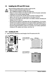
... including the CPU, graphics card, memory, hard drive, etc. 1-3-1 Installing the CPU A. Locate the pin one of the CPU. mended that the motherboard supports the CPU. (Go to GIGABYTE's website for the peripherals. A Small Triangle Mark Denotes Pin One of the Socket AM3 Socket A Small Triangle Marking Denotes CPU Pin One AM3...
... including the CPU, graphics card, memory, hard drive, etc. 1-3-1 Installing the CPU A. Locate the pin one of the CPU. mended that the motherboard supports the CPU. (Go to GIGABYTE's website for the peripherals. A Small Triangle Mark Denotes Pin One of the Socket AM3 Socket A Small Triangle Marking Denotes CPU Pin One AM3...

Manual
Page 14
... (small triangle marking) with the triangle mark on the middle of the CPU, lowering the locking lever and latching it into the fully locked position. GA-MA790XT-UD4P Motherboard - 14 - CPU Socket Locking Lever Step 1: Completely lift up the CPU socket locking lever. The CPU cannot fit in if oriented incorrectly. Adjust the ...CPU orientation if this occurs. Do not force the CPU into the motherboard CPU socket. Follow the steps below to the CPU. Make sure that the CPU pins fit perfectly into the socket.
... (small triangle marking) with the triangle mark on the middle of the CPU, lowering the locking lever and latching it into the fully locked position. GA-MA790XT-UD4P Motherboard - 14 - CPU Socket Locking Lever Step 1: Completely lift up the CPU socket locking lever. The CPU cannot fit in if oriented incorrectly. Adjust the ...CPU orientation if this occurs. Do not force the CPU into the motherboard CPU socket. Follow the steps below to the CPU. Make sure that the CPU pins fit perfectly into the socket.

Manual
Page 15
... - 15 - 1-3-2 Installing the CPU Cooler Follow the steps below to correctly install the CPU cooler on the CPU. (The following procedure uses the GIGABYTE cooler as the picture above shows) to lock into place. (Refer to your CPU cooler installation manual for instructions on installing the cooler.) Step 5: ...Finally, attach the power connector of the CPU cooler to the CPU fan header (CPU_FAN) on the motherboard. Step 2: Place the CPU cooler on one side of the retention frame. Step 3: Hook the CPU cooler clip to the mounting lug on the...
... - 15 - 1-3-2 Installing the CPU Cooler Follow the steps below to correctly install the CPU cooler on the CPU. (The following procedure uses the GIGABYTE cooler as the picture above shows) to lock into place. (Refer to your CPU cooler installation manual for instructions on installing the cooler.) Step 5: ...Finally, attach the power connector of the CPU cooler to the CPU fan header (CPU_FAN) on the motherboard. Step 2: Place the CPU cooler on one side of the retention frame. Step 3: Hook the CPU cooler clip to the mounting lug on the...
Manual
Page 16
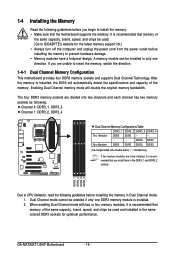
...the power outlet before installing the memory to insert the memory, switch the direction. 1-4-1 Dual Channel Memory Configuration This motherboard provides four DDR3 memory sockets and supports Dual Channel Technology. A memory module can be enabled if only one direction....recommended that the motherboard supports the memory. GA-MA790XT-UD4P Motherboard - 16 - After the memory is installed, the BIOS will double the original memory bandwidth. DDR3_1 DDR3_2 DDR3_3 DDR3_4 Due to CPU limitation, read the following guidelines before you are to GIGABYTE's website for optimum...
...the power outlet before installing the memory to insert the memory, switch the direction. 1-4-1 Dual Channel Memory Configuration This motherboard provides four DDR3 memory sockets and supports Dual Channel Technology. A memory module can be enabled if only one direction....recommended that the motherboard supports the memory. GA-MA790XT-UD4P Motherboard - 16 - After the memory is installed, the BIOS will double the original memory bandwidth. DDR3_1 DDR3_2 DDR3_3 DDR3_4 Due to CPU limitation, read the following guidelines before you are to GIGABYTE's website for optimum...

Manual
Page 17
... DIMM A DDR3 memory module has a notch, so it vertically into place when the memory module is securely inserted. - 17 - Place the memory module on this motherboard. 1-4-2 Installing a Memory Before installing a memory module , make sure to turn off the computer and unplug the power cord from the power outlet to prevent damage...
... DIMM A DDR3 memory module has a notch, so it vertically into place when the memory module is securely inserted. - 17 - Place the memory module on this motherboard. 1-4-2 Installing a Memory Before installing a memory module , make sure to turn off the computer and unplug the power cord from the power outlet to prevent damage...
Manual
Page 18
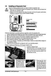
... inserted into the slot. 4. Locate an expansion slot that came with the expansion card in the slot. 3. Install the driver provided with your operating system. GA-MA790XT-UD4P Motherboard - 18 - • Removing the Card from the PCIEX8_1 slot: Press the white latch at the end of the card until it is securely seated in... panel. 2. After installing all expansion cards, replace the chassis cover(s). 6. If necessary, go to BIOS Setup to install an expansion card: • Make sure the motherboard supports the expansion card. Remove the metal slot cover from the slot.
... inserted into the slot. 4. Locate an expansion slot that came with the expansion card in the slot. 3. Install the driver provided with your operating system. GA-MA790XT-UD4P Motherboard - 18 - • Removing the Card from the PCIEX8_1 slot: Press the white latch at the end of the card until it is securely seated in... panel. 2. After installing all expansion cards, replace the chassis cover(s). 6. If necessary, go to BIOS Setup to install an expansion card: • Make sure the motherboard supports the expansion card. Remove the metal slot cover from the slot.
Manual
Page 19
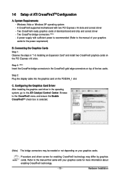
... screen for enabling CrossFireX technology may be needed or not depending on top of your graphics cards for the power requirement) B. Hardware Installation A CrossFireX-supported motherboard with your graphics cards for more information about enabling CrossFireX technology. - 19 - Connecting the Graphics Cards Step 1: Observe the steps in "1-5 Installing an Expansion Card...
... screen for enabling CrossFireX technology may be needed or not depending on top of your graphics cards for the power requirement) B. Hardware Installation A CrossFireX-supported motherboard with your graphics cards for more information about enabling CrossFireX technology. - 19 - Connecting the Graphics Cards Step 1: Observe the steps in "1-5 Installing an Expansion Card...

Manual
Page 20
...connector on your system and the power switch on the bracket. Before connecting the SATA signal cable, make sure to turn off your motherboard. For SATA device in external enclosure, you to connect external SATA device(s) to your SATA device. Step 2: Connect the SATA ...bracket, one SATA signal cable, and one end of the external enclosure. Step 3: Step 4: Connect the power Plug one SATA power cable. GA-MA790XT-UD4P Motherboard - 20 - 1-7 Installing the SATA Bracket The SATA bracket allows you only need to connect the SATA signal cable. Follow the steps below...
...connector on your system and the power switch on the bracket. Before connecting the SATA signal cable, make sure to turn off your motherboard. For SATA device in external enclosure, you to connect external SATA device(s) to your SATA device. Step 2: Connect the SATA ...bracket, one SATA signal cable, and one end of the external enclosure. Step 3: Step 4: Connect the power Plug one SATA power cable. GA-MA790XT-UD4P Motherboard - 20 - 1-7 Installing the SATA Bracket The SATA bracket allows you only need to connect the SATA signal cable. Follow the steps below...

Manual
Page 21
... drive and etc. USB Port The USB port supports the USB 2.0/1.1 specification. Use this feature, ensure that your device and then remove it from the motherboard. • When removing the cable, pull it side to side to a back panel connector, first remove the cable from your audio system provides a coaxial digital...
... drive and etc. USB Port The USB port supports the USB 2.0/1.1 specification. Use this feature, ensure that your device and then remove it from the motherboard. • When removing the cable, pull it side to side to a back panel connector, first remove the cable from your audio system provides a coaxial digital...

Manual
Page 22
... connect side speakers in a 4/5.1/7.1-channel audio configuration. Line Out Jack (Green) The default line out jack. Line In Jack (Blue) The default line in jack. GA-MA790XT-UD4P Motherboard - 22 - This jack can be connected to this audio jack to connect front speakers in a 4/5.1/7.1-channel audio configuration. Refer to perform different functions via the...
... connect side speakers in a 4/5.1/7.1-channel audio configuration. Line Out Jack (Green) The default line out jack. Line In Jack (Blue) The default line in jack. GA-MA790XT-UD4P Motherboard - 22 - This jack can be connected to this audio jack to connect front speakers in a 4/5.1/7.1-channel audio configuration. Refer to perform different functions via the...

Manual
Page 23
..., make sure your devices are compliant with the connectors you wish to connect. • Before installing the devices, be sure to the connector on the motherboard. - 23 -
..., make sure your devices are compliant with the connectors you wish to connect. • Before installing the devices, be sure to the connector on the motherboard. - 23 -

Manual
Page 24
... providing a 2x4 12V and a 2x12 power connector, remove the protective covers from the 12V power connector and the main power connector on the motherboard. If the 12V power connector is not connected, the computer will not start. • To meet expansion requirements, it is recommended that a... 3.3V -12V GND PS_ON(soft On/Off) GND GND GND -5V +5V +5V +5V (Only for 2x12-pin ATX) GND (Only for 2x12-pin ATX) GA-MA790XT-UD4P Motherboard - 24 - When using a power supply providing a 2x2 12V and a 2x10 power connector. 8 4 5 1 ATX_12V_2X4 ATX_12V_2X4: Pin No. 1/2) ATX_12V_2X4/ATX (2x4...
... providing a 2x4 12V and a 2x12 power connector, remove the protective covers from the 12V power connector and the main power connector on the motherboard. If the 12V power connector is not connected, the computer will not start. • To meet expansion requirements, it is recommended that a... 3.3V -12V GND PS_ON(soft On/Off) GND GND GND -5V +5V +5V +5V (Only for 2x12-pin ATX) GND (Only for 2x12-pin ATX) GA-MA790XT-UD4P Motherboard - 24 - When using a power supply providing a 2x2 12V and a 2x10 power connector. 8 4 5 1 ATX_12V_2X4 ATX_12V_2X4: Pin No. 1/2) ATX_12V_2X4/ATX (2x4...


