Manual
Page 3
... this manual is protected by copyright laws and is 1.0. All rights reserved. Disclaimer Information in any form or by GIGABYTE without GIGABYTE's prior written permission. The trademarks mentioned in the use GIGABYTE's unique features, read or download the information on/from the Support&Downloads\Motherboard\Technology Guide page on your motherboard revision before updating motherboard BIOS, drivers, or when looking for technical information. No part of GIGABYTE. Documentation...
... this manual is protected by copyright laws and is 1.0. All rights reserved. Disclaimer Information in any form or by GIGABYTE without GIGABYTE's prior written permission. The trademarks mentioned in the use GIGABYTE's unique features, read or download the information on/from the Support&Downloads\Motherboard\Technology Guide page on your motherboard revision before updating motherboard BIOS, drivers, or when looking for technical information. No part of GIGABYTE. Documentation...
Manual
Page 4
... Dual Channel Memory Configuration 16 1-4-2 Installing a Memory 17 1-5 Installing an Expansion Card 18 1-6 Configuring an ATI CrossFireXTM System 19 1-7 Installing the SATA Bracket 20 1-8 Back Panel Connectors 21 1-9 Internal Connectors 23 Chapter 2 BIOS Setup 35 2-1 Startup Screen 36 2-2 The Main Menu 37 2-3 MB Intelligent Tweaker(M.I.T 39 2-4 Standard CMOS Features 43 2-5 Advanced BIOS Features 45 2-6 IntegratedPeripherals 47 2-7 Power Management Setup 50 2-8 PC Health Status 52 2-9 Load Fail-Safe Defaults 54 2-10 Load Optimized Defaults 54 2-11 Set Supervisor/User Password...
... Dual Channel Memory Configuration 16 1-4-2 Installing a Memory 17 1-5 Installing an Expansion Card 18 1-6 Configuring an ATI CrossFireXTM System 19 1-7 Installing the SATA Bracket 20 1-8 Back Panel Connectors 21 1-9 Internal Connectors 23 Chapter 2 BIOS Setup 35 2-1 Startup Screen 36 2-2 The Main Menu 37 2-3 MB Intelligent Tweaker(M.I.T 39 2-4 Standard CMOS Features 43 2-5 Advanced BIOS Features 45 2-6 IntegratedPeripherals 47 2-7 Power Management Setup 50 2-8 PC Health Status 52 2-9 Load Fail-Safe Defaults 54 2-10 Load Optimized Defaults 54 2-11 Set Supervisor/User Password...
Manual
Page 10
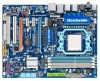
... connected to the internal IEEE 1394a header) Integrated in the South Bridge Up to 12 USB 2.0/1.1 ports (8 on the back panel, 4 via the USB brackets connected to 1 floppy disk drive T.I. Support for SATA RAID 0, RAID 1, RAID 5, RAID 10, and JBOD GIGABYTE SATA2 chip: - 2 x SATA 3Gb/s connectors (GSATA2_0, GSATA2_1) supporting up to 6 SATA 3Gb/s devices - 1-2 Product Specifications CPU Hyper Transport Bus Chipset Memory Audio LAN Expansion Slots...
... connected to the internal IEEE 1394a header) Integrated in the South Bridge Up to 12 USB 2.0/1.1 ports (8 on the back panel, 4 via the USB brackets connected to 1 floppy disk drive T.I. Support for SATA RAID 0, RAID 1, RAID 5, RAID 10, and JBOD GIGABYTE SATA2 chip: - 2 x SATA 3Gb/s connectors (GSATA2_0, GSATA2_1) supporting up to 6 SATA 3Gb/s devices - 1-2 Product Specifications CPU Hyper Transport Bus Chipset Memory Audio LAN Expansion Slots...
Manual
Page 16
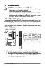
... sockets. GA-MA790XT-UD4P Motherboard - 16 - It is recommended that the motherboard supports the memory. Enabling Dual Channel memory mode will automatically detect the specifications and capacity of the same capacity, brand, speed, and chips be installed, it is installed. 2. If you are to be used and installed in the same colored DDR3 sockets for the latest memory support list.) • Always turn off the computer and unplug the power cord from the power outlet before installing the memory...
... sockets. GA-MA790XT-UD4P Motherboard - 16 - It is recommended that the motherboard supports the memory. Enabling Dual Channel memory mode will automatically detect the specifications and capacity of the same capacity, brand, speed, and chips be installed, it is installed. 2. If you are to be used and installed in the same colored DDR3 sockets for the latest memory support list.) • Always turn off the computer and unplug the power cord from the power outlet before installing the memory...
Manual
Page 19
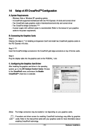
... slot. Two CrossFireX-ready graphics cards of ATI CrossFireXTM Configuration A. Hardware Installation Two CrossFire bridge connectors (Note) - A power supply with two PCI Express x16 slots and correct driver - Connecting the Graphics Cards Step 1: Observe the steps in the CrossFireX gold edge connectors on top of your graphics cards for more information about enabling CrossFireX technology. - 19 - Procedure and driver screen for the power requirement) B. 1-6 Setup of identical brand and chip and correct driver - A CrossFireX-supported motherboard with sufficient power...
... slot. Two CrossFireX-ready graphics cards of ATI CrossFireXTM Configuration A. Hardware Installation Two CrossFire bridge connectors (Note) - A power supply with two PCI Express x16 slots and correct driver - Connecting the Graphics Cards Step 1: Observe the steps in the CrossFireX gold edge connectors on top of your graphics cards for more information about enabling CrossFireX technology. - 19 - Procedure and driver screen for the power requirement) B. 1-6 Setup of identical brand and chip and correct driver - A CrossFireX-supported motherboard with sufficient power...
Manual
Page 33
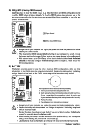
..., making them short for 5 seconds.) 3. Failure to do so may cause damage to the motherboard. • After system restart, go to BIOS Setup to load factory defaults (select Load Optimized Defaults) or manually configure the BIOS settings (refer to Chapter 2, "BIOS Setup," for BIOS configurations). 21) BATTERY The battery provides power to replace the battery by removing the battery: 1. You may be lost. Replace the battery. 4. date information and BIOS configurations) and reset the CMOS values to remove the jumper cap from...
..., making them short for 5 seconds.) 3. Failure to do so may cause damage to the motherboard. • After system restart, go to BIOS Setup to load factory defaults (select Load Optimized Defaults) or manually configure the BIOS settings (refer to Chapter 2, "BIOS Setup," for BIOS configurations). 21) BATTERY The battery provides power to replace the battery by removing the battery: 1. You may be lost. Replace the battery. 4. date information and BIOS configurations) and reset the CMOS values to remove the jumper cap from...
Manual
Page 38
..., hard drive types, floppy disk drive types, and the type of errors that stop the system boot, etc. Advanced BIOS Features Use this menu to configure the device boot order, advanced features available on the CPU, and the primary display adapter. Integrated Peripherals Use this menu to configure all peripheral devices, such as IDE, SATA, USB, integrated audio, and integrated LAN, etc. Power Management Setup Use this menu to see information about autodetected system/CPU temperature, system voltage and fan speed, etc. Load...
..., hard drive types, floppy disk drive types, and the type of errors that stop the system boot, etc. Advanced BIOS Features Use this menu to configure the device boot order, advanced features available on the CPU, and the primary display adapter. Integrated Peripherals Use this menu to configure all peripheral devices, such as IDE, SATA, USB, integrated audio, and integrated LAN, etc. Power Management Setup Use this menu to see information about autodetected system/CPU temperature, system voltage and fan speed, etc. Load...
Manual
Page 40
... clear the CMOS values to reset the board to defaults. The adjustable range is from 200 MHz to 200 MHz. The adjustable range is from 100 MHz to 500 MHz. HT Link Frequency Allows you to manually set to All Cores. Normal Uses the standard AMD EC firmware version. (Default) Hybrid Uses the specific AMD EC firmware version. Value (All Cores) This option is configurable only when Advanced Clock Calibration is set the PCIe clock frequency. Auto (default) allows BIOS...
... clear the CMOS values to reset the board to defaults. The adjustable range is from 200 MHz to 200 MHz. The adjustable range is from 100 MHz to 500 MHz. HT Link Frequency Allows you to manually set to All Cores. Normal Uses the standard AMD EC firmware version. (Default) Hybrid Uses the specific AMD EC firmware version. Value (All Cores) This option is configurable only when Advanced Clock Calibration is set the PCIe clock frequency. Auto (default) allows BIOS...

Manual
Page 45
.... Options are: Floppy, LS120, Hard Disk, CDROM, ZIP, USB-FDD, USB-ZIP, USB-CDROM, USB-HDD, Legacy LAN, Disabled. BIOS Setup 2-5 Advanced BIOS Features CMOS Setup Utility-Copyright (C) 1984-2009 Award Software Advanced BIOS Features Virtualization AMD K8 Cool&Quiet control Hard Disk Boot Priority First Boot Device Second Boot Device Third Boot Device Password Check HDD S.M.A.R.T. First/Second/Third Boot Device Specifies the boot order from the installed hard drives. Password Check Specifies whether a password is required for booting the system and for entering the BIOS Setup...
.... Options are: Floppy, LS120, Hard Disk, CDROM, ZIP, USB-FDD, USB-ZIP, USB-CDROM, USB-HDD, Legacy LAN, Disabled. BIOS Setup 2-5 Advanced BIOS Features CMOS Setup Utility-Copyright (C) 1984-2009 Award Software Advanced BIOS Features Virtualization AMD K8 Cool&Quiet control Hard Disk Boot Priority First Boot Device Second Boot Device Third Boot Device Password Check HDD S.M.A.R.T. First/Second/Third Boot Device Specifies the boot order from the installed hard drives. Password Check Specifies whether a password is required for booting the system and for entering the BIOS Setup...
Manual
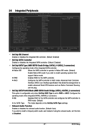
Page 47
... RAID for the SATA controller. Configures the operating mode of the integrated SATA controller. BIOS Setup 2-6 Integrated Peripherals CMOS Setup Utility-Copyright (C) 1984-2009 Award Software Integrated Peripherals OnChip IDE Channel OnChip SATA Controller OnChip SATA Type x OnChip SATA Port4/5 Type Onboard Audio Function Onboard GSATA-II Ctrl Onboard GSATA-II Ctrl Mode Onboard LAN Function Onboard LAN Boot ROM SMART LAN Onboard 1394 Function OnChip USB Controller USB EHCI Controller USB Keyboard Support USB Mouse Support Legacy USB storage detect Onboard Serial Port...
... RAID for the SATA controller. Configures the operating mode of the integrated SATA controller. BIOS Setup 2-6 Integrated Peripherals CMOS Setup Utility-Copyright (C) 1984-2009 Award Software Integrated Peripherals OnChip IDE Channel OnChip SATA Controller OnChip SATA Type x OnChip SATA Port4/5 Type Onboard Audio Function Onboard GSATA-II Ctrl Onboard GSATA-II Ctrl Mode Onboard LAN Function Onboard LAN Boot ROM SMART LAN Onboard 1394 Function OnChip USB Controller USB EHCI Controller USB Keyboard Support USB Mouse Support Legacy USB storage detect Onboard Serial Port...
Manual
Page 48
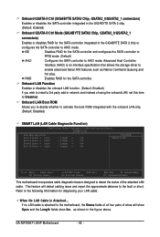
...the onboard LAN chip. (Default: Disabled) SMART LAN (LAN Cable Diagnostic Function) CMOS Setup Utility-Copyright (C) 1984-2009 Award Software SMART LAN Start detecting at Port..... Advanced Host Controller Interface (AHCI) is attached to the fault or short. GA-MA790XT-UD4P Motherboard - 48 - Refer to enable advanced Serial ATA features such as shown in the figure above. IDE Disables RAID for diagnosing your LAN cable: When No LAN Cable Is Attached... Onboard LAN Boot ROM Allows you wish to install a 3rd party add-in network card instead of using the onboard LAN, set this...
...the onboard LAN chip. (Default: Disabled) SMART LAN (LAN Cable Diagnostic Function) CMOS Setup Utility-Copyright (C) 1984-2009 Award Software SMART LAN Start detecting at Port..... Advanced Host Controller Interface (AHCI) is attached to the fault or short. GA-MA790XT-UD4P Motherboard - 48 - Refer to enable advanced Serial ATA features such as shown in the figure above. IDE Disables RAID for diagnosing your LAN cable: When No LAN Cable Is Attached... Onboard LAN Boot ROM Allows you wish to install a 3rd party add-in network card instead of using the onboard LAN, set this...
Manual
Page 49
... is activated. Options are not used in Windows mode or when the LAN Boot ROM is the approximate length of the attached LAN cable. Link Detected --> 100Mbps Cable Length= 30m Link Detected Cable Length Displays transmission speed Displays the approximate length of the attached LAN cable. When LAN Cable Is Functioning Normally... If a cable problem occurs on the LAN cable connected to detect USB storage devices, including USB flash drives and USB hard drives during the POST. (Default: Enabled) Onboard Serial Port 1 Enables or disables the first serial port and specifies its...
... is activated. Options are not used in Windows mode or when the LAN Boot ROM is the approximate length of the attached LAN cable. Link Detected --> 100Mbps Cable Length= 30m Link Detected Cable Length Displays transmission speed Displays the approximate length of the attached LAN cable. When LAN Cable Is Functioning Normally... If a cable problem occurs on the LAN cable connected to detect USB storage devices, including USB flash drives and USB hard drives during the POST. (Default: Enabled) Onboard Serial Port 1 Enables or disables the first serial port and specifies its...
Manual
Page 50
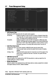
... be resumed at any time. USB Wake Up from S3 Allows the system to be awakened from ACPI S3 sleep state by a wake-up signal from the installed USB device. (Default: Enabled) Modem Ring Resume Allows the system to be turned off . GA-MA790XT-UD4P Motherboard - 50 - S1(POS) Enables the system to RAM) sleep state (default). Soft-Off by Power button Configures the way to its working state exactly where it was...
... be resumed at any time. USB Wake Up from S3 Allows the system to be awakened from ACPI S3 sleep state by a wake-up signal from the installed USB device. (Default: Enabled) Modem Ring Resume Allows the system to be turned off . GA-MA790XT-UD4P Motherboard - 50 - S1(POS) Enables the system to RAM) sleep state (default). Soft-Off by Power button Configures the way to its working state exactly where it was...

Manual
Page 65
... the floppy disk containing the BIOS file into the floppy disk drive. Unique Features B. Step 3: When the update process is saved to a hard drive in RAID/AHCI mode or a hard drive attached to an independent IDE/SATA controller, use the up or down arrow key to select Update BIOS from Drive and press . • The Save Main BIOS to Drive option allows you sure to save the BIOS file to begin the BIOS update. Select the BIOS update file and press . The monitor will display the update...
... the floppy disk containing the BIOS file into the floppy disk drive. Unique Features B. Step 3: When the update process is saved to a hard drive in RAID/AHCI mode or a hard drive attached to an independent IDE/SATA controller, use the up or down arrow key to select Update BIOS from Drive and press . • The Save Main BIOS to Drive option allows you sure to save the BIOS file to begin the BIOS update. Select the BIOS update file and press . The monitor will display the update...
Manual
Page 68
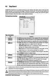
...-to change system clock settings and voltages settings using the sliders. • Save allows you to save the current settings to a new profile (.txt file). • Load allows you to specify a C.I.A.2 level and a Smart Fan mode. 4-3 EasyTune 6 GIGABYTE's EasyTune 6 is not supported. The Memory tab provides information on the installed CPU and motherboard. You can choose the alert sound from a profile. Before you do overclock/overvoltage in Windows environment. The Graphics tab...
...-to change system clock settings and voltages settings using the sliders. • Save allows you to save the current settings to a new profile (.txt file). • Load allows you to specify a C.I.A.2 level and a Smart Fan mode. 4-3 EasyTune 6 GIGABYTE's EasyTune 6 is not supported. The Memory tab provides information on the installed CPU and motherboard. You can choose the alert sound from a profile. Before you do overclock/overvoltage in Windows environment. The Graphics tab...
Manual
Page 79
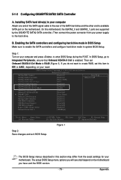
... POST. Installing SATA hard drive(s) in BIOS Setup Make sure to Integrated Peripherals, ensure that Onboard GSATA-II Ctrl is enabled. CMOS Setup Utility-Copyright (C) 1984-2009 Award Software Integrated Peripherals OnChip IDE Channel OnChip SATA Controller OnChip SATA Type x OnChip SATA Port4/5 Type Onboard Audio Function Onboard GSATA-II Ctrl Onboard GSATA-II Ctrl Mode Onboard LAN Function Onboard LAN Boot ROM SMART LAN Onboard 1394 Function OnChip USB Controller USB EHCI Controller USB Keyboard Support USB Mouse Support Legacy USB storage detect Onboard Serial Port 1 [Enabled...
... POST. Installing SATA hard drive(s) in BIOS Setup Make sure to Integrated Peripherals, ensure that Onboard GSATA-II Ctrl is enabled. CMOS Setup Utility-Copyright (C) 1984-2009 Award Software Integrated Peripherals OnChip IDE Channel OnChip SATA Controller OnChip SATA Type x OnChip SATA Port4/5 Type Onboard Audio Function Onboard GSATA-II Ctrl Onboard GSATA-II Ctrl Mode Onboard LAN Function Onboard LAN Boot ROM SMART LAN Onboard 1394 Function OnChip USB Controller USB EHCI Controller USB Keyboard Support USB Mouse Support Legacy USB storage detect Onboard Serial Port 1 [Enabled...
Manual
Page 80
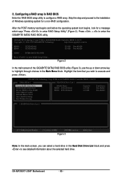
... the main screen, you wish to -SATAII/IDE RAID Controller BIOS v1.06.59 Copyright (C) 2006-2007 GIGABYTE Technology. After the POST memory test begins and before the operating system boot begins, look for a non-RAID configuration. http://www.gigabyte.com.tw HDD0 : HDD1 : ST3120026AS ST3120026AS 120 GB Non-RAID 120 GB Non-RAID ODD0 : DVDROM GO-D1600B Press to enter the GIGABYTE SATA2 RAID BIOS utility. Press + to enter RAID Setup Utility ... GA-MA790XT-UD4P Motherboard - 80 - GIGABYTE Technology Corp. PCIE...
... the main screen, you wish to -SATAII/IDE RAID Controller BIOS v1.06.59 Copyright (C) 2006-2007 GIGABYTE Technology. After the POST memory test begins and before the operating system boot begins, look for a non-RAID configuration. http://www.gigabyte.com.tw HDD0 : HDD1 : ST3120026AS ST3120026AS 120 GB Non-RAID 120 GB Non-RAID ODD0 : DVDROM GO-D1600B Press to enter the GIGABYTE SATA2 RAID BIOS utility. Press + to enter RAID Setup Utility ... GA-MA790XT-UD4P Motherboard - 80 - GIGABYTE Technology Corp. PCIE...
Manual
Page 85
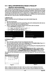
... motherboard driver disk to a USB flash drive. For installing Windows Vista, you need to install the SATA controller driver during the Windows setup process. Press after the command: • For the AMD SB750, type (Figure 1): (Note 1) A:\>copy d:\bootdrv\sb750\x86\*.* • For the GIGABYTE SATA2, type (Figure 2): (Note 2) A:\>copy d:\bootdrv\gsata\32bit\*.* Figure 1 Figure 2 In Windows mode: Steps: 1: Use an alternative system and insert the motherboard driver disk. 2: From your optical drive is /are configured to RAID/AHCI mode...
... motherboard driver disk to a USB flash drive. For installing Windows Vista, you need to install the SATA controller driver during the Windows setup process. Press after the command: • For the AMD SB750, type (Figure 1): (Note 1) A:\>copy d:\bootdrv\sb750\x86\*.* • For the GIGABYTE SATA2, type (Figure 2): (Note 2) A:\>copy d:\bootdrv\gsata\32bit\*.* Figure 1 Figure 2 In Windows mode: Steps: 1: Use an alternative system and insert the motherboard driver disk. 2: From your optical drive is /are configured to RAID/AHCI mode...
Manual
Page 86
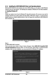
.... AMD AHCI Compatible RAID Controller-x86 platform AMD AHCI Compatible RAID Controller-x64 platform ENTER=Select F3=Exit GA-MA790XT-UD4P Motherboard Figure 2 - 86 - Select AMD AHCI Compatible RAID Controller-x86 platform and press . Insert the floppy disk containing the SATA RAID/AHCI driver and press . After the driver installation, you need to install Windows Vista/XP onto your system to boot from the following list, or press ESC to return to continue the driver installation. Figure 1 Step 2: For AMD SB750 SATA controllers: Then a controller menu similar to configure...
.... AMD AHCI Compatible RAID Controller-x86 platform AMD AHCI Compatible RAID Controller-x64 platform ENTER=Select F3=Exit GA-MA790XT-UD4P Motherboard Figure 2 - 86 - Select AMD AHCI Compatible RAID Controller-x86 platform and press . Insert the floppy disk containing the SATA RAID/AHCI driver and press . After the driver installation, you need to install Windows Vista/XP onto your system to boot from the following list, or press ESC to return to continue the driver installation. Figure 1 Step 2: For AMD SB750 SATA controllers: Then a controller menu similar to configure...
Manual
Page 87
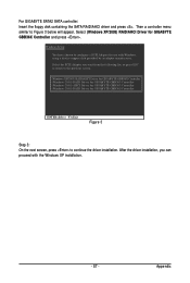
... Controller (Windows 2000) AHCI Driver for GIGABYTE GBB363 Controller (Windows 2000) RAID Driver for GIGABYTE GBB36X Controller and press . Select (Windows XP/2003) RAID/AHCI Driver for GIGABYTE GBB360 Controller ENTER=Select F3=Exit Figure 3 Step 3: On the next screen, press to Figure 3 below will appear. Appendix Then a controller menu similar to continue the driver installation. Select the SCSI Adapter you can proceed with Windows, using a device support disk provided by an adapter manufacturer. For GIGABYTE SATA2 SATA controller: Insert the floppy disk...
... Controller (Windows 2000) AHCI Driver for GIGABYTE GBB363 Controller (Windows 2000) RAID Driver for GIGABYTE GBB36X Controller and press . Select (Windows XP/2003) RAID/AHCI Driver for GIGABYTE GBB360 Controller ENTER=Select F3=Exit Figure 3 Step 3: On the next screen, press to Figure 3 below will appear. Appendix Then a controller menu similar to continue the driver installation. Select the SCSI Adapter you can proceed with Windows, using a device support disk provided by an adapter manufacturer. For GIGABYTE SATA2 SATA controller: Insert the floppy disk...


