Manual
Page 3
... the specifications and features in the use of this product, GIGABYTE provides the following types of documentations: For quick set-up of the motherboard is protected by GIGABYTE without GIGABYTE's prior written permission. Changes to their respective owners. For ...Downloads\Motherboard\Technology Guide page on your motherboard revision before updating motherboard BIOS, drivers, or when looking for technical information. The trademarks mentioned in this manual is 1.0. No part of GIGABYTE. All rights reserved. Disclaimer Information in this manual may be ...
... the specifications and features in the use of this product, GIGABYTE provides the following types of documentations: For quick set-up of the motherboard is protected by GIGABYTE without GIGABYTE's prior written permission. Changes to their respective owners. For ...Downloads\Motherboard\Technology Guide page on your motherboard revision before updating motherboard BIOS, drivers, or when looking for technical information. The trademarks mentioned in this manual is 1.0. No part of GIGABYTE. All rights reserved. Disclaimer Information in this manual may be ...
Manual
Page 4
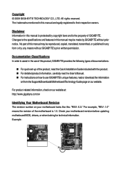
Table of Contents Box Contents ...6 OptionalItems ...6 GA-MA790X-UD3P Motherboard Layout 7 Block Diagram ...8 Chapter 1 Hardware Installation 9 1-1 Installation Precautions 9 1-2 Product Specifications 10 1-3 Installing the CPU and CPU Cooler ...of ATI CrossFireXTM Configuration 19 1-7 Back Panel Connectors 20 1-8 Internal Connectors 22 Chapter 2 BIOS Setup 33 2-1 Startup Screen 34 2-2 The Main Menu 35 2-3 MB Intelligent Tweaker(M.I.T 37 2-4 Standard CMOS Features 43 2-5 Advanced BIOS Features 45 2-6 IntegratedPeripherals 47 2-7 Power Management Setup 50 2-8 PC Health Status 52 ...
Table of Contents Box Contents ...6 OptionalItems ...6 GA-MA790X-UD3P Motherboard Layout 7 Block Diagram ...8 Chapter 1 Hardware Installation 9 1-1 Installation Precautions 9 1-2 Product Specifications 10 1-3 Installing the CPU and CPU Cooler ...of ATI CrossFireXTM Configuration 19 1-7 Back Panel Connectors 20 1-8 Internal Connectors 22 Chapter 2 BIOS Setup 33 2-1 Startup Screen 34 2-2 The Main Menu 35 2-3 MB Intelligent Tweaker(M.I.T 37 2-4 Standard CMOS Features 43 2-5 Advanced BIOS Features 45 2-6 IntegratedPeripherals 47 2-7 Power Management Setup 50 2-8 PC Health Status 52 ...
Manual
Page 5
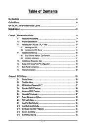
... ...59 3-6 Download Center 60 Chapter 4 Unique Features 61 4-1 Xpress Recovery2 61 4-2 BIOS Update Utilities 64 4-2-1 Updating the BIOS with the Q-Flash Utility 64 4-2-2 Updating the BIOS with the @BIOS Utility 67 4-3 EasyTune 6 ...68 4-4 Easy Energy Saver 69 4-5 Q-Share ...71 ...4-6 Time Repair ...72 Chapter 5 Appendix ...73 5-1 Configuring SATA Hard Drive(s 73 5-1-1 Configuring AMD SB750 SATA Controllers 73 5-1-2 Configuring GIGABYTE...
... ...59 3-6 Download Center 60 Chapter 4 Unique Features 61 4-1 Xpress Recovery2 61 4-2 BIOS Update Utilities 64 4-2-1 Updating the BIOS with the Q-Flash Utility 64 4-2-2 Updating the BIOS with the @BIOS Utility 67 4-3 EasyTune 6 ...68 4-4 Easy Energy Saver 69 4-5 Q-Share ...71 ...4-6 Time Repair ...72 Chapter 5 Appendix ...73 5-1 Configuring SATA Hard Drive(s 73 5-1-1 Configuring AMD SB750 SATA Controllers 73 5-1-2 Configuring GIGABYTE...
Manual
Page 8
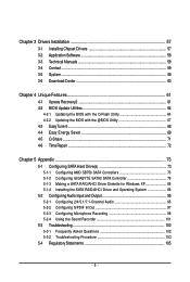
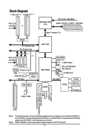
... PCI Express Bus x1 x1 x1 x1 PCIe CLK (100 MHz) 3 PCI Express x1 RJ45 RTL8111C LAN 2 SATA 3Gb/s PCI Bus GIGABYTE SATA2 TSB43AB23 AMD 790X AMD SB750 Dual BIOS 6 SATA 3Gb/s ATA-133/100/66/33 IDE Channel 12 USB Ports CODEC LPC BUS IT8720 Floppy COM Port PS/2 KB/Mouse...
... PCI Express Bus x1 x1 x1 x1 PCIe CLK (100 MHz) 3 PCI Express x1 RJ45 RTL8111C LAN 2 SATA 3Gb/s PCI Bus GIGABYTE SATA2 TSB43AB23 AMD 790X AMD SB750 Dual BIOS 6 SATA 3Gb/s ATA-133/100/66/33 IDE Channel 12 USB Ports CODEC LPC BUS IT8720 Floppy COM Port PS/2 KB/Mouse...
Manual
Page 11
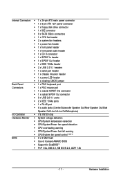
... CPU/System/Power fan speed detection CPU overheating warning CPU/System/Power fan fail warning CPU/System fan speed control (Note 4) BIOS 2 x 8 Mbit flash Use of licensed AWARD BIOS Support for DualBIOSTM PnP 1.0a, DMI 2.0, SM...
... CPU/System/Power fan speed detection CPU overheating warning CPU/System/Power fan fail warning CPU/System fan speed control (Note 4) BIOS 2 x 8 Mbit flash Use of licensed AWARD BIOS Support for DualBIOSTM PnP 1.0a, DMI 2.0, SM...
Manual
Page 12
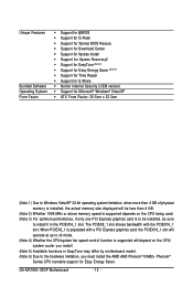
... supported will be less than 4 GB of physical memory is populated with the PCIEX16_1 slot. GA-MA790X-UD3P Motherboard - 12 - Unique Features Bundled Software Operating System Form Factor Support for @BIOS Support for Q-Flash Support for Xpress BIOS Rescue Support for Download Center Support for Xpress Install Support for...
... supported will be less than 4 GB of physical memory is populated with the PCIEX16_1 slot. GA-MA790X-UD3P Motherboard - 12 - Unique Features Bundled Software Operating System Form Factor Support for @BIOS Support for Q-Flash Support for Xpress BIOS Rescue Support for Download Center Support for Xpress Install Support for...
Manual
Page 16
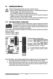
...same capacity, brand, speed, and chips be installed in Dual Channel mode. 1. GA-MA790X-UD3P Motherboard - 16 - Enabling Dual Channel memory mode will automatically detect the specifications and...When enabling Dual Channel mode with two or four memory modules, it is installed, the BIOS will double the original memory bandwidth. DDR2_1 DDR2_2 DDR2_3 DDR2_4 Due to CPU limitation, ...DS/SS - - - - - - - - A memory module can be used . (Go to GIGABYTE's website for optimum performance. 1-4 Installing the Memory Read the following guidelines before you begin to install the ...
...same capacity, brand, speed, and chips be installed in Dual Channel mode. 1. GA-MA790X-UD3P Motherboard - 16 - Enabling Dual Channel memory mode will automatically detect the specifications and...When enabling Dual Channel mode with two or four memory modules, it is installed, the BIOS will double the original memory bandwidth. DDR2_1 DDR2_2 DDR2_3 DDR2_4 Due to CPU limitation, ...DS/SS - - - - - - - - A memory module can be used . (Go to GIGABYTE's website for optimum performance. 1-4 Installing the Memory Read the following guidelines before you begin to install the ...
Manual
Page 18
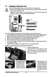
... the expansion slot. 1. Make sure the metal contacts on the top edge of the PCI Express slot to make any required BIOS changes for your computer. If necessary, go to BIOS Setup to release the card and then pull the card straight up from the slot. Make sure the card is fully... the steps below to the chassis back panel with the slot, and press down on the card are completely inserted into the PCI Express slot. GA-MA790X-UD3P Motherboard - 18 - • Removing the Card from the PCIEX8_1 Slot: Press the white latch at the end of the card until it is fully inserted...
... the expansion slot. 1. Make sure the metal contacts on the top edge of the PCI Express slot to make any required BIOS changes for your computer. If necessary, go to BIOS Setup to release the card and then pull the card straight up from the slot. Make sure the card is fully... the steps below to the chassis back panel with the slot, and press down on the card are completely inserted into the PCI Express slot. GA-MA790X-UD3P Motherboard - 18 - • Removing the Card from the PCIEX8_1 Slot: Press the white latch at the end of the card until it is fully inserted...
Manual
Page 27
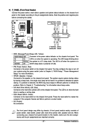
...LED Connects to the speaker on the chassis front panel. PW+ PWSPEAK+ SPEAK- 2 20 1 19 HD+ HD- The LED is detected, the BIOS may differ by issuing a beep code. Hardware Installation Message/Power/ Power Sleep LED Switch Speaker MSG+ MSG- Press the reset switch to restart the ...LED keeps blinking when S1 Blinking the system is detected at system startup. When connecting your system using the power switch (refer to Chapter 2, "BIOS Setup," "Power Management Setup," for information about beep codes. • HD (Hard Drive Activity LED, Blue) Connects to the hard drive activity ...
...LED Connects to the speaker on the chassis front panel. PW+ PWSPEAK+ SPEAK- 2 20 1 19 HD+ HD- The LED is detected, the BIOS may differ by issuing a beep code. Hardware Installation Message/Power/ Power Sleep LED Switch Speaker MSG+ MSG- Press the reset switch to restart the ...LED keeps blinking when S1 Blinking the system is detected at system startup. When connecting your system using the power switch (refer to Chapter 2, "BIOS Setup," "Power Management Setup," for information about beep codes. • HD (Hard Drive Activity LED, Blue) Connects to the hard drive activity ...
Manual
Page 32
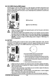
... to touch the positive and negative terminals of purchase or local dealer if you are not able to remove the jumper cap from the jumper. GA-MA790X-UD3P Motherboard - 32 - Danger of explosion if the battery is turned off your computer, be sure to replace the battery by removing the battery: 1....side should face up). • Used batteries must be lost. Replace the battery when the battery voltage drops to keep the values (such as BIOS configurations, date, and time information) in the CMOS when the computer is replaced with an incorrect model. • Contact the place of the ...
... to touch the positive and negative terminals of purchase or local dealer if you are not able to remove the jumper cap from the jumper. GA-MA790X-UD3P Motherboard - 32 - Danger of explosion if the battery is turned off your computer, be sure to replace the battery by removing the battery: 1....side should face up). • Used batteries must be lost. Replace the battery when the battery voltage drops to keep the values (such as BIOS configurations, date, and time information) in the CMOS when the computer is replaced with an incorrect model. • Contact the place of the ...
Manual
Page 33
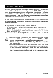
...8226; BIOS will emit a beep code during the POST. BIOS includes a BIOS Setup program that searches and downloads the latest version of BIOS from the Internet and updates the BIOS. Inadequately altering the settings may result in the CMOS on . To upgrade the BIOS, use either the GIGABYTE Q-Flash or @BIOS utility... It is recommended that you not alter the default settings (unless you not flash the BIOS. Chapter 2 BIOS Setup BIOS (Basic Input and Output System) records hardware parameters of the BIOS Setup program. When the power is a Windows-based utility that allows the user to ...
...8226; BIOS will emit a beep code during the POST. BIOS includes a BIOS Setup program that searches and downloads the latest version of BIOS from the Internet and updates the BIOS. Inadequately altering the settings may result in the CMOS on . To upgrade the BIOS, use either the GIGABYTE Q-Flash or @BIOS utility... It is recommended that you not alter the default settings (unless you not flash the BIOS. Chapter 2 BIOS Setup BIOS (Basic Input and Output System) records hardware parameters of the BIOS Setup program. When the power is a Windows-based utility that allows the user to ...
Manual
Page 34
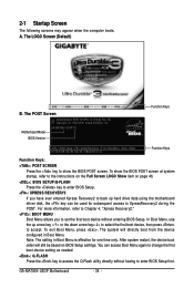
... RECOVERY2 If you to set the first boot device without having to the instructions on the Full Screen LOGO Show item on BIOS Setup settings. Motherboard Model BIOS Version GA-MA790X-UD3P D2 . . . . : BIOS Setup : XpressRecovery2 : Boot Menu : Qflash 04/22/2009-RD790-SB750-7A66AG0CC-00 Function Keys Function Keys Function Keys: : POST SCREEN Press the...
... RECOVERY2 If you to set the first boot device without having to the instructions on the Full Screen LOGO Show item on BIOS Setup settings. Motherboard Model BIOS Version GA-MA790X-UD3P D2 . . . . : BIOS Setup : XpressRecovery2 : Boot Menu : Qflash 04/22/2009-RD790-SB750-7A66AG0CC-00 Function Keys Function Keys Function Keys: : POST SCREEN Press the...

Manual
Page 35
.... • When the system is displayed on the bottom line of function keys available for reference only and may differ by BIOS version. - 35 - BIOS Setup Program Function Keys Move the selection bar to select an item Execute command or enter the submenu Main Menu: Exit the...(General Help) of the Main Menu. Help for each item is in a submenu, press to BIOS Load CMOS from BIOS Time, Date, Hard Disk Type... BIOS Setup Press to BIOS F12: Load CMOS from BIOS Main Menu Help The onscreen description of a highlighted setup option is not stable as usual, select the...
.... • When the system is displayed on the bottom line of function keys available for reference only and may differ by BIOS version. - 35 - BIOS Setup Program Function Keys Move the selection bar to select an item Execute command or enter the submenu Main Menu: Exit the...(General Help) of the Main Menu. Help for each item is in a submenu, press to BIOS Load CMOS from BIOS Time, Date, Hard Disk Type... BIOS Setup Press to BIOS F12: Load CMOS from BIOS Main Menu Help The onscreen description of a highlighted setup option is not stable as usual, select the...
Manual
Page 36
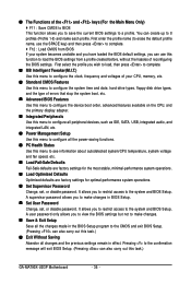
...remain in effect. A user password only allows you to view the BIOS settings but not to make changes in the BIOS Setup program to the confirmation message will exit BIOS Setup. (Pressing can also carry out this task.) GA-MA790X-UD3P Motherboard - 36 - It allows you to restrict access to a ...profile. The Functions of the and keys (For the Main Menu Only) F11 : Save CMOS to BIOS This function allows you...
...remain in effect. A user password only allows you to view the BIOS settings but not to make changes in the BIOS Setup program to the confirmation message will exit BIOS Setup. (Pressing can also carry out this task.) GA-MA790X-UD3P Motherboard - 36 - It allows you to restrict access to a ...profile. The Functions of the and keys (For the Main Menu Only) F11 : Save CMOS to BIOS This function allows you...
Manual
Page 37
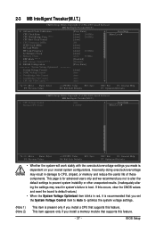
... is present only if you install a memory module that supports this feature. - 37 - This item appears only if you install a CPU that supports this feature. BIOS Setup Incorrectly doing overclock/overvoltage may result in red, it is dependent on your overall system configurations.
... is present only if you install a memory module that supports this feature. - 37 - This item appears only if you install a CPU that supports this feature. BIOS Setup Incorrectly doing overclock/overvoltage may result in red, it is dependent on your overall system configurations.
Manual
Page 38
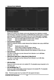
.... (Note) Allows you to alter the North Bridge controller frequency for all CPU cores. GA-MA790X-UD3P Motherboard - 38 - After the selection, select Save & Exit Setup in the BIOS Main Menu and then press Y. Wait for the settings to take effect. Disabled Disables this... specific AMD EC firmware version. Per Core Individually configures Advanced Clock Calibration for the installed CPU. A message which says "BIOS Is Updating EC Firmware!!! Advanced Clock Calibratioin CMOS Setup Utility-Copyright (C) 1984-2009 Award Software Advanced Clock Calibratioin EC Firmware Selection...
.... (Note) Allows you to alter the North Bridge controller frequency for all CPU cores. GA-MA790X-UD3P Motherboard - 38 - After the selection, select Save & Exit Setup in the BIOS Main Menu and then press Y. Wait for the settings to take effect. Disabled Disables this... specific AMD EC firmware version. Per Core Individually configures Advanced Clock Calibration for the installed CPU. A message which says "BIOS Is Updating EC Firmware!!! Advanced Clock Calibratioin CMOS Setup Utility-Copyright (C) 1984-2009 Award Software Advanced Clock Calibratioin EC Firmware Selection...
Manual
Page 39
...100 MHz to manually set in accordance with the CPU specifications. Important It is highly recommended that supports this feature. - 39 - Auto lets BIOS automatically set to 500 MHz. Auto sets the PCIe clock frequency to standard 100 MHz. (Default: Auto) HT Link Width Allows you to ... Frequency (Mhz) item below to be configurable. When you use a AM2 CPU: DDR 400 Sets Memory Clock to 16 bit. Normal Lets BIOS optimize memory voltage settings. (Default) By EPP Sets memory voltage according to X2.00. Set Memory Clock Determines whether to 200 MHz. The ...
...100 MHz to manually set in accordance with the CPU specifications. Important It is highly recommended that supports this feature. - 39 - Auto lets BIOS automatically set to 500 MHz. Auto sets the PCIe clock frequency to standard 100 MHz. (Default: Auto) HT Link Width Allows you to ... Frequency (Mhz) item below to be configurable. When you use a AM2 CPU: DDR 400 Sets Memory Clock to 16 bit. Normal Lets BIOS optimize memory voltage settings. (Default) By EPP Sets memory voltage according to X2.00. Set Memory Clock Determines whether to 200 MHz. The ...
Manual
Page 41
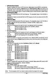
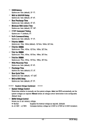
...default), 3T~6T. Write Recovery Time Options are : Auto (default), 3T~6T. RAS to RAS Delay Options are : Auto (default), 3T~7T. Auto lets BIOS automatically set the system voltages as required. (Default) +0.100V ~ +0.700V Increases memory voltage by 0.100V to set the system voltages. CAS# latency Options are ... RAS to CAS R/W Delay Options are : Auto (default), 11T~26T. Trfc1 for DIMM4 Options are : 75ns, 105ns, 127.5ns, 195ns, 327.5ns. BIOS Setup Minimum RAS Active Time Options are: Auto (default), 5T~18T. 1T/2T Command Timing Options are : 75ns, 105ns, 127.5ns, 195ns, 327.5ns...
...default), 3T~6T. Write Recovery Time Options are : Auto (default), 3T~6T. RAS to RAS Delay Options are : Auto (default), 3T~7T. Auto lets BIOS automatically set the system voltages as required. (Default) +0.100V ~ +0.700V Increases memory voltage by 0.100V to set the system voltages. CAS# latency Options are ... RAS to CAS R/W Delay Options are : Auto (default), 11T~26T. Trfc1 for DIMM4 Options are : 75ns, 105ns, 127.5ns, 195ns, 327.5ns. BIOS Setup Minimum RAS Active Time Options are: Auto (default), 5T~18T. 1T/2T Command Timing Options are : 75ns, 105ns, 127.5ns, 195ns, 327.5ns...

Manual
Page 43
...43 - IDE Channel 0, 1 Master/Slave Configure your IDE/SATA devices by using one of the two methods below : • Auto Lets the BIOS automatically detect IDE/SATA devices during the POST for faster system startup. IDE Channel 2, 3, 4 Master/Slave IDE Auto-Detection Press to autodetect the parameters... of the IDE/SATA device on this item to set this channel. BIOS Setup For example, 1 p.m. IDE Channel 0, 1 Master/Slave IDE HDD Auto-Detection Press to autodetect the parameters of the IDE/SATA device...
...43 - IDE Channel 0, 1 Master/Slave Configure your IDE/SATA devices by using one of the two methods below : • Auto Lets the BIOS automatically detect IDE/SATA devices during the POST for faster system startup. IDE Channel 2, 3, 4 Master/Slave IDE Auto-Detection Press to autodetect the parameters... of the IDE/SATA device on this item to set this channel. BIOS Setup For example, 1 p.m. IDE Channel 0, 1 Master/Slave IDE HDD Auto-Detection Press to autodetect the parameters of the IDE/SATA device...
Manual
Page 44
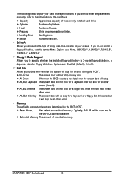
...not install a floppy disk drive, set this item to the information on the hard drive. Options are determined by the BIOS POST. Landing Zone Landing zone. No Errors The system boot will stop for the MS-DOS operating system. All Errors Whenever the... BIOS detects a non-fatal error the system boot will not stop for an error during the POST. Memory These fields are read-only and are : None, 360K/5.25", 1.2M/5.25", 720K/3.5", 1.44M/3.5", 2.88M/3.5". GA-MA790X-UD3P Motherboard - 44 - Precomp Write precompensation...
...not install a floppy disk drive, set this item to the information on the hard drive. Options are determined by the BIOS POST. Landing Zone Landing zone. No Errors The system boot will stop for the MS-DOS operating system. All Errors Whenever the... BIOS detects a non-fatal error the system boot will not stop for an error during the POST. Memory These fields are read-only and are : None, 360K/5.25", 1.2M/5.25", 720K/3.5", 1.44M/3.5", 2.88M/3.5". GA-MA790X-UD3P Motherboard - 44 - Precomp Write precompensation...


