Manual
Page 4
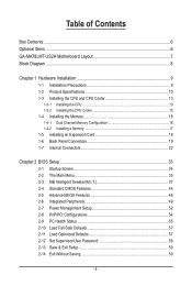
Table of Contents Box Contents...6 Optional Items...6 GA-MA78LMT-US2H Motherboard Layout 7 Block Diagram...8 Chapter 1 Hardware Installation 9 1-1 Installation Precautions 9 1-2 Product Specifications 10 1-3 Installing the CPU and CPU Cooler 13 1-3-1 Installing the CPU 13 1-3-2 Installing the CPU Cooler 15 1-4 Installing the Memory 16 1-4-1 Dual Channel Memory Configuration 16 1-4-2 Installing a Memory 17 1-5 Installing an Expansion Card 18 1-6 Back Panel...
Table of Contents Box Contents...6 Optional Items...6 GA-MA78LMT-US2H Motherboard Layout 7 Block Diagram...8 Chapter 1 Hardware Installation 9 1-1 Installation Precautions 9 1-2 Product Specifications 10 1-3 Installing the CPU and CPU Cooler 13 1-3-1 Installing the CPU 13 1-3-2 Installing the CPU Cooler 15 1-4 Installing the Memory 16 1-4-1 Dual Channel Memory Configuration 16 1-4-2 Installing a Memory 17 1-5 Installing an Expansion Card 18 1-6 Back Panel...

Manual
Page 8
Block Diagram PCIe CLK (100 MHz) 1 PCI Express x16 CPU CLK+/- (200 MHz) AM3 CPU DDR3 1666 (O.C.)/1333/1066 MHz Dual Channel Memory Hyper Transport 3.0 PCI Express x16 PCI Express Bus x1 PCIe CLK (100 MHz) 1 PCI Express x1 RTL8111D RJ45 LAN Dual BIOS PCI Bus AMD 760G ...
Block Diagram PCIe CLK (100 MHz) 1 PCI Express x16 CPU CLK+/- (200 MHz) AM3 CPU DDR3 1666 (O.C.)/1333/1066 MHz Dual Channel Memory Hyper Transport 3.0 PCI Express x16 PCI Express Bus x1 PCIe CLK (100 MHz) 1 PCI Express x1 RTL8111D RJ45 LAN Dual BIOS PCI Bus AMD 760G ...
Manual
Page 9
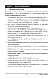
... 1-1 Installation Precautions The motherboard contains numerous delicate electronic circuits and components which can lead to damage to system components as well as a motherboard, CPU or memory. Hardware Installation These stickers are connected tightly and securely. • When handling the motherboard, avoid touching any installation steps or have it on top of...
... 1-1 Installation Precautions The motherboard contains numerous delicate electronic circuits and components which can lead to damage to system components as well as a motherboard, CPU or memory. Hardware Installation These stickers are connected tightly and securely. • When handling the motherboard, avoid touching any installation steps or have it on top of...
Manual
Page 10
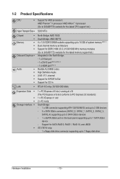
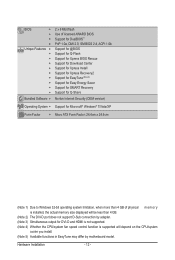
...™ II processor/ AMD Athlon™ II processor (Go to GIGABYTE's website for the latest CPU support list.) Hyper Transport Bus 5200 MT/s Chipset Memory Onboard Graphics Audio ...AMD SB710 4 x 1.5V DDR3 DIMM sockets supporting up to 16 GB of system memory (Note 1) Dual channel memory architecture Support for DDR3 1666 (O.C.)/1333/1066 MHz memory modules (Go to GIGABYTE's website for the latest memory support list.) Integrated in the North Bridge: - 1 x D-Sub port - ...
...™ II processor/ AMD Athlon™ II processor (Go to GIGABYTE's website for the latest CPU support list.) Hyper Transport Bus 5200 MT/s Chipset Memory Onboard Graphics Audio ...AMD SB710 4 x 1.5V DDR3 DIMM sockets supporting up to 16 GB of system memory (Note 1) Dual channel memory architecture Support for DDR3 1666 (O.C.)/1333/1066 MHz memory modules (Go to GIGABYTE's website for the latest memory support list.) Integrated in the North Bridge: - 1 x D-Sub port - ...
Manual
Page 12
... Form Factor; 24.4cm x 24.4cm (Note 1) Due to Windows 32-bit operating system limitation, when more than 4 GB of physical m e m o r y is installed, the actual memory size displayed will be less than 4 GB. (Note 2) The DVI-D port does not support D-Sub connection by adapter. (Note 3) Simultaneous output for DVI-D and HDMI...
... Form Factor; 24.4cm x 24.4cm (Note 1) Due to Windows 32-bit operating system limitation, when more than 4 GB of physical m e m o r y is installed, the actual memory size displayed will be less than 4 GB. (Note 2) The DVI-D port does not support D-Sub connection by adapter. (Note 3) Simultaneous output for DVI-D and HDMI...

Manual
Page 13
...support list.) • Always turn on the computer if the CPU cooler is not recommended that the motherboard supports the CPU. (Go to GIGABYTE's website for the peripherals. age of the CPU may locate the notches on both sides of the CPU and alignment keys on the CPU...if oriented incorrectly. (Or you wish to set beyond the standard specifications, please do so according to your hardware specifications including the CPU, graphics card, memory, hard drive, etc. 1-3-1 Installing the CPU A. A Small Triangle Mark Denotes Pin One of the Socket AM3 Socket A Small Triangle Marking Denotes ...
...support list.) • Always turn on the computer if the CPU cooler is not recommended that the motherboard supports the CPU. (Go to GIGABYTE's website for the peripherals. age of the CPU may locate the notches on both sides of the CPU and alignment keys on the CPU...if oriented incorrectly. (Or you wish to set beyond the standard specifications, please do so according to your hardware specifications including the CPU, graphics card, memory, hard drive, etc. 1-3-1 Installing the CPU A. A Small Triangle Mark Denotes Pin One of the Socket AM3 Socket A Small Triangle Marking Denotes ...
Manual
Page 16
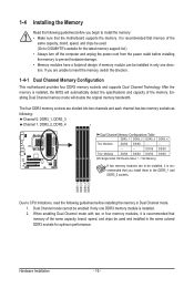
...Single-Sided, DS=Double-Sided, "- -"=No Memory) If two memory modules are to be used and installed in the DDR3_1 and DDR3_2 sockets. Hardware Installation - 16 - The four DDR3 memory sockets are unable to GIGABYTE's website for optimum performance. It is recommended... that the motherboard supports the memory. Enabling Dual Channel memory mode will automatically detect the specifications and capacity of the same...
...Single-Sided, DS=Double-Sided, "- -"=No Memory) If two memory modules are to be used and installed in the DDR3_1 and DDR3_2 sockets. Hardware Installation - 16 - The four DDR3 memory sockets are unable to GIGABYTE's website for optimum performance. It is recommended... that the motherboard supports the memory. Enabling Dual Channel memory mode will automatically detect the specifications and capacity of the same...
Manual
Page 17
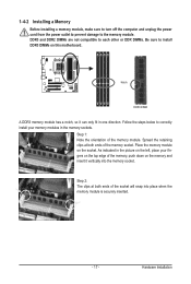
...on the socket. Step 2: The clips at both ends of the memory socket. Notch DDR3 DIMM A DDR3 memory module has a notch, so it can only fit in the picture on the memory and insert it vertically into place when the memory module is securely inserted. - 17 - Follow the steps below ...to correctly install your fingers on the top edge of the memory module. Step 1: Note the orientation of the memory, push down on the left, place your memory modules in the memory sockets. Place the memory module on this motherboard. DDR3 and DDR2 DIMMs are not compatible to each ...
...on the socket. Step 2: The clips at both ends of the memory socket. Notch DDR3 DIMM A DDR3 memory module has a notch, so it can only fit in the picture on the memory and insert it vertically into place when the memory module is securely inserted. - 17 - Follow the steps below ...to correctly install your fingers on the top edge of the memory module. Step 1: Note the orientation of the memory, push down on the left, place your memory modules in the memory sockets. Place the memory module on this motherboard. DDR3 and DDR2 DIMMs are not compatible to each ...
Manual
Page 20
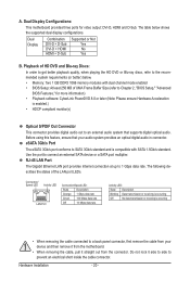
... Hardware Acceleration is occurring • When removing the cable connected to a back panel connector, first remove the cable from the connector. The table below . • Memory: Two 1 GB DDR3 1066 memory modules with SATA 1.5Gb/s standard.
... Hardware Acceleration is occurring • When removing the cable connected to a back panel connector, first remove the cable from the connector. The table below . • Memory: Two 1 GB DDR3 1066 memory modules with SATA 1.5Gb/s standard.
Manual
Page 36
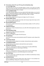
... Setup. First enter the profile name (to erase the default profile name, use this function to load the BIOS settings from BIOS If your CPU, memory, etc. Standard CMOS Features Use this menu to configure the system time and date, hard drive types, floppy disk drive types, and the type...
... Setup. First enter the profile name (to erase the default profile name, use this function to load the BIOS settings from BIOS If your CPU, memory, etc. Standard CMOS Features Use this menu to configure the system time and date, hard drive types, floppy disk drive types, and the type...
Manual
Page 37
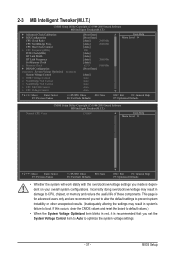
..., it is dependent on your overall system configurations. CPU Host Clock Control x CPU Frequency(MHz) PCIE Clock(MHz) HT Link Width HT Link Frequency Set Memory Clock x Memory Clock } DRAM Configuration ******** System Voltage Optimized ******** System Voltage Control x DDR3 Voltage Control x NorthBridge Volt Control x SouthBridge Volt Control x CPU NB VID Control x ...advanced users only and we recommend you made is recommended that you set the System Voltage Control item to Auto to CPU, chipset, or memory and reduce the useful life of these components.
..., it is dependent on your overall system configurations. CPU Host Clock Control x CPU Frequency(MHz) PCIE Clock(MHz) HT Link Width HT Link Frequency Set Memory Clock x Memory Clock } DRAM Configuration ******** System Voltage Optimized ******** System Voltage Control x DDR3 Voltage Control x NorthBridge Volt Control x SouthBridge Volt Control x CPU NB VID Control x ...advanced users only and we recommend you made is recommended that you set the System Voltage Control item to Auto to CPU, chipset, or memory and reduce the useful life of these components.
Manual
Page 39
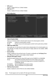
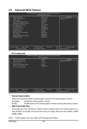
...F10: Save F6: Fail-Safe Defaults ESC: Exit F1: General Help F7: Optimized Defaults Internal Graphics Mode Allows you install a CPU that supports this memory for the onboard graphics controller from the D-SUB/DVI-D or D-SUB/HDMI. Options are: Auto (default), 128MB, 256MB, 512MB. troller. D-SUB... the control of VGA Core clock. (Default: Disabled) (Note) This item appears only if you to determine whether to allocate system memory for output, depending on to PEG and an ATI graphics card is installed. (Default: Disabled) Onboard VGA output connect Specifies the graphics...
...F10: Save F6: Fail-Safe Defaults ESC: Exit F1: General Help F7: Optimized Defaults Internal Graphics Mode Allows you install a CPU that supports this memory for the onboard graphics controller from the D-SUB/DVI-D or D-SUB/HDMI. Options are: Auto (default), 128MB, 256MB, 512MB. troller. D-SUB... the control of VGA Core clock. (Default: Disabled) (Note) This item appears only if you to determine whether to allocate system memory for output, depending on to PEG and an ATI graphics card is installed. (Default: Disabled) Onboard VGA output connect Specifies the graphics...
Manual
Page 40
...configurable only if the VGA Core Clock control option is from 200 MHz to 16 bit. Allows you to default values. X8.00 Sets Memory Clock to X4.00. The adjustable range is from 200 MHz to 2000 MHz. CPU Frequency(MHz) Allows you to alter the North Bridge... on the CPU being used . Manual allows the CPU Frequency (MHz) item below to be configurable. (Default: Auto) Memory Clock This option is configurable only when Set Memory Clock is highly recommended that the CPU frequency be configurable. The adjustable range is enabled. Auto BIOS will automatically adjust the...
...configurable only if the VGA Core Clock control option is from 200 MHz to 16 bit. Allows you to default values. X8.00 Sets Memory Clock to X4.00. The adjustable range is from 200 MHz to 2000 MHz. CPU Frequency(MHz) Allows you to alter the North Bridge... on the CPU being used . Manual allows the CPU Frequency (MHz) item below to be configurable. (Default: Auto) Memory Clock This option is configurable only when Set Memory Clock is highly recommended that the CPU frequency be configurable. The adjustable range is enabled. Auto BIOS will automatically adjust the...
Manual
Page 41
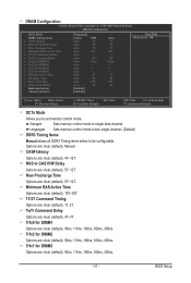
... mode to two single-channel. (Default) DDR3 Timing Items Manual allows all DDR3 Timing items below to set memory control mode. CAS# latency Options are : Auto (default), 1T, 2T. Minimum RAS Active Time Options are: Auto (default), 15T~30T. 1T/2T Command Timing Options...-Safe Defaults ESC: Exit F1: General Help F7: Optimized Defaults DCTs Mode Allows you to be configurable. Options are : Auto (default), 4T~7T. Ganged Sets memory control mode to CAS R/W Delay Options are : Auto (default), 90ns, 110ns, 160ns, 300ns, 350ns. Trfc0 for DIMM1 Options are : Auto (default), 5T~12T. RAS ...
... mode to two single-channel. (Default) DDR3 Timing Items Manual allows all DDR3 Timing items below to set memory control mode. CAS# latency Options are : Auto (default), 1T, 2T. Minimum RAS Active Time Options are: Auto (default), 15T~30T. 1T/2T Command Timing Options...-Safe Defaults ESC: Exit F1: General Help F7: Optimized Defaults DCTs Mode Allows you to be configurable. Options are : Auto (default), 4T~7T. Ganged Sets memory control mode to CAS R/W Delay Options are : Auto (default), 90ns, 110ns, 160ns, 300ns, 350ns. Trfc0 for DIMM1 Options are : Auto (default), 5T~12T. RAS ...

Manual
Page 42
...Recovery Time Options are : Auto (default), 11T~42T. RAS to set the South Bridge voltage. NorthBridge Volt Control Allows you to set memory voltage. Manual allows all voltage control items below to be configurable. (Default: Manual) DDR3 Voltage Control Allows you to set the North .... Normal Supplies the North Bridge voltage as required. BIOS Setup - 42 - Enabled allows the system to simultaneously access different channels of the memory to +0.750V. SouthBridge Volt Control Allows you to RAS Delay Options are: Auto (default), 4T~7T. Row Cycle Time Options are : ...
...Recovery Time Options are : Auto (default), 11T~42T. RAS to set the South Bridge voltage. NorthBridge Volt Control Allows you to set memory voltage. Manual allows all voltage control items below to be configurable. (Default: Manual) DDR3 Voltage Control Allows you to set the North .... Normal Supplies the North Bridge voltage as required. BIOS Setup - 42 - Enabled allows the system to simultaneously access different channels of the memory to +0.750V. SouthBridge Volt Control Allows you to RAS Delay Options are: Auto (default), 4T~7T. Row Cycle Time Options are : ...

Manual
Page 44
... 3 Master } IDE Channel 3 Slave [None] [None] [None] [None] [None] [None] [None] [None] Drive A Floppy 3 Mode Support [1.44M, 3.5"] [Disabled] Halt On [All, But Keyboard] Base Memory Extended Memory 640K 1790M Move Enter: Select F5: Previous Values +/-/PU/PD: Value F10: Save F6: Fail-Safe Defaults ESC: Exit F1: General Help F7: Optimized Defaults...
... 3 Master } IDE Channel 3 Slave [None] [None] [None] [None] [None] [None] [None] [None] Drive A Floppy 3 Mode Support [1.44M, 3.5"] [Disabled] Halt On [All, But Keyboard] Base Memory Extended Memory 640K 1790M Move Enter: Select F5: Previous Values +/-/PU/PD: Value F10: Save F6: Fail-Safe Defaults ESC: Exit F1: General Help F7: Optimized Defaults...

Manual
Page 45
...A Allows you to None. Floppy 3 Mode Support Allows you to the information on the hard drive. Memory These fields are read-only and are : Disabled (default), Drive A. Extended Memory The amount of cylinders. Sector Number of the currently installed hard drive. All, But Keyboard The system ...boot will not stop for an error during the POST. Base Memory Also called conventional memory. If you to determine whether the system will not stop for a keyboard error but stop . Options are determined by the ...
...A Allows you to None. Floppy 3 Mode Support Allows you to the information on the hard drive. Memory These fields are read-only and are : Disabled (default), Drive A. Extended Memory The amount of cylinders. Sector Number of the currently installed hard drive. All, But Keyboard The system ...boot will not stop for an error during the POST. Base Memory Also called conventional memory. If you to determine whether the system will not stop for a keyboard error but stop . Options are determined by the ...
Manual
Page 46
... Options are: Auto (default), 128MB, 256MB, 512MB. (Note) This item appears only if you to determine whether to allocate system memory for the onboard graphics controller. troller. MS-DOS, for example, will use only this feature. BIOS Setup - 46 - UMA Allocates... memory for the onboard graphics controller from the system memory. (Default) UMA Frame Buffer Size Frame buffer size is the total amount of system memory allocated solely for display. Capability Away Mode Backup BIOS Image to HDD Init...
... Options are: Auto (default), 128MB, 256MB, 512MB. (Note) This item appears only if you to determine whether to allocate system memory for the onboard graphics controller. troller. MS-DOS, for example, will use only this feature. BIOS Setup - 46 - UMA Allocates... memory for the onboard graphics controller from the system memory. (Default) UMA Frame Buffer Size Frame buffer size is the total amount of system memory allocated solely for display. Capability Away Mode Backup BIOS Image to HDD Init...

Manual
Page 53
... operating system. (Default: Enabled) Power On By Mouse Allows the system to be turned on upon the return of power from an AC power loss. Memory The system returns to let the system consume less than 1W power in a month. EuP Support Determines whether to its last known awake state upon...
... operating system. (Default: Enabled) Power On By Mouse Allows the system to be turned on upon the return of power from an AC power loss. Memory The system returns to let the system consume less than 1W power in a month. EuP Support Determines whether to its last known awake state upon...
Manual
Page 65
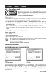
... of data). • It is recommended to back up your system to quickly compress and back up your system data and perform restoration of system memory • VESA compatible graphics card • Windows XP with Xpress Recovery cannot be restored using Xpress Recovery2. • USB hard drives are not supported. •...
... of data). • It is recommended to back up your system to quickly compress and back up your system data and perform restoration of system memory • VESA compatible graphics card • Windows XP with Xpress Recovery cannot be restored using Xpress Recovery2. • USB hard drives are not supported. •...


