Manual
Page 3
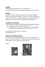
... by copyright laws and is 1.0. Example: For product-related information, check on our website at: http://www.gigabyte.com.tw Identifying Your Motherboard Revision The revision number on our website. Check your motherboard looks like this manual may be...For instructions on how to use GIGABYTE's unique features, read or download the information on/from the Support&Downloads\Motherboard\Technology Guide page on your motherboard revision before updating motherboard BIOS, drivers, or when looking for technical information. No part of GIGABYTE. All rights reserved. Copyright ...
... by copyright laws and is 1.0. Example: For product-related information, check on our website at: http://www.gigabyte.com.tw Identifying Your Motherboard Revision The revision number on our website. Check your motherboard looks like this manual may be...For instructions on how to use GIGABYTE's unique features, read or download the information on/from the Support&Downloads\Motherboard\Technology Guide page on your motherboard revision before updating motherboard BIOS, drivers, or when looking for technical information. No part of GIGABYTE. All rights reserved. Copyright ...
Manual
Page 4
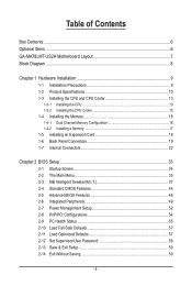
Table of Contents Box Contents...6 Optional Items...6 GA-MA78LMT-US2H Motherboard Layout 7 Block Diagram...8 Chapter 1 Hardware Installation 9 1-1 Installation Precautions 9 1-2 Product Specifications 10 1-3 Installing the CPU and CPU Cooler... Installing an Expansion Card 18 1-6 Back Panel Connectors 19 1-7 Internal Connectors 22 Chapter 2 BIOS Setup 33 2-1 Startup Screen 34 2-2 The Main Menu 35 2-3 MB Intelligent Tweaker(M.I.T 37 2-4 Standard CMOS Features 44 2-5 Advanced BIOS Features 46 2-6 Integrated Peripherals 49 2-7 Power Management Setup 52 2-8 PnP/PCI Configurations 54 ...
Table of Contents Box Contents...6 Optional Items...6 GA-MA78LMT-US2H Motherboard Layout 7 Block Diagram...8 Chapter 1 Hardware Installation 9 1-1 Installation Precautions 9 1-2 Product Specifications 10 1-3 Installing the CPU and CPU Cooler... Installing an Expansion Card 18 1-6 Back Panel Connectors 19 1-7 Internal Connectors 22 Chapter 2 BIOS Setup 33 2-1 Startup Screen 34 2-2 The Main Menu 35 2-3 MB Intelligent Tweaker(M.I.T 37 2-4 Standard CMOS Features 44 2-5 Advanced BIOS Features 46 2-6 Integrated Peripherals 49 2-7 Power Management Setup 52 2-8 PnP/PCI Configurations 54 ...
Manual
Page 5
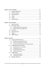
... 62 3-3 Technical Manuals 62 3-4 Contact...63 3-5 System...63 3-6 Download Center 64 Chapter 4 Unique Features 65 4-1 Xpress Recovery2 65 4-2 BIOS Update Utilities 68 4-2-1 Updating the BIOS with the Q-Flash Utility 68 4-2-2 Updating the BIOS with the @BIOS Utility 71 4-3 EasyTune 6...72 4-4 Easy Energy Saver 73 4-5 Q-Share...75 4-6 SMART Recovery 76 Chapter 5 Appendix...77 5-1 Configuring SATA...
... 62 3-3 Technical Manuals 62 3-4 Contact...63 3-5 System...63 3-6 Download Center 64 Chapter 4 Unique Features 65 4-1 Xpress Recovery2 65 4-2 BIOS Update Utilities 68 4-2-1 Updating the BIOS with the Q-Flash Utility 68 4-2-2 Updating the BIOS with the @BIOS Utility 71 4-3 EasyTune 6...72 4-4 Easy Energy Saver 73 4-5 Q-Share...75 4-6 SMART Recovery 76 Chapter 5 Appendix...77 5-1 Configuring SATA...

Manual
Page 8
.../1066 MHz Dual Channel Memory Hyper Transport 3.0 PCI Express x16 PCI Express Bus x1 PCIe CLK (100 MHz) 1 PCI Express x1 RTL8111D RJ45 LAN Dual BIOS PCI Bus AMD 760G GFX CLK (100 MHz) D-Sub DVI-D or HDMI (Note) 12 USB Ports AMD SB710 ATA-133/100/66/33 IDE Channel...
.../1066 MHz Dual Channel Memory Hyper Transport 3.0 PCI Express x16 PCI Express Bus x1 PCIe CLK (100 MHz) 1 PCI Express x1 RTL8111D RJ45 LAN Dual BIOS PCI Bus AMD 760G GFX CLK (100 MHz) D-Sub DVI-D or HDMI (Note) 12 USB Ports AMD SB710 ATA-133/100/66/33 IDE Channel...
Manual
Page 12
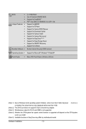
... w w w w w w w w w w Bundled Software w 2 x 8 Mbit flash Use of licensed AWARD BIOS Support for DualBIOS™ PnP 1.0a, DMI 2.0, SM BIOS 2.4, ACPI 1.0b Support for @BIOS Support for Q-Flash Support for Xpress BIOS Rescue Support for Download Center Support for Xpress Install Support for Xpress Recovery2 Support for EasyTune (Note 5) Support for Easy Energy Saver Support for...
... w w w w w w w w w w Bundled Software w 2 x 8 Mbit flash Use of licensed AWARD BIOS Support for DualBIOS™ PnP 1.0a, DMI 2.0, SM BIOS 2.4, ACPI 1.0b Support for @BIOS Support for Q-Flash Support for Xpress BIOS Rescue Support for Download Center Support for Xpress Install Support for Xpress Recovery2 Support for EasyTune (Note 5) Support for Easy Energy Saver Support for...
Manual
Page 16
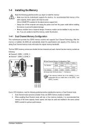
... install the memory: • Make sure that memory of the same capacity, brand, speed, and chips be used . (Go to GIGABYTE's website for optimum performance. DDR3_1 DDR3_2 DDR3_3 DDR3_4 Due to CPU limitations, read the following guidelines before installing the memory to prevent hardware damage.... 1-4-1 Dual Channel Memory Configuration This motherboard provides four DDR3 memory sockets and supports Dual Channel Technology. It is installed, the BIOS will double the original memory bandwidth. When enabling Dual Channel mode with two or four memory modules, it is recommended that memory...
... install the memory: • Make sure that memory of the same capacity, brand, speed, and chips be used . (Go to GIGABYTE's website for optimum performance. DDR3_1 DDR3_2 DDR3_3 DDR3_4 Due to CPU limitations, read the following guidelines before installing the memory to prevent hardware damage.... 1-4-1 Dual Channel Memory Configuration This motherboard provides four DDR3 memory sockets and supports Dual Channel Technology. It is installed, the BIOS will double the original memory bandwidth. When enabling Dual Channel mode with two or four memory modules, it is recommended that memory...
Manual
Page 18
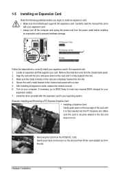
... expansion card. Secure the card's metal bracket to the chassis back panel with the expansion card in the slot. 3. If necessary, go to BIOS Setup to make any required BIOS changes for your computer. Install the driver provided with a screw. 5. Hardware Installation - 18 - Example: Installing and Removing a PCI Express Graphics Card: •...
... expansion card. Secure the card's metal bracket to the chassis back panel with the expansion card in the slot. 3. If necessary, go to BIOS Setup to make any required BIOS changes for your computer. Install the driver provided with a screw. 5. Hardware Installation - 18 - Example: Installing and Removing a PCI Express Graphics Card: •...
Manual
Page 20
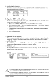
...connector. eSATA 3Gb/s Port The eSATA 3Gb/s port conforms to SATA 3Gb/s standard and is compatible with dual channel mode enabled • BIOS Setup: At least 256 MB of the LAN port LEDs. Use the port to 1 Gbps data rate. RJ-45 LAN Port The ... standard. Before using this feature, ensure that supports digital optical audio. The following describes the states of UMA Frame Buffer Size (refer to Chapter 2, "BIOS Setup," "Advanced BIOS Features," for video output: DVI-D, HDMI and D-Sub. Hardware Installation - 20 - Dual Display Combination DVI-D + D-Sub DVI-D + HDMI HDMI + ...
...connector. eSATA 3Gb/s Port The eSATA 3Gb/s port conforms to SATA 3Gb/s standard and is compatible with dual channel mode enabled • BIOS Setup: At least 256 MB of the LAN port LEDs. Use the port to 1 Gbps data rate. RJ-45 LAN Port The ... standard. Before using this feature, ensure that supports digital optical audio. The following describes the states of UMA Frame Buffer Size (refer to Chapter 2, "BIOS Setup," "Advanced BIOS Features," for video output: DVI-D, HDMI and D-Sub. Hardware Installation - 20 - Dual Display Combination DVI-D + D-Sub DVI-D + HDMI HDMI + ...
Manual
Page 27
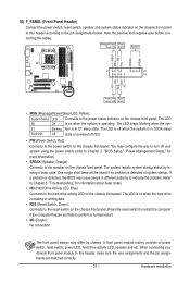
...System Status LED Connects to the power status indicator on the chassis front panel. The LED is off when the system is detected, the BIOS may issue beeps in different patterns to the hard drive activity LED on the chassis front panel. If a problem is in S1 sleep state.... When connecting your system using the power switch (refer to Chapter 2, "BIOS Setup," "Power Management Setup," for information about beep codes. • HD (Hard Drive Activity LED, Blue) Connects to indicate the problem. PW+ PWSPEAK+ ...
...System Status LED Connects to the power status indicator on the chassis front panel. The LED is off when the system is detected, the BIOS may issue beeps in different patterns to the hard drive activity LED on the chassis front panel. If a problem is in S1 sleep state.... When connecting your system using the power switch (refer to Chapter 2, "BIOS Setup," "Power Management Setup," for information about beep codes. • HD (Hard Drive Activity LED, Blue) Connects to indicate the problem. PW+ PWSPEAK+ ...
Manual
Page 31
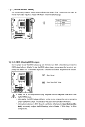
... may cause damage to the motherboard. • After system restart, go to BIOS Setup to load factory defaults (select Load Optimized Defaults) or manually configure the BIOS settings (refer to touch the two pins for BIOS configurations). - 31 - Open: Normal Short: Clear CMOS Values • Always...on the two pins to temporarily short the two pins or use a metal object like a screwdriver to Chapter 2, "BIOS Setup," for a few seconds. date information and BIOS configurations) and reset the CMOS values to remove the jumper cap from the jumper. Hardware Installation 17) CI (Chassis ...
... may cause damage to the motherboard. • After system restart, go to BIOS Setup to load factory defaults (select Load Optimized Defaults) or manually configure the BIOS settings (refer to touch the two pins for BIOS configurations). - 31 - Open: Normal Short: Clear CMOS Values • Always...on the two pins to temporarily short the two pins or use a metal object like a screwdriver to Chapter 2, "BIOS Setup," for a few seconds. date information and BIOS configurations) and reset the CMOS values to remove the jumper cap from the jumper. Hardware Installation 17) CI (Chassis ...
Manual
Page 32
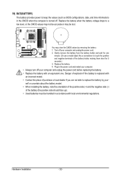
... and negative terminals of the battery holder, making them short for one minute. (Or use a metal object like a screwdriver to keep the values (such as BIOS configurations, date, and time information) in the CMOS when the computer is replaced with an incorrect model. • Contact the place of purchase or local...
... and negative terminals of the battery holder, making them short for one minute. (Or use a metal object like a screwdriver to keep the values (such as BIOS configurations, date, and time information) in the CMOS when the computer is replaced with an incorrect model. • Contact the place of purchase or local...
Manual
Page 33
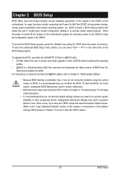
... unexpected results. Inadequately altering the settings may result in the CMOS. BIOS includes a BIOS Setup program that you need to) to boot. To upgrade the BIOS, use either the GIGABYTE Q-Flash or @BIOS utility. • Q-Flash allows the user to Chapter 4, "BIOS Update Utilities." • Because BIOS flashing is potentially risky, if you can press + in the...
... unexpected results. Inadequately altering the settings may result in the CMOS. BIOS includes a BIOS Setup program that you need to) to boot. To upgrade the BIOS, use either the GIGABYTE Q-Flash or @BIOS utility. • Q-Flash allows the user to Chapter 4, "BIOS Update Utilities." • Because BIOS flashing is potentially risky, if you can press + in the...
Manual
Page 34
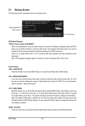
.... The system will still be used for one time only. Motherboard Model BIOS Version Award Modular BIOS v6.00PG, An Energy Star Ally Copyright (C) 1984-2009, Award Software, Inc. GA-MA78LMT-US2H D1c . . . . : BIOS Setup : XpressRecovery2 : Boot Menu : Qflash 12/02/2009-RS780L-SB710-...7A66AG0XC-00 Function Keys SATA Mode Message: "SATA is effective for subsequent access to enter BIOS Setup first. Note: This message will display a...
.... The system will still be used for one time only. Motherboard Model BIOS Version Award Modular BIOS v6.00PG, An Energy Star Ally Copyright (C) 1984-2009, Award Software, Inc. GA-MA78LMT-US2H D1c . . . . : BIOS Setup : XpressRecovery2 : Boot Menu : Qflash 12/02/2009-RS780L-SB710-...7A66AG0XC-00 Function Keys SATA Mode Message: "SATA is effective for subsequent access to enter BIOS Setup first. Note: This message will display a...
Manual
Page 35
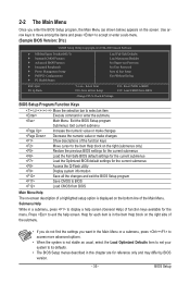
... Saving ESC: Quit F8: Q-Flash Select Item F10: Save & Exit Setup Change CPU's Clock & Voltage F11: Save CMOS to BIOS F12: Load CMOS from BIOS Main Menu Help The on-screen description of a highlighted setup option is not stable as shown below) appears on the screen. 2-2 ...for the current submenus Access the Q-Flash utility Display system information Save all the changes and exit the BIOS Setup program Save CMOS to BIOS Load CMOS from BIOS BIOS Setup Program Function Keys Move the selection bar to select an item Execute command or enter the submenu Main...
... Saving ESC: Quit F8: Q-Flash Select Item F10: Save & Exit Setup Change CPU's Clock & Voltage F11: Save CMOS to BIOS F12: Load CMOS from BIOS Main Menu Help The on-screen description of a highlighted setup option is not stable as shown below) appears on the screen. 2-2 ...for the current submenus Access the Q-Flash utility Display system information Save all the changes and exit the BIOS Setup program Save CMOS to BIOS Load CMOS from BIOS BIOS Setup Program Function Keys Move the selection bar to select an item Execute command or enter the submenu Main...
Manual
Page 36
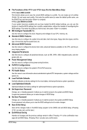
... to configure the system's PCI & PnP resources. PC Health Status Use this function to load the BIOS settings from BIOS If your system becomes unstable and you have loaded the BIOS default settings, you wish to load, then press to complete. MB Intelligent Tweaker(M.I.T.) Use this menu...time and date, hard drive types, floppy disk drive types, and the type of errors that stop the system boot, etc. Advanced BIOS Features Use this menu to configure the device boot order, advanced features available on the CPU, and the primary display adapter. Integrated ...
... to configure the system's PCI & PnP resources. PC Health Status Use this function to load the BIOS settings from BIOS If your system becomes unstable and you have loaded the BIOS default settings, you wish to load, then press to complete. MB Intelligent Tweaker(M.I.T.) Use this menu...time and date, hard drive types, floppy disk drive types, and the type of errors that stop the system boot, etc. Advanced BIOS Features Use this menu to configure the device boot order, advanced features available on the CPU, and the primary display adapter. Integrated ...
Manual
Page 37
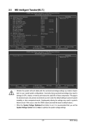
BIOS Setup CPU Host Clock Control x CPU Frequency(MHz) PCIE Clock(MHz) HT Link Width HT Link Frequency Set Memory Clock x Memory Clock } DRAM Configuration ******** System ...
BIOS Setup CPU Host Clock Control x CPU Frequency(MHz) PCIE Clock(MHz) HT Link Width HT Link Frequency Set Memory Clock x Memory Clock } DRAM Configuration ******** System ...
Manual
Page 38
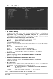
...Help F7: Optimized Defaults EC Firmware Selection Allows you to select the EC firmware version when Advanced Clock Calibration is set to All Cores. BIOS Setup - 38 - Per Core Individually configures Advanced Clock Calibration for the settings to defaults. Value (Core 0), Value (Core 1), Value...Core 2), Value (Core 3) This option is configurable only when Advanced Clock Calibration is set to All Cores. A message which says "BIOS Is Updating EC Firmware!!! All Cores Configures Advanced Clock Calibration for a few seconds and the system will appear. Manual allows the two items...
...Help F7: Optimized Defaults EC Firmware Selection Allows you to select the EC firmware version when Advanced Clock Calibration is set to All Cores. BIOS Setup - 38 - Per Core Individually configures Advanced Clock Calibration for the settings to defaults. Value (Core 0), Value (Core 1), Value...Core 2), Value (Core 3) This option is configurable only when Advanced Clock Calibration is set to All Cores. A message which says "BIOS Is Updating EC Firmware!!! All Cores Configures Advanced Clock Calibration for a few seconds and the system will appear. Manual allows the two items...
Manual
Page 39
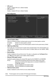
Surround View Enables or disables the Surround View function. troller. Options are: Auto (default), 128MB, 256MB, 512MB. Auto Lets the BIOS automatically determines the primary display port for the onboard graphics controller. BIOS Setup D-SUB/HDMI Sets the D-SUB/HDMI as the graphics display. This option is configurable only if Init Display First...
Surround View Enables or disables the Surround View function. troller. Options are: Auto (default), 128MB, 256MB, 512MB. Auto Lets the BIOS automatically determines the primary display port for the onboard graphics controller. BIOS Setup D-SUB/HDMI Sets the D-SUB/HDMI as the graphics display. This option is configurable only if Init Display First...
Manual
Page 40
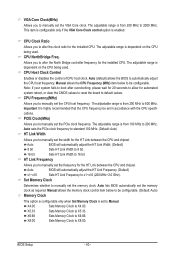
...Host Clock Control Enables or disables the control of CPU host clock. Manual allows the CPU Frequency (MHz) item below to be configurable. Auto BIOS will automatically adjust the HT Link Frequency. (Default) x1~x10 Sets HT Link Frequency to 200 MHz. X4.00 Sets Memory Clock to 16...host frequency. Auto sets the PCIe clock frequency to standard 100 MHz. (Default: Auto) HT Link Width Allows you to Manual. Auto lets BIOS automatically set the memory clock. X8.00 Sets Memory Clock to X5.33. CPU NorthBridge Freq. Manual allows the memory clock control item below ...
...Host Clock Control Enables or disables the control of CPU host clock. Manual allows the CPU Frequency (MHz) item below to be configurable. Auto BIOS will automatically adjust the HT Link Frequency. (Default) x1~x10 Sets HT Link Frequency to 200 MHz. X4.00 Sets Memory Clock to 16...host frequency. Auto sets the PCIe clock frequency to standard 100 MHz. (Default: Auto) HT Link Width Allows you to Manual. Auto lets BIOS automatically set the memory clock. X8.00 Sets Memory Clock to X5.33. CPU NorthBridge Freq. Manual allows the memory clock control item below ...
Manual
Page 41
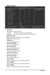
... two single-channel. (Default) DDR3 Timing Items Manual allows all DDR3 Timing items below to single dual-channel. CAS# latency Options are : Auto (default), Manual. BIOS Setup Options are : Auto (default), 4T~12T. Minimum RAS Active Time Options are: Auto (default), 15T~30T. 1T/2T Command Timing Options are : Auto (default...
... two single-channel. (Default) DDR3 Timing Items Manual allows all DDR3 Timing items below to single dual-channel. CAS# latency Options are : Auto (default), Manual. BIOS Setup Options are : Auto (default), 4T~12T. Minimum RAS Active Time Options are: Auto (default), 15T~30T. 1T/2T Command Timing Options are : Auto (default...


