Manual
Page 1
GA-MA78LMT-US2H AM3 socket motherboard for AMD Phenom™ II processor/ AMD Athlon™ II processor User's Manual Rev. 1101 12ME-MA78LMT-1101R
GA-MA78LMT-US2H AM3 socket motherboard for AMD Phenom™ II processor/ AMD Athlon™ II processor User's Manual Rev. 1101 12ME-MA78LMT-1101R
Manual
Page 3
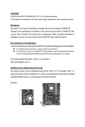
... information on/from the Support&Downloads\Motherboard\Technology Guide page on our website. No part of this manual may be reproduced, copied, translated, transmitted, or published in this product, GIGABYTE provides the following types of GIGABYTE. Example: For example, "REV: 1.0" means the revision of the motherboard is the property of documentations: For...
... information on/from the Support&Downloads\Motherboard\Technology Guide page on our website. No part of this manual may be reproduced, copied, translated, transmitted, or published in this product, GIGABYTE provides the following types of GIGABYTE. Example: For example, "REV: 1.0" means the revision of the motherboard is the property of documentations: For...
Manual
Page 5
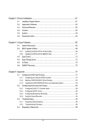
Chapter 3 Drivers Installation 61 3-1 Installing Chipset Drivers 61 3-2 Application Software 62 3-3 Technical Manuals 62 3-4 Contact...63 3-5 System...63 3-6 Download Center 64 Chapter 4 Unique Features 65 4-1 Xpress Recovery2 65 4-2 BIOS Update Utilities 68 4-2-1 Updating the BIOS with the Q-Flash ...
Chapter 3 Drivers Installation 61 3-1 Installing Chipset Drivers 61 3-2 Application Software 62 3-3 Technical Manuals 62 3-4 Contact...63 3-5 System...63 3-6 Download Center 64 Chapter 4 Unique Features 65 4-1 Xpress Recovery2 65 4-2 BIOS Update Utilities 68 4-2-1 Updating the BIOS with the Q-Flash ...
Manual
Page 6
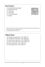
... Out cable (Part No. 12CR1-1SPINO-1*R) COM port cable (Part No. 12CF1-1CM001-3*R) LPT port cable (Part No. 12CF1-1LP001-0*R) - 6 - Box Contents GA-MA78LMT-US2H motherboard Motherboard driver disk User's Manual One IDE cable Two SATA 3Gb/s cables I/O Shield • The box contents above are subject to change without notice. • The motherboard image...
... Out cable (Part No. 12CR1-1SPINO-1*R) COM port cable (Part No. 12CF1-1CM001-3*R) LPT port cable (Part No. 12CF1-1LP001-0*R) - 6 - Box Contents GA-MA78LMT-US2H motherboard Motherboard driver disk User's Manual One IDE cable Two SATA 3Gb/s cables I/O Shield • The box contents above are subject to change without notice. • The motherboard image...
Manual
Page 9
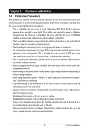
... or connectors. • It is best to wear an electrostatic discharge (ESD) wrist strap when handling electronic com- Prior to installation, carefully read the user's manual and follow these procedures: • Prior to installation, do not allow screws to come in contact with the motherboard circuit or its components. • Make...
... or connectors. • It is best to wear an electrostatic discharge (ESD) wrist strap when handling electronic com- Prior to installation, carefully read the user's manual and follow these procedures: • Prior to installation, do not allow screws to come in contact with the motherboard circuit or its components. • Make...
Manual
Page 15
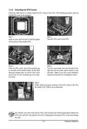
... the steps below to correctly install the CPU cooler on the CPU. (The following procedure uses the GIGABYTE cooler as the picture above shows) to lock into place. (Refer to your CPU cooler installation manual for instructions on installing the cooler.) Step 5: Finally, attach the power connector of the CPU cooler to...
... the steps below to correctly install the CPU cooler on the CPU. (The following procedure uses the GIGABYTE cooler as the picture above shows) to lock into place. (Refer to your CPU cooler installation manual for instructions on installing the cooler.) Step 5: Finally, attach the power connector of the CPU cooler to...
Manual
Page 18
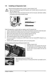
... a Graphics Card: Gently push down on the card are completely inserted into the PCI Express slot. Align the card with your card. Carefully read the manual that supports your expansion card. • Always turn off the computer and unplug the power cord from the power outlet before you begin to the...
... a Graphics Card: Gently push down on the card are completely inserted into the PCI Express slot. Align the card with your card. Carefully read the manual that supports your expansion card. • Always turn off the computer and unplug the power cord from the power outlet before you begin to the...
Manual
Page 31
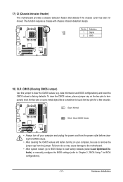
... do so may cause damage to the motherboard. • After system restart, go to BIOS Setup to load factory defaults (select Load Optimized Defaults) or manually configure the BIOS settings (refer to factory defaults. date information and BIOS configurations) and reset the CMOS values to Chapter 2, "BIOS Setup," for a few seconds...
... do so may cause damage to the motherboard. • After system restart, go to BIOS Setup to load factory defaults (select Load Optimized Defaults) or manually configure the BIOS settings (refer to factory defaults. date information and BIOS configurations) and reset the CMOS values to Chapter 2, "BIOS Setup," for a few seconds...
Manual
Page 38
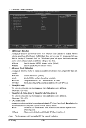
... available depends on the CPU being used). CPU core Control Allows you to determine whether to be configurable. Options are : Auto (default), Manual. Options are : -12%~+12%. Auto Lets the BIOS to All Cores. Advanced Clock Calibration CMOS Setup Utility-Copyright (C) 1984-2009 Award Software... Calibration when using an AMD Black Edition CPU. All Cores Configures Advanced Clock Calibration for a few seconds and the system will appear. Manual Allows you to individually enable/disable CPU Core 2 and Core 3. (Note) This item appears only if you to determine whether to ...
... available depends on the CPU being used). CPU core Control Allows you to determine whether to be configurable. Options are : Auto (default), Manual. Options are : -12%~+12%. Auto Lets the BIOS to All Cores. Advanced Clock Calibration CMOS Setup Utility-Copyright (C) 1984-2009 Award Software... Calibration when using an AMD Black Edition CPU. All Cores Configures Advanced Clock Calibration for a few seconds and the system will appear. Manual Allows you to individually enable/disable CPU Core 2 and Core 3. (Note) This item appears only if you to determine whether to ...
Manual
Page 40
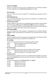
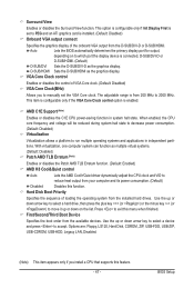
... Frequency Allows you to allow for the installed CPU. Note: If your system fails to boot after overclocking, please wait for 20 seconds to manually set in accordance with the CPU specifications. Auto BIOS will automatically adjust the HT Link Frequency. (Default) x1~x10 Sets HT Link Frequency to... be set the frequency for the HT Link between the CPU and chipset. The adjustable range is enabled. X5.33 Sets Memory Clock to manually set the PCIe clock frequency. This item is configurable only if the VGA Core Clock control option is from 100 MHz to 500 MHz....
... Frequency Allows you to allow for the installed CPU. Note: If your system fails to boot after overclocking, please wait for 20 seconds to manually set in accordance with the CPU specifications. Auto BIOS will automatically adjust the HT Link Frequency. (Default) x1~x10 Sets HT Link Frequency to... be set the frequency for the HT Link between the CPU and chipset. The adjustable range is enabled. X5.33 Sets Memory Clock to manually set the PCIe clock frequency. This item is configurable only if the VGA Core Clock control option is from 100 MHz to 500 MHz....
Manual
Page 41
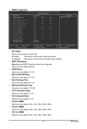
... set memory control mode. CAS# latency Options are : Auto (default), 5T~12T. Unganged Sets memory control mode to two single-channel. (Default) DDR3 Timing Items Manual allows all DDR3 Timing items below to single dual-channel. RAS to CAS R/W Delay Options are : Auto (default), 4T~12T. Options are : Auto (default), 4T... x Trfc2 for DIMM2 x Trfc1 for DIMM3 x Trfc3 for DIMM1 Options are: Auto (default), 90ns, 110ns, 160ns, 300ns, 350ns. TwTr Command Delay Options are : Auto (default), Manual.
... set memory control mode. CAS# latency Options are : Auto (default), 5T~12T. Unganged Sets memory control mode to two single-channel. (Default) DDR3 Timing Items Manual allows all DDR3 Timing items below to single dual-channel. RAS to CAS R/W Delay Options are : Auto (default), 4T~12T. Options are : Auto (default), 4T... x Trfc2 for DIMM2 x Trfc1 for DIMM3 x Trfc3 for DIMM1 Options are: Auto (default), 90ns, 110ns, 160ns, 300ns, 350ns. TwTr Command Delay Options are : Auto (default), Manual.

Manual
Page 42
... +0.750V. Enabled allows the system to simultaneously access different channels of the memory to set memory voltage. Manual allows all voltage control items below to be configurable. (Default: Manual) DDR3 Voltage Control Allows you to +0.3V. Normal Supplies the memory voltage as required. (Default) ...you to +0.3V. Write Recovery Time Options are : Auto (default), 4T~7T. Note: Increasing memory voltage may result in damage to manually set the South Bridge voltage. Normal Supplies the North Bridge voltage as required. Row Cycle Time Options are : Auto (default), 90ns, ...
... +0.750V. Enabled allows the system to simultaneously access different channels of the memory to set memory voltage. Manual allows all voltage control items below to be configurable. (Default: Manual) DDR3 Voltage Control Allows you to +0.3V. Normal Supplies the memory voltage as required. (Default) ...you to +0.3V. Write Recovery Time Options are : Auto (default), 4T~7T. Note: Increasing memory voltage may result in damage to manually set the South Bridge voltage. Normal Supplies the North Bridge voltage as required. Row Cycle Time Options are : Auto (default), 90ns, ...

Manual
Page 45
If you wish to enter the parameters manually, refer to specify whether the installed floppy disk drive is 3-mode floppy disk drive, a Japanese standard floppy disk drive. Capacity Approximate capacity of heads. Floppy 3 ...
If you wish to enter the parameters manually, refer to specify whether the installed floppy disk drive is 3-mode floppy disk drive, a Japanese standard floppy disk drive. Capacity Approximate capacity of heads. Floppy 3 ...
Manual
Page 47
...: Floppy, LS120, Hard Disk, CDROM, ZIP, USB-FDD, USB-ZIP, USB-CDROM, USB-HDD, Legacy LAN, Disabled. (Note) This item appears only if you to manually set to reduce heat output from your computer and its power consumption. (Default) Disabled Disables this menu when finished. With virtualization, one computer system can...
...: Floppy, LS120, Hard Disk, CDROM, ZIP, USB-FDD, USB-ZIP, USB-CDROM, USB-HDD, Legacy LAN, Disabled. (Note) This item appears only if you to manually set to reduce heat output from your computer and its power consumption. (Default) Disabled Disables this menu when finished. With virtualization, one computer system can...
Manual
Page 61
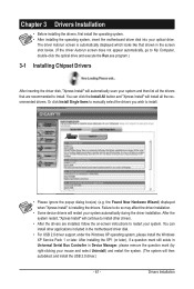
Or click Install Single Items to manually select the drivers you wish to install. Failure to do so may affect the driver installation. • Some device drivers will then autodetect and install ...
Or click Install Single Items to manually select the drivers you wish to install. Failure to do so may affect the driver installation. • Some device drivers will then autodetect and install ...
Manual
Page 62
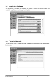
Drivers Installation - 62 - 3-2 Application Software This page displays all the utilities and applications that GIGABYTE develops and some free software. You can click the Install button on the right of an item to install it. 3-3 Technical Manuals This page provides GIGABYTE's application guides, content descriptions for this driver disk, and the motherboard manuals.
Drivers Installation - 62 - 3-2 Application Software This page displays all the utilities and applications that GIGABYTE develops and some free software. You can click the Install button on the right of an item to install it. 3-3 Technical Manuals This page provides GIGABYTE's application guides, content descriptions for this driver disk, and the motherboard manuals.
Manual
Page 68
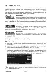
...system safety, users cannot update the backup BIOS manually. Motherboards that matches your motherboard model. 2. site and update the BIOS. Before You Begin 1. However, if the BIOS update file is potentially risky, please do it with the Q-Flash Utility A. GA-MA78LMT-US2H D1c . . . . : BIOS Setup :... XpressRecovery2 : Boot Menu : Qflash 12/02/2009-RS785-SB710-7A66AG0XC-00 Because BIOS flashing is saved to access Q-Flash. For the sake of your floppy disk, USB flash drive, or hard drive. From GIGABYTE's website, download...
...system safety, users cannot update the backup BIOS manually. Motherboards that matches your motherboard model. 2. site and update the BIOS. Before You Begin 1. However, if the BIOS update file is potentially risky, please do it with the Q-Flash Utility A. GA-MA78LMT-US2H D1c . . . . : BIOS Setup :... XpressRecovery2 : Boot Menu : Qflash 12/02/2009-RS785-SB710-7A66AG0XC-00 Because BIOS flashing is saved to access Q-Flash. For the sake of your floppy disk, USB flash drive, or hard drive. From GIGABYTE's website, download...
Manual
Page 71
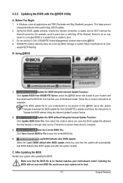
...result in "Update the BIOS without Using the Internet Update Function" below. 2. Follow the on the @BIOS server site, please manually download the BIOS update file from the Internet or through other source. After Updating the BIOS Restart your motherboard model. Update the ...with an incorrect BIOS file could cause your motherboard model. Follow the on-screen instructions to save the BIOS update file obtained from GIGABYTE's website and follow the instructions in a corrupted BIOS or a system that matches your system after the system restarts. Before You ...
...result in "Update the BIOS without Using the Internet Update Function" below. 2. Follow the on the @BIOS server site, please manually download the BIOS update file from the Internet or through other source. After Updating the BIOS Restart your motherboard model. Update the ...with an incorrect BIOS file could cause your motherboard model. Follow the on-screen instructions to save the BIOS update file obtained from GIGABYTE's website and follow the instructions in a corrupted BIOS or a system that matches your system after the system restarts. Before You ...

Manual
Page 80
... Micro Devices, Inc. LD 3 ---- LD No RAID Mode [ Define LD Menu ] Total Drv LD 1 RAID 0 0 Stripe Block: 64 KB Gigabyte Boundary: ON [ Drives Assignments ] Channel:ID Drive Model 1:Mas WDC WD800JD-22LSA0 2:Mas WDC WD800JD-22LSA0 Capabilities SATA 3G SATA 3G Fast Init: ON... key to move to a logical disk set and press to begin the process of manually defining the drive elements and RAID levels for one or multiple disk arrays. LD 8 ---- LD 9 ---- Create Arrays Manually To create a new array, press to enter the Define LD Menu window (Figure...
... Micro Devices, Inc. LD 3 ---- LD No RAID Mode [ Define LD Menu ] Total Drv LD 1 RAID 0 0 Stripe Block: 64 KB Gigabyte Boundary: ON [ Drives Assignments ] Channel:ID Drive Model 1:Mas WDC WD800JD-22LSA0 2:Mas WDC WD800JD-22LSA0 Capabilities SATA 3G SATA 3G Fast Init: ON... key to move to a logical disk set and press to begin the process of manually defining the drive elements and RAID levels for one or multiple disk arrays. LD 8 ---- LD 9 ---- Create Arrays Manually To create a new array, press to enter the Define LD Menu window (Figure...
Manual
Page 88
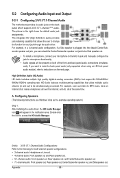
The picture to be simultaneously processed. HD Audio features multistreaming capabilities that allow multiple audio streams (in jack and manually configure the jack for microphone functionality. • Audio signals will appear in a 4-channel audio configuration, if a Side speaker is plugged into the default Center/Sub- ...
The picture to be simultaneously processed. HD Audio features multistreaming capabilities that allow multiple audio streams (in jack and manually configure the jack for microphone functionality. • Audio signals will appear in a 4-channel audio configuration, if a Side speaker is plugged into the default Center/Sub- ...


