
Manual
Page 4
Table of Contents Box Contents...6 Optional Items...6 GA-MA78LM-S2H/GA-MA78LM-S2 Motherboard Layout 7 Block Diagram...8 Chapter 1 Hardware Installation 9 1-1 Installation Precautions 9 1-2 Product Specifications 10 1-3 Installing the CPU and CPU Cooler 13 1-3-1 Installing the CPU 13 1-3-2 Installing the CPU Cooler 15 1-4 Installing the Memory 16 1-4-1 Dual Channel Memory Configuration 16 1-4-2 Installing a Memory 17 1-5 Installing an Expansion Card 18 1-6 Back Panel Connectors 19 1-7 Internal Connectors...
Table of Contents Box Contents...6 Optional Items...6 GA-MA78LM-S2H/GA-MA78LM-S2 Motherboard Layout 7 Block Diagram...8 Chapter 1 Hardware Installation 9 1-1 Installation Precautions 9 1-2 Product Specifications 10 1-3 Installing the CPU and CPU Cooler 13 1-3-1 Installing the CPU 13 1-3-2 Installing the CPU Cooler 15 1-4 Installing the Memory 16 1-4-1 Dual Channel Memory Configuration 16 1-4-2 Installing a Memory 17 1-5 Installing an Expansion Card 18 1-6 Back Panel Connectors 19 1-7 Internal Connectors...
Manual
Page 5
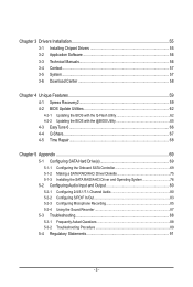
Chapter 3 Drivers Installation 55 3-1 Installing Chipset Drivers 55 3-2 Application Software 56 3-3 Technical Manuals 56 3-4 Contact...57 3-5 System...57 3-6 Download Center 58 Chapter 4 Unique Features 59 4-1 Xpress ...Repair...68 Chapter 5 Appendix...69 5-1 Configuring SATA Hard Drive(s 69 5-1-1 Configuring the Onboard SATA Controller 69 5-1-2 Making a SATA RAID/AHCI Driver Diskette 75 5-1-3 Installing the SATA RAID/AHCI Driver and Operating System 76 5-2 Configuring Audio Input and Output 80 5-2-1 Configuring 2/4/5.1/7.1-Channel Audio 80 5-2-2 Configuring S/PDIF In/Out 83 5-2-3...
Chapter 3 Drivers Installation 55 3-1 Installing Chipset Drivers 55 3-2 Application Software 56 3-3 Technical Manuals 56 3-4 Contact...57 3-5 System...57 3-6 Download Center 58 Chapter 4 Unique Features 59 4-1 Xpress ...Repair...68 Chapter 5 Appendix...69 5-1 Configuring SATA Hard Drive(s 69 5-1-1 Configuring the Onboard SATA Controller 69 5-1-2 Making a SATA RAID/AHCI Driver Diskette 75 5-1-3 Installing the SATA RAID/AHCI Driver and Operating System 76 5-2 Configuring Audio Input and Output 80 5-2-1 Configuring 2/4/5.1/7.1-Channel Audio 80 5-2-2 Configuring S/PDIF In/Out 83 5-2-3...

Manual
Page 9
...you do not have an ESD wrist strap, keep your hands dry and first touch a metal object to eliminate static electricity. • Prior to installing the motherboard, please have a problem related to system components as well as a motherboard, CPU or memory. These stickers are connected tightly and securely.... • When handling the motherboard, avoid touching any installation steps or have it on top of an antistatic pad or within the computer casing. • Do not place the computer system on an...
...you do not have an ESD wrist strap, keep your hands dry and first touch a metal object to eliminate static electricity. • Prior to installing the motherboard, please have a problem related to system components as well as a motherboard, CPU or memory. These stickers are connected tightly and securely.... • When handling the motherboard, avoid touching any installation steps or have it on top of an antistatic pad or within the computer casing. • Do not place the computer system on an...
Manual
Page 10
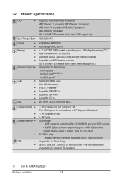
... processors: AMD Phenom™ II processor/ AMD Phenom™ processor/ AMD Athlon™ II processor/ AMD Athlon™ processor/ AMD Sempron™ processor (Go to GIGABYTE's website for the latest CPU support list.) Hyper Transport Bus 5200/2000 MT/s Chipset Memory Onboard Graphics Audio ...) j Only for SATA RAID 0, RAID 1, RAID 10, and JBOD iTE IT8718 chip: - 1 x floppy disk drive connector supporting up to 4 SATA 3Gb/s devices - Support for GA-MA78LM-S2H Hardware Installation - 10 -
... processors: AMD Phenom™ II processor/ AMD Phenom™ processor/ AMD Athlon™ II processor/ AMD Athlon™ processor/ AMD Sempron™ processor (Go to GIGABYTE's website for the latest CPU support list.) Hyper Transport Bus 5200/2000 MT/s Chipset Memory Onboard Graphics Audio ...) j Only for SATA RAID 0, RAID 1, RAID 10, and JBOD iTE IT8718 chip: - 1 x floppy disk drive connector supporting up to 4 SATA 3Gb/s devices - Support for GA-MA78LM-S2H Hardware Installation - 10 -

Manual
Page 11
... CPU fan speed control (Note 5) 2 x 8 Mbit flash Use of licensed AWARD BIOS Support for DualBIOS™ PnP 1.0a, DMI 2.0, SM BIOS 2.4, ACPI 1.0b j Only for GA-MA78LM-S2H - 11 - Hardware Installation
... CPU fan speed control (Note 5) 2 x 8 Mbit flash Use of licensed AWARD BIOS Support for DualBIOS™ PnP 1.0a, DMI 2.0, SM BIOS 2.4, ACPI 1.0b j Only for GA-MA78LM-S2H - 11 - Hardware Installation
Manual
Page 12
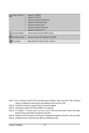
... w w w w Bundled Software w Support for @BIOS Support for Q-Flash Support for Xpress BIOS Rescue Support for Download Center Support for Xpress Install Support for Xpress Recovery2 Support for EasyTune (Note 6) Norton Internet Security (OEM version) Operating System w Support for Microsoft® Windows® ...3cm x 22.0cm (Note 1) Due to Windows Vista/XP 32-bit operating system limitation, when more than 4 GB of physical memory is installed, the actual memory size displayed will be less than 4 GB. (Note 2) The DVI-D port does not support D-Sub connection by adapter....
... w w w w Bundled Software w Support for @BIOS Support for Q-Flash Support for Xpress BIOS Rescue Support for Download Center Support for Xpress Install Support for Xpress Recovery2 Support for EasyTune (Note 6) Norton Internet Security (OEM version) Operating System w Support for Microsoft® Windows® ...3cm x 22.0cm (Note 1) Due to Windows Vista/XP 32-bit operating system limitation, when more than 4 GB of physical memory is installed, the actual memory size displayed will be less than 4 GB. (Note 2) The DVI-D port does not support D-Sub connection by adapter....

Manual
Page 13
... • Do not turn off the computer and unplug the power cord from the power outlet before you begin to install the CPU: • Make sure that the system bus frequency be inserted if oriented incorrectly. (Or you wish to ... of the Socket AM2 Socket A Small Triangle Marking Denotes CPU Pin One AM3/AM2+/AM2 CPU - 13 - Hardware Installation A Small Triangle Mark Denotes Pin One of the CPU may locate the notches on both sides of the CPU and alignment...the CPU cooler is not recommended that the motherboard supports the CPU. (Go to GIGABYTE's website for the peripherals.
... • Do not turn off the computer and unplug the power cord from the power outlet before you begin to install the CPU: • Make sure that the system bus frequency be inserted if oriented incorrectly. (Or you wish to ... of the Socket AM2 Socket A Small Triangle Marking Denotes CPU Pin One AM3/AM2+/AM2 CPU - 13 - Hardware Installation A Small Triangle Mark Denotes Pin One of the CPU may locate the notches on both sides of the CPU and alignment...the CPU cooler is not recommended that the motherboard supports the CPU. (Go to GIGABYTE's website for the peripherals.

Manual
Page 14
... and unplug the power cord from the power outlet to prevent damage to the CPU. • Do not force the CPU into their holes. Hardware Installation - 14 - Step 2: Align the CPU pin one finger down on the CPU socket and gently insert the CPU into the fully locked position. CPU Socket...
... and unplug the power cord from the power outlet to prevent damage to the CPU. • Do not force the CPU into their holes. Hardware Installation - 14 - Step 2: Align the CPU pin one finger down on the CPU socket and gently insert the CPU into the fully locked position. CPU Socket...

Manual
Page 15
... Cooler Follow the steps below to correctly install the CPU cooler on the CPU. (The following procedure uses the GIGABYTE cooler as the picture above shows) to lock into place. (Refer to the mounting lug on one side of the retention frame. Step 4: Turn the ... of the CPU cooler to the CPU fan header (CPU_FAN) on the motherboard. On the other side,push straight down on the retention frame. Hardware Installation Use extreme care when removing the CPU cooler because the thermal grease/tape between the CPU cooler and CPU may damage the CPU. - 15 - Step...
... Cooler Follow the steps below to correctly install the CPU cooler on the CPU. (The following procedure uses the GIGABYTE cooler as the picture above shows) to lock into place. (Refer to the mounting lug on one side of the retention frame. Step 4: Turn the ... of the CPU cooler to the CPU fan header (CPU_FAN) on the motherboard. On the other side,push straight down on the retention frame. Hardware Installation Use extreme care when removing the CPU cooler because the thermal grease/tape between the CPU cooler and CPU may damage the CPU. - 15 - Step...

Manual
Page 16
... memory mode will automatically detect the specifications and capacity of the same capacity, brand, speed, and chips be used . (Go to GIGABYTE's website for the latest memory support list.) • Always turn off the computer and unplug the power cord from the power outlet before...you begin to prevent hardware damage. • Memory modules have a foolproof design. When enabling Dual Channel mode with two memory modules, it is installed. 2. The two DDR2 memory sockets are divided into two channels as following: Channel 0: DDR2_1 Channel 1: DDR2_2 DDR2_1 DDR2_2 Due to CPU limitation...
... memory mode will automatically detect the specifications and capacity of the same capacity, brand, speed, and chips be used . (Go to GIGABYTE's website for the latest memory support list.) • Always turn off the computer and unplug the power cord from the power outlet before...you begin to prevent hardware damage. • Memory modules have a foolproof design. When enabling Dual Channel mode with two memory modules, it is installed. 2. The two DDR2 memory sockets are divided into two channels as following: Channel 0: DDR2_1 Channel 1: DDR2_2 DDR2_1 DDR2_2 Due to CPU limitation...

Manual
Page 17
.... Step 2: The clips at both ends of the memory, push down on the socket. Hardware Installation Place the memory module on the memory and insert it can only fit in one direction. 1-4-2 Installing a Memory Before installing a memory module , make sure to turn off the computer and unplug the power cord from the... power outlet to prevent damage to correctly install your fingers on the top edge of the socket will snap into the memory socket. Step 1: Note the orientation of the memory socket. DDR2 ...
.... Step 2: The clips at both ends of the memory, push down on the socket. Hardware Installation Place the memory module on the memory and insert it can only fit in one direction. 1-4-2 Installing a Memory Before installing a memory module , make sure to turn off the computer and unplug the power cord from the... power outlet to prevent damage to correctly install your fingers on the top edge of the socket will snap into the memory socket. Step 1: Note the orientation of the memory socket. DDR2 ...

Manual
Page 18
...manual that supports your expansion card. • Always turn off the computer and unplug the power cord from the power outlet before you begin to install an expansion card: • Make sure the motherboard supports the expansion card. Locate an expansion slot that came with the slot, and press ...down on the slot and then lift the card straight out from the chassis back panel. 2. Align the card with your card. Install the driver provided with a screw. 5. Remove the metal slot cover from the slot. Make sure the card is fully seated in the expansion slot....
...manual that supports your expansion card. • Always turn off the computer and unplug the power cord from the power outlet before you begin to install an expansion card: • Make sure the motherboard supports the expansion card. Locate an expansion slot that came with the slot, and press ...down on the slot and then lift the card straight out from the chassis back panel. 2. Align the card with your card. Install the driver provided with a screw. 5. Remove the metal slot cover from the slot. Make sure the card is fully seated in the expansion slot....

Manual
Page 19
... but the actual resolutions supported depend on the monitor being used. • After installing the HDMI device, make sure the default device for DVI-D and HDMI is HDCP compliant. j Only for GA-MA78LM-S2H (Note 1) The DVI-D port does not support D-Sub connection by adapter....Set Default. Connect a monitor that supports DVI-D connection to this port. Connect a monitor that supports D-Sub connection to this port. Hardware Installation PS/2 Keyboard/Mouse Port Use this port to transmit the uncompressed audio/video signals and is not supported. - 19 - HDMI Port(Note ...
... but the actual resolutions supported depend on the monitor being used. • After installing the HDMI device, make sure the default device for DVI-D and HDMI is HDCP compliant. j Only for GA-MA78LM-S2H (Note 1) The DVI-D port does not support D-Sub connection by adapter....Set Default. Connect a monitor that supports DVI-D connection to this port. Connect a monitor that supports D-Sub connection to this port. Hardware Installation PS/2 Keyboard/Mouse Port Use this port to transmit the uncompressed audio/video signals and is not supported. - 19 - HDMI Port(Note ...

Manual
Page 20
... data transmission or receiving is occurring Line In Jack (Blue) The default line in jack. Mic In Jack (Pink) The default Mic in jack. Hardware Installation - 20 - Dual Display Combination DVI-D + D-Sub DVI-D + HDMI HDMI + D-Sub Supported or Not Yes No Yes B. Microphones must be used to prevent an electrical short...
... data transmission or receiving is occurring Line In Jack (Blue) The default line in jack. Mic In Jack (Pink) The default Mic in jack. Hardware Installation - 20 - Dual Display Combination DVI-D + D-Sub DVI-D + HDMI HDMI + D-Sub Supported or Not Yes No Yes B. Microphones must be used to prevent an electrical short...

Manual
Page 21
... the power outlet to prevent damage to turn off the devices and your devices are compliant with the connectors you wish to connect. • Before installing the devices, be sure to the devices. • After installing the device and before turning on the motherboard. - 21 - Hardware...
... the power outlet to prevent damage to turn off the devices and your devices are compliant with the connectors you wish to connect. • Before installing the devices, be sure to the devices. • After installing the device and before turning on the motherboard. - 21 - Hardware...

Manual
Page 22
... unstable or unbootable system. • The main power connector is recommended that a power supply that can supply enough stable power to all devices are properly installed. Do not insert the power supply cable into pins under the protective cover when using a 2x12 power supply, remove the protective cover from the main... -12V GND PS_ON (soft On/Off) GND GND GND -5V +5V +5V +5V (Only for 2x12-pin ATX) GND (Only for 2x12-pin ATX) Hardware Installation - 22 -
... unstable or unbootable system. • The main power connector is recommended that a power supply that can supply enough stable power to all devices are properly installed. Do not insert the power supply cable into pins under the protective cover when using a 2x12 power supply, remove the protective cover from the main... -12V GND PS_ON (soft On/Off) GND GND GND -5V +5V +5V +5V (Only for 2x12-pin ATX) GND (Only for 2x12-pin ATX) Hardware Installation - 22 -

Manual
Page 23
... system from overheating. For purchasing the optional floppy disk drive cable, please contact the local dealer. 34 33 2 1 - 23 - Before connecting a floppy disk drive, be installed inside the chassis. 1 CPU_FAN 1 SYS_FAN CPU_FAN: Pin No. 3/4) CPU_FAN/SYS_FAN (Fan Headers) The motherboard has a 4-pin CPU fan header (CPU_FAN) and a 3-pin (SYS_FAN) system fan... connector wire is typically designated by a stripe of the cable is the ground wire). The types of a CPU fan with fan speed control design. Hardware Installation
... system from overheating. For purchasing the optional floppy disk drive cable, please contact the local dealer. 34 33 2 1 - 23 - Before connecting a floppy disk drive, be installed inside the chassis. 1 CPU_FAN 1 SYS_FAN CPU_FAN: Pin No. 3/4) CPU_FAN/SYS_FAN (Fan Headers) The motherboard has a 4-pin CPU fan header (CPU_FAN) and a 3-pin (SYS_FAN) system fan... connector wire is typically designated by a stripe of the cable is the ground wire). The types of a CPU fan with fan speed control design. Hardware Installation

Manual
Page 24
... number. Before attaching the IDE cable, locate the foolproof groove on configur- If more than two hard drives are compatible with SATA 1.5Gb/s standard. Hardware Installation - 24 - The AMD SB710 controller supports RAID 0, RAID 1, RAID 10, and JBOD. If you wish to connect two IDE devices, remember to set the jumpers...
... number. Before attaching the IDE cable, locate the foolproof groove on configur- If more than two hard drives are compatible with SATA 1.5Gb/s standard. Hardware Installation - 24 - The AMD SB710 controller supports RAID 0, RAID 1, RAID 10, and JBOD. If you wish to connect two IDE devices, remember to set the jumpers...

Manual
Page 25
... assignments and the pin assignments are matched correctly. - 25 - The LED keeps blinking when the sys- The system reports system startup status by chassis. Hardware Installation The LED is off when the system is in S3/S4 sleep S3/S4/S5 Off state or powered off your chassis front panel module...
... assignments and the pin assignments are matched correctly. - 25 - The LED keeps blinking when the sys- The system reports system startup status by chassis. Hardware Installation The LED is off when the system is in S3/S4 sleep S3/S4/S5 Off state or powered off your chassis front panel module...

Manual
Page 26
... the wire assignments of the module connector match the pin assignments of a single plug. Definition 10 1 MIC2_L Pin No. Definition 1 CD-L 1 2 GND 3 GND 4 CD-R Hardware Installation - 26 - Pin No. For HD Front Panel Audio: For AC'97 Front Panel Audio: 2 Pin No. If your chassis provides an AC'97 front panel...
... the wire assignments of the module connector match the pin assignments of a single plug. Definition 10 1 MIC2_L Pin No. Definition 1 CD-L 1 2 GND 3 GND 4 CD-R Hardware Installation - 26 - Pin No. For HD Front Panel Audio: For AC'97 Front Panel Audio: 2 Pin No. If your chassis provides an AC'97 front panel...


