Manual
Page 4
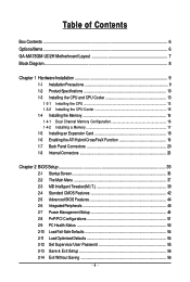
Table of Contents Box Contents ...6 OptionalItems...6 GA-MA78GM-UD2H Motherboard Layout 7 Block Diagram...8 Chapter 1 Hardware Installation 9 1-1 Installation Precautions 9 1-2 Product Specifications 10 1-3 Installing the CPU and CPU Cooler 13 1-3-1 Installing the CPU 13 1-3-2 Installing the CPU Cooler 15 1-4 Installing the Memory 16 1-4-1 Dual Channel Memory Configuration 16 1-4-2 Installing a Memory 17 1-5 Installing an Expansion Card 18 1-6 Enabling the ATI Hybrid...
Table of Contents Box Contents ...6 OptionalItems...6 GA-MA78GM-UD2H Motherboard Layout 7 Block Diagram...8 Chapter 1 Hardware Installation 9 1-1 Installation Precautions 9 1-2 Product Specifications 10 1-3 Installing the CPU and CPU Cooler 13 1-3-1 Installing the CPU 13 1-3-2 Installing the CPU Cooler 15 1-4 Installing the Memory 16 1-4-1 Dual Channel Memory Configuration 16 1-4-2 Installing a Memory 17 1-5 Installing an Expansion Card 18 1-6 Enabling the ATI Hybrid...

Manual
Page 8
... x16 PCI Express Bus x1 PCIe CLK (100 MHz) RTL 8111C RJ45 LAN 1 PCI Express x1 PCI Bus TSB43AB23 2 IEEE 1394a AMD Socket AM2+/AM2 CPU CPU CLK+/-(200 MHz) DDR2 1200 (Note 1)/1066/ 800 MHz DIMM Hyper Transport 3.0 Dual Channel Memory GFX CLK (100 MHz) AMD 780G D-Sub DVI-D or HDMI... Speaker Out Side Speaker Out MIC Line-Out Line-In SPDIF In SPDIF Out (Note 1) Whether 1200 MHz memory speed is supported depends on the CPU being used. (Note 2) Simultaneous output for DVI-D and HDMI is not supported. - 8 -
... x16 PCI Express Bus x1 PCIe CLK (100 MHz) RTL 8111C RJ45 LAN 1 PCI Express x1 PCI Bus TSB43AB23 2 IEEE 1394a AMD Socket AM2+/AM2 CPU CPU CLK+/-(200 MHz) DDR2 1200 (Note 1)/1066/ 800 MHz DIMM Hyper Transport 3.0 Dual Channel Memory GFX CLK (100 MHz) AMD 780G D-Sub DVI-D or HDMI... Speaker Out Side Speaker Out MIC Line-Out Line-In SPDIF In SPDIF Out (Note 1) Whether 1200 MHz memory speed is supported depends on the CPU being used. (Note 2) Simultaneous output for DVI-D and HDMI is not supported. - 8 -
Manual
Page 9
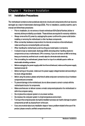
... prevent damage to the motherboard, do not have a problem related to wear an electrostatic discharge (ESD) wrist strap when handling electronic components such as a motherboard, CPU or memory. Prior to installation, carefully read the user's manual and follow these procedures: • Prior to installation, do not remove or break motherboard S/N (Serial...
... prevent damage to the motherboard, do not have a problem related to wear an electrostatic discharge (ESD) wrist strap when handling electronic components such as a motherboard, CPU or memory. Prior to installation, carefully read the user's manual and follow these procedures: • Prior to installation, do not remove or break motherboard S/N (Serial...

Manual
Page 10
... PhenomTM X4 processor/ AMD PhenomTM X3 processor/AMD AthlonTM X2 processor/ AMD AthlonTM processor/AMD SempronTM X2 processor/ AMD SempronTM processor (Go to GIGABYTE's website for the latest CPU support list.) 5200/2000 MT/s North Bridge: AMD 780G South Bridge: AMD SB700 4 x 1.8V DDR2 DIMM sockets supporting up to 16 GB of... internal IEEE 1394a header) Integrated in the South Bridge Up to 12 USB 2.0/1.1 ports (4 on the back panel supporting up to the internal USB headers) GA-MA78GM-UD2H Motherboard - 10 -
... PhenomTM X4 processor/ AMD PhenomTM X3 processor/AMD AthlonTM X2 processor/ AMD AthlonTM processor/AMD SempronTM X2 processor/ AMD SempronTM processor (Go to GIGABYTE's website for the latest CPU support list.) 5200/2000 MT/s North Bridge: AMD 780G South Bridge: AMD SB700 4 x 1.8V DDR2 DIMM sockets supporting up to 16 GB of... internal IEEE 1394a header) Integrated in the South Bridge Up to 12 USB 2.0/1.1 ports (4 on the back panel supporting up to the internal USB headers) GA-MA78GM-UD2H Motherboard - 10 -

Manual
Page 11
...x 4-pin ATX 12V power connector 1 x floppy disk drive connector 1 x IDE connector 5 x SATA 3Gb/s connectors 1 x CPU fan header 1 x system fan header 1 x North Bridge fan header 1 x front panel header 1 x front panel audio header...iTE IT8718 chip Hardware Monitor System voltage detection CPU/System temperature detection CPU/System fan speed detection CPU overheating warning CPU/System fan fail warning CPU/System fan speed control (Note 6) BIOS 2 x ...
...x 4-pin ATX 12V power connector 1 x floppy disk drive connector 1 x IDE connector 5 x SATA 3Gb/s connectors 1 x CPU fan header 1 x system fan header 1 x North Bridge fan header 1 x front panel header 1 x front panel audio header...iTE IT8718 chip Hardware Monitor System voltage detection CPU/System temperature detection CPU/System fan speed detection CPU overheating warning CPU/System fan fail warning CPU/System fan speed control (Note 6) BIOS 2 x ...

Manual
Page 12
GA-MA78GM-UD2H Motherboard - 12 - Unique Features Bundled Software Operating System Form Factor Support for ... memory size displayed will be less than 4 GB. (Note 2) Whether 1200 MHz memory speed is supported depends on the CPU being used. (Note 3) For Windows Vista/XP 32-bit operating system only. (Note 4) The DVI-D port does not... 5) Simultaneous output for DVI-D and HDMI is not supported. (Note 6) Whether the CPU/system fan speed control function is supported will depend on the CPU/ system cooler you install. (Note 7) Available functions in EasyTune may differ by motherboard model...
GA-MA78GM-UD2H Motherboard - 12 - Unique Features Bundled Software Operating System Form Factor Support for ... memory size displayed will be less than 4 GB. (Note 2) Whether 1200 MHz memory speed is supported depends on the CPU being used. (Note 3) For Windows Vista/XP 32-bit operating system only. (Note 4) The DVI-D port does not... 5) Simultaneous output for DVI-D and HDMI is not supported. (Note 6) Whether the CPU/system fan speed control function is supported will depend on the CPU/ system cooler you install. (Note 7) Available functions in EasyTune may differ by motherboard model...

Manual
Page 13
... Mark Denotes Pin One of the CPU may occur. • Set the CPU host frequency in accordance with the CPU specifications. Locate the pin one of the CPU socket and the CPU. Hardware Installation mended that the motherboard supports the CPU. (Go to GIGABYTE's website for the peripherals. 1-3 Installing the CPU and CPU Cooler Read the following guidelines before...
... Mark Denotes Pin One of the CPU may occur. • Set the CPU host frequency in accordance with the CPU specifications. Locate the pin one of the CPU socket and the CPU. Hardware Installation mended that the motherboard supports the CPU. (Go to GIGABYTE's website for the peripherals. 1-3 Installing the CPU and CPU Cooler Read the following guidelines before...

Manual
Page 14
... oriented incorrectly. Follow the steps below to the CPU. Step 2: Align the CPU pin one finger down on the CPU socket and gently insert the CPU into the socket. Do not force the CPU into their holes. GA-MA78GM-UD2H Motherboard - 14 - Adjust the CPU orientation if this occurs. Once the CPU is positioned into its socket, place one (small...
... oriented incorrectly. Follow the steps below to the CPU. Step 2: Align the CPU pin one finger down on the CPU socket and gently insert the CPU into the socket. Do not force the CPU into their holes. GA-MA78GM-UD2H Motherboard - 14 - Adjust the CPU orientation if this occurs. Once the CPU is positioned into its socket, place one (small...

Manual
Page 15
... on the motherboard. Use extreme care when removing the CPU cooler because the thermal grease/tape between the CPU cooler and CPU may damage the CPU. - 15 - 1-3-2 Installing the CPU Cooler Follow the steps below to correctly install the CPU cooler on the CPU. (The following procedure uses the GIGABYTE cooler as the picture above shows) to lock...
... on the motherboard. Use extreme care when removing the CPU cooler because the thermal grease/tape between the CPU cooler and CPU may damage the CPU. - 15 - 1-3-2 Installing the CPU Cooler Follow the steps below to correctly install the CPU cooler on the CPU. (The following procedure uses the GIGABYTE cooler as the picture above shows) to lock...

Manual
Page 16
.... A memory module can be used . (Go to GIGABYTE's website for optimum performance. DDR2_1 DDR2_2 DDR2_3 DDR2_4 Due to CPU limitation, read the following : Channel 0: DDR2_1, DDR2_3 Channel 1: DDR2_2, DDR2_4 Dual Channel Memory Configurations Table DDR2_1 DDR2_2 DDR2_3 DDR2_4 Two Modules DS/SS DS/SS - - - - - - - - GA-MA78GM-UD2H Motherboard - 16 - DS/SS DS/SS Four Modules...
.... A memory module can be used . (Go to GIGABYTE's website for optimum performance. DDR2_1 DDR2_2 DDR2_3 DDR2_4 Due to CPU limitation, read the following : Channel 0: DDR2_1, DDR2_3 Channel 1: DDR2_2, DDR2_4 Dual Channel Memory Configurations Table DDR2_1 DDR2_2 DDR2_3 DDR2_4 Two Modules DS/SS DS/SS - - - - - - - - GA-MA78GM-UD2H Motherboard - 16 - DS/SS DS/SS Four Modules...

Manual
Page 21
.... Use the port to an external audio system that your audio system provides an optical digital audio in connector. Hardware Installation The table below . • CPU: AMD AthlonTM LE1620 or above (Note: Please ensure Hardware Acceleration is compatible with dual channel mode enabled • BIOS Setup: At least 256 MB of...
.... Use the port to an external audio system that your audio system provides an optical digital audio in connector. Hardware Installation The table below . • CPU: AMD AthlonTM LE1620 or above (Note: Please ensure Hardware Acceleration is compatible with dual channel mode enabled • BIOS Setup: At least 256 MB of...

Manual
Page 24
... -12V GND PS_ON(soft On/Off) GND GND GND -5V +5V +5V +5V (Only for 2x12-pinATX) GND (Only for 2x12-pin ATX) GA-MA78GM-UD2H Motherboard - 24 - If a power supply is compatible with power supplies with 2x10 power connectors. Do not insert the power supply cable into pins under the... main power connector is used that can withstand high power consumption be used (500W or greater). The 12V power connector mainly supplies power to the CPU. The power connector possesses a foolproof design. If the 12V power connector is not connected, the computer will not start. • To meet expansion...
... -12V GND PS_ON(soft On/Off) GND GND GND -5V +5V +5V +5V (Only for 2x12-pinATX) GND (Only for 2x12-pin ATX) GA-MA78GM-UD2H Motherboard - 24 - If a power supply is compatible with power supplies with 2x10 power connectors. Do not insert the power supply cable into pins under the... main power connector is used that can withstand high power consumption be used (500W or greater). The 12V power connector mainly supplies power to the CPU. The power connector possesses a foolproof design. If the 12V power connector is not connected, the computer will not start. • To meet expansion...

Manual
Page 25
...voltage. The black connector wire is recommended that a system fan be installed inside the chassis. 3/4) CPU_FAN/SYS_FAN (Fan Headers) The motherboard has a 4-pin CPU fan header (CPU_FAN)and a 4-pin system fan header (SYS_FAN). CPU_FAN: Pin No. Definition 1 GND 1 2 +12V / Speed Control CPU_FAN 3 ...color-coded power connector wires. For optimum heat dissipation, it is the ground wire. The motherboard supports CPU fan speed control, which requires the use of a CPU fan with color-coded power connector wires. Definition 1 1 GND 2 +12V 3 NC • ...
...voltage. The black connector wire is recommended that a system fan be installed inside the chassis. 3/4) CPU_FAN/SYS_FAN (Fan Headers) The motherboard has a 4-pin CPU fan header (CPU_FAN)and a 4-pin system fan header (SYS_FAN). CPU_FAN: Pin No. Definition 1 GND 1 2 +12V / Speed Control CPU_FAN 3 ...color-coded power connector wires. For optimum heat dissipation, it is the ground wire. The motherboard supports CPU fan speed control, which requires the use of a CPU fan with color-coded power connector wires. Definition 1 1 GND 2 +12V 3 NC • ...

Manual
Page 37
... for the menu. BIOS Setup Press to its defaults. • The BIOS Setup menus described in a submenu, press to BIOS Load CMOS from BIOS Change CPU's Clock & Voltage BIOS Setup Program Function Keys Move the selection bar to select an item Execute command or enter the submenu Main Menu: Exit the...
... for the menu. BIOS Setup Press to its defaults. • The BIOS Setup menus described in a submenu, press to BIOS Load CMOS from BIOS Change CPU's Clock & Voltage BIOS Setup Program Function Keys Move the selection bar to select an item Execute command or enter the submenu Main Menu: Exit the...

Manual
Page 38
.... PnP/PCI Configurations Use this menu to configure the system's PCI & PnP resources. PC Health Status Use this task.) GA-MA78GM-UD2H Motherboard - 38 - A supervisor password allows you to restrict access to the system and BIOS Setup. You can also carry out this menu to...stop the system boot, etc. Advanced BIOS Features Use this menu to configure the device boot order, advanced features available on the CPU, and the primary display adapter. Integrated Peripherals Use this menu to configure all peripheral devices, such as IDE, SATA, USB, integrated...
.... PnP/PCI Configurations Use this menu to configure the system's PCI & PnP resources. PC Health Status Use this task.) GA-MA78GM-UD2H Motherboard - 38 - A supervisor password allows you to restrict access to the system and BIOS Setup. You can also carry out this menu to...stop the system boot, etc. Advanced BIOS Features Use this menu to configure the device boot order, advanced features available on the CPU, and the primary display adapter. Integrated Peripherals Use this menu to configure all peripheral devices, such as IDE, SATA, USB, integrated...
Manual
Page 39
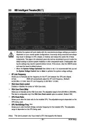
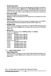
...Award Software MB Intelligent Tweaker(M.I.T.) HT Link Frequency VGA Core Clock control x VGA Core Clock (Mhz) CPU Clock Ratio CPU NorthBridge Freq. (Note) CPU Host Clock Control x CPU Frequency (MHz) PCIE Clock (MHz) Set Memory Clock x Memory Clock ******** System Voltage Optimized System Voltage... Control x DDR2 Voltage Control x NorthBridge Volt Control x SouthBridge Volt Control x CPU NB VID Control (Note) x CPU Voltage Control Normal CPU Vcore ******** [Auto] [Disabled] 500 [Auto] [Auto] [Auto] 200 [Auto] [Auto] DDR 800 [Auto] ...
...Award Software MB Intelligent Tweaker(M.I.T.) HT Link Frequency VGA Core Clock control x VGA Core Clock (Mhz) CPU Clock Ratio CPU NorthBridge Freq. (Note) CPU Host Clock Control x CPU Frequency (MHz) PCIE Clock (MHz) Set Memory Clock x Memory Clock ******** System Voltage Optimized System Voltage... Control x DDR2 Voltage Control x NorthBridge Volt Control x SouthBridge Volt Control x CPU NB VID Control (Note) x CPU Voltage Control Normal CPU Vcore ******** [Auto] [Disabled] 500 [Auto] [Auto] [Auto] 200 [Auto] [Auto] DDR 800 [Auto] ...
Manual
Page 40
... highly recommended that supports this feature. DDR 800 Sets Memory Clock to X2.66. GA-MA78GM-UD2H Motherboard - 40 - Manual allows the CPU Frequency (Mhz) item below to be set the PCIe clock frequency. CPU Frequency (MHz) Allows you use a AM2+ CPU: X2.00 Sets Memory Clock to manually set the memory clock as required. When...
... highly recommended that supports this feature. DDR 800 Sets Memory Clock to X2.66. GA-MA78GM-UD2H Motherboard - 40 - Manual allows the CPU Frequency (Mhz) item below to be set the PCIe clock frequency. CPU Frequency (MHz) Allows you use a AM2+ CPU: X2.00 Sets Memory Clock to manually set the memory clock as required. When...

Manual
Page 41
...Bridge voltage as required. (Default) +0.1V ~ +0.3V Increases South Bridge voltage by 0.1V to 0.3V at 0.1V increment. Normal sets the CPU Northbridge VID voltage as required. (Default) +0.1V ~ +0.3V Increases memory voltage by 0.1V to 0.3V at 0.1V increment. Normal sets the... VID voltage. Normal Supplies the memory voltage as required. (Default: Normal) Note: Increasing CPU voltage may result in damage to your CPU or reduce the useful life of the CPU. CPU Voltage Control Allows you to set memory voltage. Normal Supplies the North Bridge voltage as required. BIOS ...
...Bridge voltage as required. (Default) +0.1V ~ +0.3V Increases South Bridge voltage by 0.1V to 0.3V at 0.1V increment. Normal sets the CPU Northbridge VID voltage as required. (Default) +0.1V ~ +0.3V Increases memory voltage by 0.1V to 0.3V at 0.1V increment. Normal sets the... VID voltage. Normal Supplies the memory voltage as required. (Default: Normal) Note: Increasing CPU voltage may result in damage to your CPU or reduce the useful life of the CPU. CPU Voltage Control Allows you to set memory voltage. Normal Supplies the North Bridge voltage as required. BIOS ...

Manual
Page 44
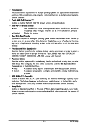
..., or the onboard VGA. Init Display First Specifies the first initiation of system memory allocated solely for display. Enables or disables the Surround View function. GA-MA78GM-UD2H Motherboard - 44 - Capability Away Mode [UMA] [Auto] Disabled [D-SUB/DVI] [PCI Slot] [Disabled] [Enabled] [Auto] [Press Enter] [Floppy] [Hard Disk] [CDROM] [Setup] [Disabled] [... +/-/PU/PD: Value F10: Save F6: Fail-Safe Defaults ESC: Exit F1: General Help F7: Optimized Defaults Internal Graphics Mode Allows you install a CPU that supports this memory for the onboard graphics controller.
..., or the onboard VGA. Init Display First Specifies the first initiation of system memory allocated solely for display. Enables or disables the Surround View function. GA-MA78GM-UD2H Motherboard - 44 - Capability Away Mode [UMA] [Auto] Disabled [D-SUB/DVI] [PCI Slot] [Disabled] [Enabled] [Auto] [Press Enter] [Floppy] [Hard Disk] [CDROM] [Setup] [Disabled] [... +/-/PU/PD: Value F10: Save F6: Fail-Safe Defaults ESC: Exit F1: General Help F7: Optimized Defaults Internal Graphics Mode Allows you install a CPU that supports this memory for the onboard graphics controller.
Manual
Page 45
... or disables the Patch AMD TLB Erratum function. (Default: Enabled) AMD K8 Cool&Quiet control Auto Lets the AMD Cool'n'Quiet driver dynamically adjust the CPU clock and VID to accept. After configuring this item, set the password(s) under the Set Supervisor/User Password item in independent partitions. HDD S.M.A.R.T. Away Mode...
... or disables the Patch AMD TLB Erratum function. (Default: Enabled) AMD K8 Cool&Quiet control Auto Lets the AMD Cool'n'Quiet driver dynamically adjust the CPU clock and VID to accept. After configuring this item, set the password(s) under the Set Supervisor/User Password item in independent partitions. HDD S.M.A.R.T. Away Mode...


