Manual
Page 7
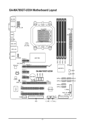
GA-MA785GT-UD3H Motherboard Layout KB_USB VGA_DVI ATX_12V_2X4 HDMI OPTICAL USB_1394 USB_LAN CPU_FAN Socket AM3 PWR_FAN ATX AUDIO F_AUDIO PCIEX1_1 AMD 785G IT8718 F_USB1 F_USB2 F_USB3 DDR3_1 DDR3_2 DDR3_3 DDR3_4 SYS_FAN2 RTL8111C PCIEX16_1 IDE CD_IN PCIEX1_2 PCIEX1_3 CODEC PCIEX4_1 SPDIF_IO PCI1 PCI2 COM GA-MA785GT-UD3H AMD SB710 BATTERY CLR_CMOS SATA2_1 SATA2_0 B_BIOS M_BIOS SATA2_5 SATA2_4 TSB43AB23 SATA2_3 SATA2_2 F_PANEL PWR_LED CI LPT SYS_FAN1 FDD F_1394_1 F_1394_2 - 7 -
GA-MA785GT-UD3H Motherboard Layout KB_USB VGA_DVI ATX_12V_2X4 HDMI OPTICAL USB_1394 USB_LAN CPU_FAN Socket AM3 PWR_FAN ATX AUDIO F_AUDIO PCIEX1_1 AMD 785G IT8718 F_USB1 F_USB2 F_USB3 DDR3_1 DDR3_2 DDR3_3 DDR3_4 SYS_FAN2 RTL8111C PCIEX16_1 IDE CD_IN PCIEX1_2 PCIEX1_3 CODEC PCIEX4_1 SPDIF_IO PCI1 PCI2 COM GA-MA785GT-UD3H AMD SB710 BATTERY CLR_CMOS SATA2_1 SATA2_0 B_BIOS M_BIOS SATA2_5 SATA2_4 TSB43AB23 SATA2_3 SATA2_2 F_PANEL PWR_LED CI LPT SYS_FAN1 FDD F_1394_1 F_1394_2 - 7 -
Manual
Page 12
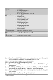
...Time Repair Support for Q-Share Norton Internet Security (OEM version) Operating System w Support for Microsoft® Windows® Vista/XP Form Factor w ATX Form Factor; 30.5cm x 22.9cm (Note 1) Due to install it in the PCIEX16_1 slot for DVI-D and HDMI is supported will ...system cooler you are installing a PCI Express graphics card, be less than 4 GB. (Note 2) The DVI-D port does not support D-Sub connection by motherboard model. mum performance. (Note 5) The PCIEX1_2 and PCIEX1_3 slots share bandwidth with a x4 card, the PCIEX1_2 and PCIEX1_3 slots become unavailable. (Note 6)...
...Time Repair Support for Q-Share Norton Internet Security (OEM version) Operating System w Support for Microsoft® Windows® Vista/XP Form Factor w ATX Form Factor; 30.5cm x 22.9cm (Note 1) Due to install it in the PCIEX16_1 slot for DVI-D and HDMI is supported will ...system cooler you are installing a PCI Express graphics card, be less than 4 GB. (Note 2) The DVI-D port does not support D-Sub connection by motherboard model. mum performance. (Note 5) The PCIEX1_2 and PCIEX1_3 slots share bandwidth with a x4 card, the PCIEX1_2 and PCIEX1_3 slots become unavailable. (Note 6)...

Manual
Page 23
... the device cable has been securely attached to turn off the devices and your computer. 1-8 Internal Connectors 1 3 5 2 12 4 15 13 10 14 20 18 1) ATX_12V_2X4 2) ATX 3) CPU_FAN 4) SYS_FAN1/SYS_FAN2 5) PWR_FAN 6) FDD 7) IDE 8) SATA2_0/1/2/3/4/5 9) PWR_LED 10) BATTERY 7 8 11 9 4 6 16 19 17 11) F_PANEL 12) F_AUDIO 13) CD_IN 14) SPDIF_IO 15) F_USB1/F_USB2..., make sure your devices are compliant with the connectors you wish to connect. • Before installing the devices, be sure to the connector on the motherboard. - 23 -
... the device cable has been securely attached to turn off the devices and your computer. 1-8 Internal Connectors 1 3 5 2 12 4 15 13 10 14 20 18 1) ATX_12V_2X4 2) ATX 3) CPU_FAN 4) SYS_FAN1/SYS_FAN2 5) PWR_FAN 6) FDD 7) IDE 8) SATA2_0/1/2/3/4/5 9) PWR_LED 10) BATTERY 7 8 11 9 4 6 16 19 17 11) F_PANEL 12) F_AUDIO 13) CD_IN 14) SPDIF_IO 15) F_USB1/F_USB2..., make sure your devices are compliant with the connectors you wish to connect. • Before installing the devices, be sure to the connector on the motherboard. - 23 -

Manual
Page 24
... power connector is not connected, the computer will not start. • To meet expansion requirements, it is turned off and all the components on the motherboard. When using a power supply providing a 2x2 12V and a 2x10 power connector. 1 5 4 8 ATX_12V_2X4 ATX_12V_2X4: Pin No. Before connecting the power connector, first...(Only for 2x4-pin 12V) 3 GND 4 GND 5 +12V (Only for 2x4-pin 12V) 6 +12V (Only for 2x4-pin 12V) 7 +12V 8 +12V 12 24 1 13 ATX ATX: Pin No. 1 2 3 4 5 6 7 8 9 10 11 12 Definition Pin No. 3.3V 13 3.3V 14 GND 15 +5V 16 GND 17 +5V 18 GND 19 Power ...
... power connector is not connected, the computer will not start. • To meet expansion requirements, it is turned off and all the components on the motherboard. When using a power supply providing a 2x2 12V and a 2x10 power connector. 1 5 4 8 ATX_12V_2X4 ATX_12V_2X4: Pin No. Before connecting the power connector, first...(Only for 2x4-pin 12V) 3 GND 4 GND 5 +12V (Only for 2x4-pin 12V) 6 +12V (Only for 2x4-pin 12V) 7 +12V 8 +12V 12 24 1 13 ATX ATX: Pin No. 1 2 3 4 5 6 7 8 9 10 11 12 Definition Pin No. 3.3V 13 3.3V 14 GND 15 +5V 16 GND 17 +5V 18 GND 19 Power ...

Manual
Page 97
Is the power connector of the CPU cooler connected to the motherboard. The problem is verified and solved. No Correctly insert the memory into the memory socket. Yes The problem is verified and solved. Connect the ATX main power cable and the 12V power cable. START Turn off the power. ...Yes Isolate the short circuit. Appendix Make sure the motherboard does not short-circuit with the chassis or other metal objects. No Check ...
Is the power connector of the CPU cooler connected to the motherboard. The problem is verified and solved. No Correctly insert the memory into the memory socket. Yes The problem is verified and solved. Connect the ATX main power cable and the 12V power cable. START Turn off the power. ...Yes Isolate the short circuit. Appendix Make sure the motherboard does not short-circuit with the chassis or other metal objects. No Check ...


