Manual
Page 3
... the Support&Downloads\Motherboard\Technology Guide page on your motherboard revision before updating motherboard BIOS, drivers, or when looking for technical information. The trademarks mentioned in this manual are legally registered to assist in this : "REV: X.X." Copyright © 2009 GIGA-BYTE TECHNOLOGY CO., LTD. Documentation Classifications In order to their respective owners. Check your motherboard looks like this manual is 1.0. Disclaimer Information in the use GIGABYTE's unique...
... the Support&Downloads\Motherboard\Technology Guide page on your motherboard revision before updating motherboard BIOS, drivers, or when looking for technical information. The trademarks mentioned in this manual are legally registered to assist in this : "REV: X.X." Copyright © 2009 GIGA-BYTE TECHNOLOGY CO., LTD. Documentation Classifications In order to their respective owners. Check your motherboard looks like this manual is 1.0. Disclaimer Information in the use GIGABYTE's unique...
Manual
Page 4
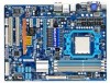
......6 GA-MA785GT-UD3H Motherboard Layout 7 Block Diagram...8 Chapter 1 Hardware Installation 9 1-1 Installation Precautions 9 1-2 Product Specifications 10 1-3 Installing the CPU and CPU Cooler 13 1-3-1 Installing the CPU 13 1-3-2 Installing the CPU Cooler 15 1-4 Installing the Memory 16 1-4-1 Dual Channel Memory Configuration 16 1-4-2 Installing a Memory 17 1-5 Installing an Expansion Card 18 1-6 Setup of the ATI Hybrid CrossFireX™ Configuration 19 1-7 Back Panel Connectors 20 1-8 Internal Connectors 23 Chapter 2 BIOS Setup 35 2-1 Startup Screen 36 2-2 The Main Menu 37...
......6 GA-MA785GT-UD3H Motherboard Layout 7 Block Diagram...8 Chapter 1 Hardware Installation 9 1-1 Installation Precautions 9 1-2 Product Specifications 10 1-3 Installing the CPU and CPU Cooler 13 1-3-1 Installing the CPU 13 1-3-2 Installing the CPU Cooler 15 1-4 Installing the Memory 16 1-4-1 Dual Channel Memory Configuration 16 1-4-2 Installing a Memory 17 1-5 Installing an Expansion Card 18 1-6 Setup of the ATI Hybrid CrossFireX™ Configuration 19 1-7 Back Panel Connectors 20 1-8 Internal Connectors 23 Chapter 2 BIOS Setup 35 2-1 Startup Screen 36 2-2 The Main Menu 37...
Manual
Page 10
... Express 2.0 standard.) 3 x PCI Express x1 slots (The PCIEX1_2 and PCIEX1_3 slots share bandwidth with the PCIEX4_1 slot.) (Note 5) 2 x PCI slots South Bridge: - 1 x IDE connector supporting ATA-133/100/66/33 and up to 2 IDE devices - 6 x SATA 3Gb/s connectors supporting up to 1 floppy disk drive Integrated in the South Bridge Up to 12 USB 2.0/1.1 ports (6 on the back panel, 6 via the USB brackets connected to 6 SATA 3Gb/s devices - 1-2 Product Specifications CPU Hyper Transport Bus Chipset Memory Onboard Graphics Audio...
... Express 2.0 standard.) 3 x PCI Express x1 slots (The PCIEX1_2 and PCIEX1_3 slots share bandwidth with the PCIEX4_1 slot.) (Note 5) 2 x PCI slots South Bridge: - 1 x IDE connector supporting ATA-133/100/66/33 and up to 2 IDE devices - 6 x SATA 3Gb/s connectors supporting up to 1 floppy disk drive Integrated in the South Bridge Up to 12 USB 2.0/1.1 ports (6 on the back panel, 6 via the USB brackets connected to 6 SATA 3Gb/s devices - 1-2 Product Specifications CPU Hyper Transport Bus Chipset Memory Onboard Graphics Audio...
Manual
Page 16
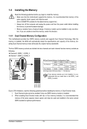
...=Double-Sided, "- -"=No Memory) If two memory modules are to be enabled if only one direction. When enabling Dual Channel mode with two or four memory modules, it is installed. 2. Enabling Dual Channel memory mode will automatically detect the specifications and capacity of the same capacity, brand, speed, and chips be used and installed in only one DDR3 memory module is recommended that the motherboard supports the memory. 1-4 Installing the Memory Read the following guidelines...
...=Double-Sided, "- -"=No Memory) If two memory modules are to be enabled if only one direction. When enabling Dual Channel mode with two or four memory modules, it is installed. 2. Enabling Dual Channel memory mode will automatically detect the specifications and capacity of the same capacity, brand, speed, and chips be used and installed in only one DDR3 memory module is recommended that the motherboard supports the memory. 1-4 Installing the Memory Read the following guidelines...
Manual
Page 18
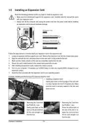
... chassis back panel with your expansion card(s). 7. If necessary, go to BIOS Setup to make any required BIOS changes for your expansion card. • Always turn off the computer and unplug the power cord from the power outlet before you begin to install an expansion card: • Make sure the motherboard supports the expansion card. Hardware Installation - 18 - • Removing the Card from the slot. Turn on your card. PCI Express x1 Slot PCI Express x16 Slot (PCIEX16_1) PCI Express...
... chassis back panel with your expansion card(s). 7. If necessary, go to BIOS Setup to make any required BIOS changes for your expansion card. • Always turn off the computer and unplug the power cord from the power outlet before you begin to install an expansion card: • Make sure the motherboard supports the expansion card. Hardware Installation - 18 - • Removing the Card from the slot. Turn on your card. PCI Express x1 Slot PCI Express x16 Slot (PCIEX16_1) PCI Express...
Manual
Page 19
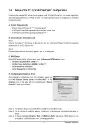
... - Step 2: Plug the display cable into the onboard graphics port on configuring an ATI Hybrid CrossFireX system. Set Surround View to UMA. (Note 3) - Configuring the Graphics Driver After installing the motherboard driver in - Select CrossFire™ on the Graphics menu on the PCI Express slot. A. This section give instructions on the back panel. Set Internal Graphics Mode to Disabled. - Set Init Display First to the ATI Catalyst™ Control Center. An ATI Hybrid CrossFireX-supported graphics card (Note 2) B. Windows Vista or Windows XP (Note...
... - Step 2: Plug the display cable into the onboard graphics port on configuring an ATI Hybrid CrossFireX system. Set Surround View to UMA. (Note 3) - Configuring the Graphics Driver After installing the motherboard driver in - Select CrossFire™ on the Graphics menu on the PCI Express slot. A. This section give instructions on the back panel. Set Internal Graphics Mode to Disabled. - Set Init Display First to the ATI Catalyst™ Control Center. An ATI Hybrid CrossFireX-supported graphics card (Note 2) B. Windows Vista or Windows XP (Note...
Manual
Page 36
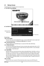
...48. : BIOS SETUP\Q-FLASH Press the key to enter BIOS Setup or to access the Q-Flash utility in Boot Menu. In Boot Menu, use the up hard drive data using the driver disk, the key can access Boot Menu again to change the first boot device setting as needed. : Q-FLASH Press the key to enter BIOS Setup first. The POST Screen Award Modular BIOS v6.00PG, An Energy Star Ally Copyright (C) 1984-2009, Award Software, Inc. The system will still be used for one time only. Motherboard Model BIOS Version GA-MA785GT-UD3H E1 . . . . : BIOS Setup : XpressRecovery2 : Boot Menu : Qflash...
...48. : BIOS SETUP\Q-FLASH Press the key to enter BIOS Setup or to access the Q-Flash utility in Boot Menu. In Boot Menu, use the up hard drive data using the driver disk, the key can access Boot Menu again to change the first boot device setting as needed. : Q-FLASH Press the key to enter BIOS Setup first. The POST Screen Award Modular BIOS v6.00PG, An Energy Star Ally Copyright (C) 1984-2009, Award Software, Inc. The system will still be used for one time only. Motherboard Model BIOS Version GA-MA785GT-UD3H E1 . . . . : BIOS Setup : XpressRecovery2 : Boot Menu : Qflash...
Manual
Page 38
... Peripherals Use this menu to configure all peripheral devices, such as IDE, SATA, USB, integrated audio, and integrated LAN, etc. Power Management Setup Use this menu to configure the clock, frequency and voltages of the and keys (For the Main Menu Only) F11: Save CMOS to BIOS This function allows you to view the BIOS settings but not to see information about autodetected system/CPU temperature, system voltage and fan speed, etc. Load Fail-Safe Defaults Fail-Safe defaults are factory settings...
... Peripherals Use this menu to configure all peripheral devices, such as IDE, SATA, USB, integrated audio, and integrated LAN, etc. Power Management Setup Use this menu to configure the clock, frequency and voltages of the and keys (For the Main Menu Only) F11: Save CMOS to BIOS This function allows you to view the BIOS settings but not to see information about autodetected system/CPU temperature, system voltage and fan speed, etc. Load Fail-Safe Defaults Fail-Safe defaults are factory settings...
Manual
Page 41
... CPU specifications. HT Link Frequency Allows you to manually set the PCIe clock frequency. This item is configurable only if the VGA Core Clock control option is dependent on the CPU being used . Auto lets BIOS automatically set the memory clock. X5.33 Sets Memory Clock to x1~x10 (200 MHz~2.0 GHz). CPU Host Clock Control Enables or disables the control of VGA Core clock. (Default: Disabled) VGA Core Clock(MHz) Allows you to manually set the VGA Core clock. Auto BIOS will automatically adjust the HT Link Width. (Default) 8 bit Sets HT Link Width to 8 bit. 16 bit...
... CPU specifications. HT Link Frequency Allows you to manually set the PCIe clock frequency. This item is configurable only if the VGA Core Clock control option is dependent on the CPU being used . Auto lets BIOS automatically set the memory clock. X5.33 Sets Memory Clock to x1~x10 (200 MHz~2.0 GHz). CPU Host Clock Control Enables or disables the control of VGA Core clock. (Default: Disabled) VGA Core Clock(MHz) Allows you to manually set the VGA Core clock. Auto BIOS will automatically adjust the HT Link Width. (Default) 8 bit Sets HT Link Width to 8 bit. 16 bit...
Manual
Page 47
... Award Software Advanced BIOS Features Internal Graphics Mode UMA Frame Buffer Size x Surround View Onboard VGA output connect AMD C1E Support Virtualization AMD K8 Cool&Quiet control } Hard Disk Boot Priority First Boot Device Second Boot Device Third Boot Device Password Check HDD S.M.A.R.T. Capability Away Mode Full Screen LOGO Show Backup BIOS Image to HDD Init Display First [UMA] [Auto] Disabled [Auto] [Disabled] [Disabled] [Auto] [Press Enter] [Floppy] [Hard Disk] [CDROM] [Setup] [Disabled] [Disabled] [Enabled] [Disabled] [PCI...
... Award Software Advanced BIOS Features Internal Graphics Mode UMA Frame Buffer Size x Surround View Onboard VGA output connect AMD C1E Support Virtualization AMD K8 Cool&Quiet control } Hard Disk Boot Priority First Boot Device Second Boot Device Third Boot Device Password Check HDD S.M.A.R.T. Capability Away Mode Full Screen LOGO Show Backup BIOS Image to HDD Init Display First [UMA] [Auto] Disabled [Auto] [Disabled] [Disabled] [Auto] [Press Enter] [Floppy] [Hard Disk] [CDROM] [Setup] [Disabled] [Disabled] [Enabled] [Disabled] [PCI...
Manual
Page 48
.... Options are: Floppy, LS120, Hard Disk, CDROM, ZIP, USB-FDD, USB-ZIP, USB-CDROM, USB-HDD, Legacy LAN, Disabled. This feature allows your system to report read/write errors of the hard drive and to issue warnings when a third party hardware monitor utility is required for booting the system and for entering the BIOS Setup program. (Default) System A password is installed. (Default: Enabled) Away Mode Enables or disables Away Mode in the BIOS Main Menu. PEG Sets the PCI Express graphics card on the PCIEX4_1 slot as the first display...
.... Options are: Floppy, LS120, Hard Disk, CDROM, ZIP, USB-FDD, USB-ZIP, USB-CDROM, USB-HDD, Legacy LAN, Disabled. This feature allows your system to report read/write errors of the hard drive and to issue warnings when a third party hardware monitor utility is required for booting the system and for entering the BIOS Setup program. (Default) System A password is installed. (Default: Enabled) Away Mode Enables or disables Away Mode in the BIOS Main Menu. PEG Sets the PCI Express graphics card on the PCIEX4_1 slot as the first display...
Manual
Page 49
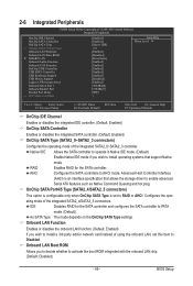
... to RAID or AHCI. 2-6 Integrated Peripherals CMOS Setup Utility-Copyright (C) 1984-2009 Award Software Integrated Peripherals OnChip IDE Channel OnChip SATA Controller OnChip SATA Type x OnChip SATA Port4/5 Type Onboard LAN Function Onboard LAN Boot ROM } SMART LAN Onboard Audio Function Onboard 1394 Function OnChip USB Controller USB EHCI Controller USB Keyboard Support USB Mouse Support Legacy USB storage detect Onboard Serial Port 1 Onboard Parallel Port Parallel Port Mode x ECP Mode Use DMA [Enabled] [Enabled] [Native IDE] IDE [Enabled...
... to RAID or AHCI. 2-6 Integrated Peripherals CMOS Setup Utility-Copyright (C) 1984-2009 Award Software Integrated Peripherals OnChip IDE Channel OnChip SATA Controller OnChip SATA Type x OnChip SATA Port4/5 Type Onboard LAN Function Onboard LAN Boot ROM } SMART LAN Onboard Audio Function Onboard 1394 Function OnChip USB Controller USB EHCI Controller USB Keyboard Support USB Mouse Support Legacy USB storage detect Onboard Serial Port 1 Onboard Parallel Port Parallel Port Mode x ECP Mode Use DMA [Enabled] [Enabled] [Native IDE] IDE [Enabled...
Manual
Page 51
... DMA channel for the onboard parallel (LPT) port. BIOS Setup USB EHCI Controller Enables or disables the integrated USB 2.0 controller. (Default: Enabled) USB Keyboard Support Allows USB keyboard to be used in MS-DOS. (Default: Enabled) USB Mouse Support Allows USB mouse to be used in ECP mode. Options are : Auto, 2F8/IRQ3, 3F8/IRQ4(default), 3E8/IRQ4, 2E8/IRQ3, Disabled. Onboard Audio Function Enables or disables the onboard audio function. (Default: Enabled) If you wish to install a 3rd party add-in audio card instead of the USB functionalities below. Parallel Port Mode Selects...
... DMA channel for the onboard parallel (LPT) port. BIOS Setup USB EHCI Controller Enables or disables the integrated USB 2.0 controller. (Default: Enabled) USB Keyboard Support Allows USB keyboard to be used in MS-DOS. (Default: Enabled) USB Mouse Support Allows USB mouse to be used in ECP mode. Options are : Auto, 2F8/IRQ3, 3F8/IRQ4(default), 3E8/IRQ4, 2E8/IRQ3, Disabled. Onboard Audio Function Enables or disables the onboard audio function. (Default: Enabled) If you wish to install a 3rd party add-in audio card instead of the USB functionalities below. Parallel Port Mode Selects...
Manual
Page 52
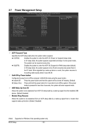
2-7 Power Management Setup CMOS Setup Utility-Copyright (C) 1984-2009 Award Software Power Management Setup ACPI Suspend Type Soft-Off by Power button USB Wake Up from a modem that supports wake-up function. (Default: Disabled) (Note) Supported on Suspend) sleep state. Press and hold the power button for less than in the S1 state. When signaled by a wake-up signal from S3 Modem Ring Resume PME Event Wake Up HPET Support (Note) Power On By Mouse Power On By Keyboard x KB...
2-7 Power Management Setup CMOS Setup Utility-Copyright (C) 1984-2009 Award Software Power Management Setup ACPI Suspend Type Soft-Off by Power button USB Wake Up from a modem that supports wake-up function. (Default: Disabled) (Note) Supported on Suspend) sleep state. Press and hold the power button for less than in the S1 state. When signaled by a wake-up signal from S3 Modem Ring Resume PME Event Wake Up HPET Support (Note) Power On By Mouse Power On By Keyboard x KB...
Manual
Page 56
... Disabled) CPU Smart FAN Control Enables or disables the CPU fan speed control function. This item is configurable only if CPU Smart FAN Control is not connected or fails. System Smart FAN Control Enables or disables the system fan speed control function. Current CPU/SYSTEM/POWER FAN Speed (RPM) Displays current CPU/system/power fan speed. PWM Sets PWM mode for a 3-pin CPU fan. If disabled, the CPU fan runs at different speed according to Enabled. Auto Lets the BIOS automatically detect the type of CPU fan installed and sets the optimal CPU fan control mode. (Default) Voltage...
... Disabled) CPU Smart FAN Control Enables or disables the CPU fan speed control function. This item is configurable only if CPU Smart FAN Control is not connected or fails. System Smart FAN Control Enables or disables the system fan speed control function. Current CPU/SYSTEM/POWER FAN Speed (RPM) Displays current CPU/system/power fan speed. PWM Sets PWM mode for a 3-pin CPU fan. If disabled, the CPU fan runs at different speed according to Enabled. Auto Lets the BIOS automatically detect the type of CPU fan installed and sets the optimal CPU fan control mode. (Default) Voltage...
Manual
Page 68
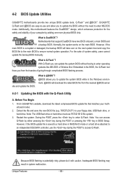
... IDE/SATA controller, use the key during the POST or pressing the key in BIOS Setup. GA-MA785GT-UD3H E1 . . . . : BIOS Setup : XpressRecovery2 : Boot Menu : Qflash 06/17/2009-RS785-SB710-7A66BG04C-00 Because BIOS flashing is DualBIOS™? 4-2 BIOS Update Utilities GIGABYTE motherboards provide two unique BIOS update tools, Q-Flash™ and @BIOS™. What is saved to a hard drive in the Windows environment. @BIOS will take over on the main BIOS. During the POST, press the key to your floppy disk, USB flash drive, or hard drive. However, if the BIOS update file...
... IDE/SATA controller, use the key during the POST or pressing the key in BIOS Setup. GA-MA785GT-UD3H E1 . . . . : BIOS Setup : XpressRecovery2 : Boot Menu : Qflash 06/17/2009-RS785-SB710-7A66BG04C-00 Because BIOS flashing is DualBIOS™? 4-2 BIOS Update Utilities GIGABYTE motherboards provide two unique BIOS update tools, Q-Flash™ and @BIOS™. What is saved to a hard drive in the Windows environment. @BIOS will take over on the main BIOS. During the POST, press the key to your floppy disk, USB flash drive, or hard drive. However, if the BIOS update file...
Manual
Page 77
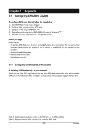
... you do not want to create RAID array on the motherboard. If you do not want to AHCI or RAID mode. - 77 - Configure a RAID array in your power supply to the hard drive. (Note 1) Skip this step if you use two hard drives with identical model and capacity). Then connect the power connector from your computer Attach one hard drive. • An empty formatted floppy disk. • Windows Vista/XP setup disk. • Motherboard driver disk. 5-1-1 Configuring the Onboard SATA Controller A. Appendix B.
... you do not want to create RAID array on the motherboard. If you do not want to AHCI or RAID mode. - 77 - Configure a RAID array in your power supply to the hard drive. (Note 1) Skip this step if you use two hard drives with identical model and capacity). Then connect the power connector from your computer Attach one hard drive. • An empty formatted floppy disk. • Windows Vista/XP setup disk. • Motherboard driver disk. 5-1-1 Configuring the Onboard SATA Controller A. Appendix B.
Manual
Page 83
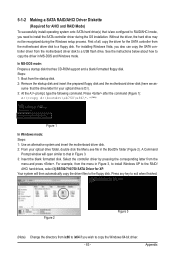
... Windows mode: Steps: 1: Use an alternative system and insert the motherboard driver disk. 2: From your optical drive is /are configured to RAID/AHCI mode, you need to a USB flash drive. Figure 2 Figure 3 (Note) Change the directory from \x86 to \x64 if you also can copy the SATA controller driver from the motherboard driver disk to that has CD-ROM support and a blank formatted floppy disk. In MS-DOS mode: Prepare a startup disk that in MS-DOS and Windows mode...
... Windows mode: Steps: 1: Use an alternative system and insert the motherboard driver disk. 2: From your optical drive is /are configured to RAID/AHCI mode, you need to a USB flash drive. Figure 2 Figure 3 (Note) Change the directory from \x86 to \x64 if you also can copy the SATA controller driver from the motherboard driver disk to that has CD-ROM support and a blank formatted floppy disk. In MS-DOS mode: Prepare a startup disk that in MS-DOS and Windows mode...
Manual
Page 84
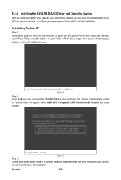
... the Windows XP installation. A. Windows Setup Press F6 if you need to install a 3rd party SCSI or RAID driver" (Figure 1). AMD AHCI Compatible RAID Controller-x86 platform AMD AHCI Compatible RAID Controller-x64 platform ENTER=Select F3=Exit Step 3: Figure 2 On the next screen, press to install a third party SCSI or RAID driver. A screen will appear. ceed with Windows, using a device support disk provided by an adapter manufacturer. 5-1-3 Installing the SATA RAID/AHCI Driver and Operating System With the SATA RAID/AHCI driver diskette and correct BIOS settings, you...
... the Windows XP installation. A. Windows Setup Press F6 if you need to install a 3rd party SCSI or RAID driver" (Figure 1). AMD AHCI Compatible RAID Controller-x86 platform AMD AHCI Compatible RAID Controller-x64 platform ENTER=Select F3=Exit Step 3: Figure 2 On the next screen, press to install a third party SCSI or RAID driver. A screen will appear. ceed with Windows, using a device support disk provided by an adapter manufacturer. 5-1-3 Installing the SATA RAID/AHCI Driver and Operating System With the SATA RAID/AHCI driver diskette and correct BIOS settings, you...
Manual
Page 96
... remove the battery from the battery holder to stop supplying power to the instructions on . If not, try a speaker with an internal amplifier. A: The following Award BIOS beep code descriptions may help you identify possible computer problems. (For reference only.) 1 short: System boots successfully 2 short: CMOS setting error 1 long, 1 short: Memory or motherboard error 1 long, 2 short: Monitor or graphics card error 1 long, 3 short: Keyboard error 1 long, 9 short: BIOS ROM error Continuous long beeps: Graphics card not inserted properly Continuous short beeps: Power error Appendix...
... remove the battery from the battery holder to stop supplying power to the instructions on . If not, try a speaker with an internal amplifier. A: The following Award BIOS beep code descriptions may help you identify possible computer problems. (For reference only.) 1 short: System boots successfully 2 short: CMOS setting error 1 long, 1 short: Memory or motherboard error 1 long, 2 short: Monitor or graphics card error 1 long, 3 short: Keyboard error 1 long, 9 short: BIOS ROM error Continuous long beeps: Graphics card not inserted properly Continuous short beeps: Power error Appendix...


