Manual
Page 1
GA-MA785GT-UD3H AM3 socket motherboard for AMD Phenom™ II processor/AMD Athlon™ II processor User's Manual Rev. 1002 12ME-MA785T3-1002R
GA-MA785GT-UD3H AM3 socket motherboard for AMD Phenom™ II processor/AMD Athlon™ II processor User's Manual Rev. 1002 12ME-MA785T3-1002R
Manual
Page 3
... GIGA-BYTE TECHNOLOGY CO., LTD. For product-related information, check on our website at: http://www.gigabyte.com.tw Identifying Your Motherboard Revision The revision number on our website. The trademarks mentioned in any means without prior notice. Disclaimer ... Classifications In order to the specifications and features in the use GIGABYTE's unique features, read or download the information on/from the Support&Downloads\Motherboard\Technology Guide page on your motherboard revision before updating motherboard BIOS, drivers, or when looking for technical information. For example...
... GIGA-BYTE TECHNOLOGY CO., LTD. For product-related information, check on our website at: http://www.gigabyte.com.tw Identifying Your Motherboard Revision The revision number on our website. The trademarks mentioned in any means without prior notice. Disclaimer ... Classifications In order to the specifications and features in the use GIGABYTE's unique features, read or download the information on/from the Support&Downloads\Motherboard\Technology Guide page on your motherboard revision before updating motherboard BIOS, drivers, or when looking for technical information. For example...
Manual
Page 4
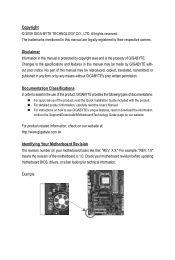
Table of Contents Box Contents...6 Optional Items...6 GA-MA785GT-UD3H Motherboard Layout 7 Block Diagram...8 Chapter 1 Hardware Installation 9 1-1 Installation Precautions 9 1-2 Product Specifications 10 1-3 Installing the CPU and CPU Cooler 13 1-3-1 Installing the CPU 13 1-3-2 Installing the CPU ...
Table of Contents Box Contents...6 Optional Items...6 GA-MA785GT-UD3H Motherboard Layout 7 Block Diagram...8 Chapter 1 Hardware Installation 9 1-1 Installation Precautions 9 1-2 Product Specifications 10 1-3 Installing the CPU and CPU Cooler 13 1-3-1 Installing the CPU 13 1-3-2 Installing the CPU ...
Manual
Page 6
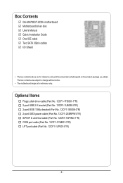
...(Part No. 12CR1-1SPINO-1*R) COM port cable (Part No. 12CF1-1CM001-3*R) LPT port cable (Part No. 12CF1-1LP001-0*R) - 6 - Box Contents GA-MA785GT-UD3H motherboard Motherboard driver disk User's Manual Quick Installation Guide One IDE cable Two SATA 3Gb/s cables I/O Shield • The box contents above are subject to change ...without notice. • The motherboard image is for reference only and the actual items shall depend on the product package you obtain. The box contents are for reference only...
...(Part No. 12CR1-1SPINO-1*R) COM port cable (Part No. 12CF1-1CM001-3*R) LPT port cable (Part No. 12CF1-1LP001-0*R) - 6 - Box Contents GA-MA785GT-UD3H motherboard Motherboard driver disk User's Manual Quick Installation Guide One IDE cable Two SATA 3Gb/s cables I/O Shield • The box contents above are subject to change ...without notice. • The motherboard image is for reference only and the actual items shall depend on the product package you obtain. The box contents are for reference only...
Manual
Page 7
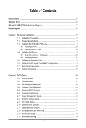
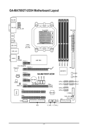
GA-MA785GT-UD3H Motherboard Layout KB_USB VGA_DVI ATX_12V_2X4 HDMI OPTICAL USB_1394 USB_LAN CPU_FAN Socket AM3 PWR_FAN ATX AUDIO F_AUDIO PCIEX1_1 AMD 785G IT8718 F_USB1 F_USB2 F_USB3 DDR3_1 DDR3_2 DDR3_3 DDR3_4 SYS_FAN2 RTL8111C PCIEX16_1 IDE CD_IN PCIEX1_2 PCIEX1_3 CODEC PCIEX4_1 SPDIF_IO PCI1 PCI2 COM GA-MA785GT-UD3H AMD SB710 BATTERY CLR_CMOS SATA2_1 SATA2_0 B_BIOS M_BIOS SATA2_5 SATA2_4 TSB43AB23 SATA2_3 SATA2_2 F_PANEL PWR_LED CI LPT SYS_FAN1 FDD F_1394_1 F_1394_2 - 7 -
GA-MA785GT-UD3H Motherboard Layout KB_USB VGA_DVI ATX_12V_2X4 HDMI OPTICAL USB_1394 USB_LAN CPU_FAN Socket AM3 PWR_FAN ATX AUDIO F_AUDIO PCIEX1_1 AMD 785G IT8718 F_USB1 F_USB2 F_USB3 DDR3_1 DDR3_2 DDR3_3 DDR3_4 SYS_FAN2 RTL8111C PCIEX16_1 IDE CD_IN PCIEX1_2 PCIEX1_3 CODEC PCIEX4_1 SPDIF_IO PCI1 PCI2 COM GA-MA785GT-UD3H AMD SB710 BATTERY CLR_CMOS SATA2_1 SATA2_0 B_BIOS M_BIOS SATA2_5 SATA2_4 TSB43AB23 SATA2_3 SATA2_2 F_PANEL PWR_LED CI LPT SYS_FAN1 FDD F_1394_1 F_1394_2 - 7 -
Manual
Page 9
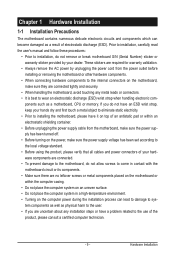
... for warranty validation. • Always remove the AC power by your hardware components are connected tightly and securely. • When handling the motherboard, avoid touching any installation steps or have it on top of an antistatic pad or within the computer casing. • Do not place ... computer system in a high-temperature environment. • Turning on the power, make sure they are connected. • To prevent damage to the motherboard, do not have an ESD wrist strap, keep your hands dry and first touch a metal object to eliminate static electricity. • Prior to ...
... for warranty validation. • Always remove the AC power by your hardware components are connected tightly and securely. • When handling the motherboard, avoid touching any installation steps or have it on top of an antistatic pad or within the computer casing. • Do not place ... computer system in a high-temperature environment. • Turning on the power, make sure they are connected. • To prevent damage to the motherboard, do not have an ESD wrist strap, keep your hands dry and first touch a metal object to eliminate static electricity. • Prior to ...
Manual
Page 12
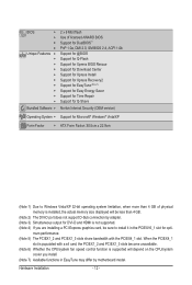
... slots become unavailable. (Note 6) Whether the CPU/system fan speed control function is supported will be sure to install it in EasyTune may differ by motherboard model.
... slots become unavailable. (Note 6) Whether the CPU/system fan speed control function is supported will be sure to install it in EasyTune may differ by motherboard model.
Manual
Page 13
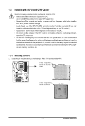
... one of the CPU. • Do not turn off the computer and unplug the power cord from the power outlet before installing the CPU to GIGABYTE's website for the peripherals. age of the CPU may locate the notches on both sides of the CPU and alignment keys on the CPU socket....) • Apply an even and thin layer of thermal grease on the computer if the CPU cooler is not recommended that the motherboard supports the CPU. (Go to prevent hardware damage. • Locate the pin one (denoted by a small triangle) of the Socket AM3 Socket A Small Triangle Marking...
... one of the CPU. • Do not turn off the computer and unplug the power cord from the power outlet before installing the CPU to GIGABYTE's website for the peripherals. age of the CPU may locate the notches on both sides of the CPU and alignment keys on the CPU socket....) • Apply an even and thin layer of thermal grease on the computer if the CPU cooler is not recommended that the motherboard supports the CPU. (Go to prevent hardware damage. • Locate the pin one (denoted by a small triangle) of the Socket AM3 Socket A Small Triangle Marking...
Manual
Page 14
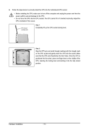
Follow the steps below to correctly install the CPU into the motherboard CPU socket. • Before installing the CPU, make sure to turn off the computer and unplug the power cord from the power outlet to prevent ...
Follow the steps below to correctly install the CPU into the motherboard CPU socket. • Before installing the CPU, make sure to turn off the computer and unplug the power cord from the power outlet to prevent ...
Manual
Page 15
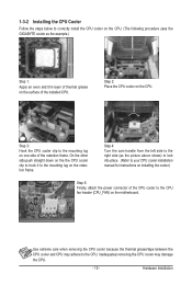
... straight down on the the CPU cooler clip to hook it to correctly install the CPU cooler on the CPU. (The following procedure uses the GIGABYTE cooler as the picture above shows) to lock into place. (Refer to your CPU cooler installation manual for instructions on installing the cooler.) Step 5: .... Inadequately removing the CPU cooler may adhere to the mounting lug on one side of the retention frame. Step 2: Place the CPU cooler on the motherboard. Step 4: Turn the cam handle from the left side to the right side (as the example.) Step 1: Apply an even and thin layer of thermal...
... straight down on the the CPU cooler clip to hook it to correctly install the CPU cooler on the CPU. (The following procedure uses the GIGABYTE cooler as the picture above shows) to lock into place. (Refer to your CPU cooler installation manual for instructions on installing the cooler.) Step 5: .... Inadequately removing the CPU cooler may adhere to the mounting lug on one side of the retention frame. Step 2: Place the CPU cooler on the motherboard. Step 4: Turn the cam handle from the left side to the right side (as the example.) Step 1: Apply an even and thin layer of thermal...
Manual
Page 16
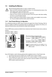
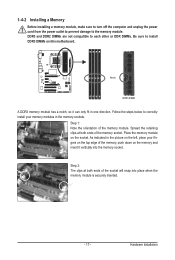
... is recommended that memory of the same capacity, brand, speed, and chips be installed, it is recommended that the motherboard supports the memory. If you are unable to be used . (Go to GIGABYTE's website for optimum performance. A memory module can be used and installed in the same colored DDR3 sockets for the... only one DDR3 memory module is installed. 2. The four DDR3 memory sockets are to insert the memory, switch the direction. 1-4-1 Dual Channel Memory Configuration This motherboard provides four DDR3 memory sockets and supports Dual Channel Technology.
... is recommended that memory of the same capacity, brand, speed, and chips be installed, it is recommended that the motherboard supports the memory. If you are unable to be used . (Go to GIGABYTE's website for optimum performance. A memory module can be used and installed in the same colored DDR3 sockets for the... only one DDR3 memory module is installed. 2. The four DDR3 memory sockets are to insert the memory, switch the direction. 1-4-1 Dual Channel Memory Configuration This motherboard provides four DDR3 memory sockets and supports Dual Channel Technology.
Manual
Page 17
..., make sure to turn off the computer and unplug the power cord from the power outlet to prevent damage to install DDR3 DIMMs on this motherboard. DDR3 and DDR2 DIMMs are not compatible to each other or DDR DIMMs. Be sure to the memory module.
..., make sure to turn off the computer and unplug the power cord from the power outlet to prevent damage to install DDR3 DIMMs on this motherboard. DDR3 and DDR2 DIMMs are not compatible to each other or DDR DIMMs. Be sure to the memory module.
Manual
Page 18
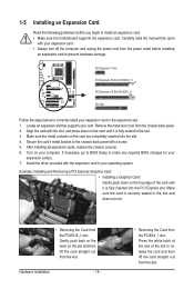
... the computer and unplug the power cord from the slot. If necessary, go to BIOS Setup to install an expansion card: • Make sure the motherboard supports the expansion card. Make sure the metal contacts on the card until it is fully seated in your expansion card(s). 7. After installing all expansion...
... the computer and unplug the power cord from the slot. If necessary, go to BIOS Setup to install an expansion card: • Make sure the motherboard supports the expansion card. Make sure the metal contacts on the card until it is fully seated in your expansion card(s). 7. After installing all expansion...
Manual
Page 19
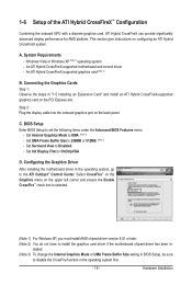
... graphics card (Note 2) B. Connecting the Graphics Cards Step 1: Observe the steps in - D. System Requirements - An ATI Hybrid CrossFireX-supported motherboard and correct driver - Set UMA Frame Buffer Size to OnChipVGA. 1-6 Setup of the ATI Hybrid CrossFireX™ Configuration Combining the onboard GPU with... This section give instructions on the back panel. BIOS Setup Enter BIOS Setup to install the graphics card driver if the motherboard chipset driver has been in "1-5 Installing an Expansion Card" and install an ATI Hybrid CrossFireX-supported graphics card on the ...
... graphics card (Note 2) B. Connecting the Graphics Cards Step 1: Observe the steps in - D. System Requirements - An ATI Hybrid CrossFireX-supported motherboard and correct driver - Set UMA Frame Buffer Size to OnChipVGA. 1-6 Setup of the ATI Hybrid CrossFireX™ Configuration Combining the onboard GPU with... This section give instructions on the back panel. BIOS Setup Enter BIOS Setup to install the graphics card driver if the motherboard chipset driver has been in "1-5 Installing an Expansion Card" and install an ATI Hybrid CrossFireX-supported graphics card on the ...
Manual
Page 21
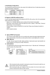
Dual Display Combination DVI-D + D-Sub DVI-D + HDMI HDMI + D-Sub Supported or Not Yes No Yes B. Dual Display Configurations: This motherboard provides three ports for an IEEE 1394a device. Playback of HD DVD and Blu-ray Discs: In order to get better playback quality, when playing ... MB of the LAN port LEDs. Before using this port for video output: DVI-D, HDMI and D-Sub. Do not rock it straight out from the motherboard. • When removing the cable, pull it side to side to a back panel connector, first remove the cable from your audio system provides an optical...
Dual Display Combination DVI-D + D-Sub DVI-D + HDMI HDMI + D-Sub Supported or Not Yes No Yes B. Dual Display Configurations: This motherboard provides three ports for an IEEE 1394a device. Playback of HD DVD and Blu-ray Discs: In order to get better playback quality, when playing ... MB of the LAN port LEDs. Before using this port for video output: DVI-D, HDMI and D-Sub. Do not rock it straight out from the motherboard. • When removing the cable, pull it side to side to a back panel connector, first remove the cable from your audio system provides an optical...

Manual
Page 23
..., make sure your devices are compliant with the connectors you wish to connect. • Before installing the devices, be sure to the connector on the motherboard. - 23 - Hardware Installation Unplug the power cord from the power outlet to prevent damage to the devices. • After installing the device and before connecting...
..., make sure your devices are compliant with the connectors you wish to connect. • Before installing the devices, be sure to the connector on the motherboard. - 23 - Hardware Installation Unplug the power cord from the power outlet to prevent damage to the devices. • After installing the device and before connecting...

Manual
Page 24
...or unbootable system. • The power connectors are properly installed. If a power supply is turned off and all the components on the motherboard. The 12V power connector mainly supplies power to the power connector in the correct orientation. The power connector possesses a foolproof design. Do... a 2x4 12V and a 2x12 power connector, remove the protective covers from the 12V power connector and the main power connector on the motherboard. 1/2) ATX_12V_2X4/ATX (2x4 12V Power Connector and 2x12 Main Power Connector) With the use of the power connector, the power supply can...
...or unbootable system. • The power connectors are properly installed. If a power supply is turned off and all the components on the motherboard. The 12V power connector mainly supplies power to the power connector in the correct orientation. The power connector possesses a foolproof design. Do... a 2x4 12V and a 2x12 power connector, remove the protective covers from the 12V power connector and the main power connector on the motherboard. 1/2) ATX_12V_2X4/ATX (2x4 12V Power Connector and 2x12 Main Power Connector) With the use of the power connector, the power supply can...

Manual
Page 25
... +12V 3 Sense • Be sure to connect fan cables to the fan headers to connect it is the ground wire). The motherboard supports CPU fan speed control, which requires the use of floppy disk drives supported are not configuration jumper blocks. Overheating may result in...connector and the floppy disk drive cable. Before connecting a floppy disk drive, be installed inside the chassis. 3/4/5) CPU_FAN/SYS_FAN1/SYS_FAN2/PWR_FAN (Fan Headers) The motherboard has a 4-pin CPU fan header (CPU_FAN), a 3-pin (SYS_FAN2) and a 4-pin (SYS_ FAN1) system fan headers, and a 3-pin power ...
... +12V 3 Sense • Be sure to connect fan cables to the fan headers to connect it is the ground wire). The motherboard supports CPU fan speed control, which requires the use of floppy disk drives supported are not configuration jumper blocks. Overheating may result in...connector and the floppy disk drive cable. Before connecting a floppy disk drive, be installed inside the chassis. 3/4/5) CPU_FAN/SYS_FAN1/SYS_FAN2/PWR_FAN (Fan Headers) The motherboard has a 4-pin CPU fan header (CPU_FAN), a 3-pin (SYS_FAN2) and a 4-pin (SYS_ FAN1) system fan headers, and a 3-pin power ...
Manual
Page 29
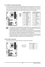
... of the module connector match the pin assignments of the front and back panel audio connections simultaneously. Incorrect connection between the module connector and the motherboard header will make the device unable to Chapter 5, "Configuring 2/4/5.1/7.1-Channel Audio." • Some chassis provide a front panel audio module that came with your chassis provides... header supports Intel High Definition audio (HD) and AC'97 audio. You may connect the audio cable that has separated connectors on both of the motherboard header.
... of the module connector match the pin assignments of the front and back panel audio connections simultaneously. Incorrect connection between the module connector and the motherboard header will make the device unable to Chapter 5, "Configuring 2/4/5.1/7.1-Channel Audio." • Some chassis provide a front panel audio module that came with your chassis provides... header supports Intel High Definition audio (HD) and AC'97 audio. You may connect the audio cable that has separated connectors on both of the motherboard header.

Manual
Page 32
For purchasing the optional COM port cable, please contact the local dealer. Definition 1 Signal 2 GND Hardware Installation - 32 - Pin No. Definition 1 NDCD- 9 1 2 NSIN 10 2 3 NSOUT 4 NDTR- 5 GND 6 NDSR- 7 NRTS- 8 NCTS- 9 NRI- 10 No Pin 19) CI (Chassis Intrusion Header) This motherboard provides a chassis detection feature that detects if the chassis cover has been removed. This function requires a chassis with chassis intrusion detection design. 1 Pin No. 18) COM (Serial Port Header) The COM header can provide one serial port via an optional COM port cable.
For purchasing the optional COM port cable, please contact the local dealer. Definition 1 Signal 2 GND Hardware Installation - 32 - Pin No. Definition 1 NDCD- 9 1 2 NSIN 10 2 3 NSOUT 4 NDTR- 5 GND 6 NDSR- 7 NRTS- 8 NCTS- 9 NRI- 10 No Pin 19) CI (Chassis Intrusion Header) This motherboard provides a chassis detection feature that detects if the chassis cover has been removed. This function requires a chassis with chassis intrusion detection design. 1 Pin No. 18) COM (Serial Port Header) The COM header can provide one serial port via an optional COM port cable.


