
Manual
Page 8
Block Diagram PCIe CLK (100 MHz) AM3 CPU CPU CLK+/- (200 MHz) DDR3 1666 (O.C.)/1333/1066 MHz 1 PCI Express x16 Dual Channel Memory Hyper Transport 3.0 PCI Express x16 PCI Express Bus ... RJ45 LAN Dual BIOS PCI Bus TSB43AB23 2 IEEE 1394a AMD 785G GFX CLK (100 MHz) D-Sub DVI-D or HDMI (Note) DDR3 SidePort Memoryj 12 USB Ports AMD SB710 ATA-133/100/66/33 IDE Channel 6 SATA 3Gb/s CODEC LPC Bus IT8718 Floppy LPT Port... MIC Line Out Line In S/PDIF In S/ PDIF Out 2 PCI PCI CLK (33 MHz) j Only for GA-MA785GPMT-UD2H. (Note) Simultaneous output for DVI-D and HDMI is not supported. - 8 -
Block Diagram PCIe CLK (100 MHz) AM3 CPU CPU CLK+/- (200 MHz) DDR3 1666 (O.C.)/1333/1066 MHz 1 PCI Express x16 Dual Channel Memory Hyper Transport 3.0 PCI Express x16 PCI Express Bus ... RJ45 LAN Dual BIOS PCI Bus TSB43AB23 2 IEEE 1394a AMD 785G GFX CLK (100 MHz) D-Sub DVI-D or HDMI (Note) DDR3 SidePort Memoryj 12 USB Ports AMD SB710 ATA-133/100/66/33 IDE Channel 6 SATA 3Gb/s CODEC LPC Bus IT8718 Floppy LPT Port... MIC Line Out Line In S/PDIF In S/ PDIF Out 2 PCI PCI CLK (33 MHz) j Only for GA-MA785GPMT-UD2H. (Note) Simultaneous output for DVI-D and HDMI is not supported. - 8 -
Manual
Page 10
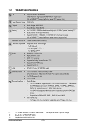
Only for GA-MA785GMT-UD2H. Only for GA-MA785GPMT-UD2H. Hardware Installation - 10 - 1-2 Product Specifications CPU Support for AM3 processors: AMD Phenom™ II processor/ AMD Athlon™ II processor (Go to GIGABYTE's website for the latest CPU support list.)... 1) Dual channel memory architecture Support for DDR3 1666 (O.C.)/1333/1066 MHz memory modules (Go to GIGABYTE's website for the latest memory support list.) Intergrated Memory 128MB DDR3 SidePort memory Onboard Graphics Audio ...
Only for GA-MA785GMT-UD2H. Only for GA-MA785GPMT-UD2H. Hardware Installation - 10 - 1-2 Product Specifications CPU Support for AM3 processors: AMD Phenom™ II processor/ AMD Athlon™ II processor (Go to GIGABYTE's website for the latest CPU support list.)... 1) Dual channel memory architecture Support for DDR3 1666 (O.C.)/1333/1066 MHz memory modules (Go to GIGABYTE's website for the latest memory support list.) Intergrated Memory 128MB DDR3 SidePort memory Onboard Graphics Audio ...
Manual
Page 16
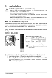
...No Memory) If two memory modules are unable to insert the memory, switch the direction. 1-4-1 Dual Channel Memory Configuration This motherboard provides four DDR3 memory sockets and supports Dual Channel Technology. DDR3_1 DDR3_2 DDR3_3 DDR3_4 Due to CPU limitations, read the following : Channel 0: DDR3_1, DDR3_3 Channel ...; Always turn off the computer and unplug the power cord from the power outlet before you are to be used . (Go to GIGABYTE's website for optimum performance. If you begin to prevent hardware damage. • Memory modules have a foolproof design. When enabling Dual ...
...No Memory) If two memory modules are unable to insert the memory, switch the direction. 1-4-1 Dual Channel Memory Configuration This motherboard provides four DDR3 memory sockets and supports Dual Channel Technology. DDR3_1 DDR3_2 DDR3_3 DDR3_4 Due to CPU limitations, read the following : Channel 0: DDR3_1, DDR3_3 Channel ...; Always turn off the computer and unplug the power cord from the power outlet before you are to be used . (Go to GIGABYTE's website for optimum performance. If you begin to prevent hardware damage. • Memory modules have a foolproof design. When enabling Dual ...
Manual
Page 17
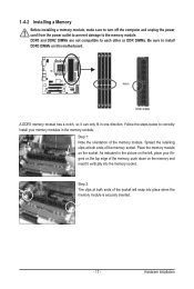
... DDR2 DIMMs are not compatible to each other or DDR DIMMs. Be sure to the memory module. Notch DDR3 DIMM A DDR3 memory module has a notch, so it vertically into place when the memory module is securely inserted. - 17 - 1-4-2 Installing a Memory Before installing a memory module, make sure ...
... DDR2 DIMMs are not compatible to each other or DDR DIMMs. Be sure to the memory module. Notch DDR3 DIMM A DDR3 memory module has a notch, so it vertically into place when the memory module is securely inserted. - 17 - 1-4-2 Installing a Memory Before installing a memory module, make sure ...
Manual
Page 21
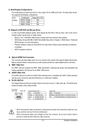
... device or a SATA port multiplier. Dual Display Configurations: This motherboard provides three ports for an IEEE 1394a device. The table below . • Memory: Two 1 GB DDR3 1066 memory modules with dual channel mode enabled • BIOS Setup: At least 256 MB of the LAN port LEDs. Dual Display Combination DVI-D + D-Sub...
... device or a SATA port multiplier. Dual Display Configurations: This motherboard provides three ports for an IEEE 1394a device. The table below . • Memory: Two 1 GB DDR3 1066 memory modules with dual channel mode enabled • BIOS Setup: At least 256 MB of the LAN port LEDs. Dual Display Combination DVI-D + D-Sub...
Manual
Page 39
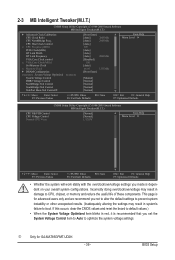
... or other unexpected results. (Inadequately altering the settings may result in red, it is recommended that you made is for GA-MA785GPMT-UD2H. - 39 - CPU Host Clock Control x CPU Frequency(MHz) PCIE Clock(MHz) HT Link Width HT ...Core Clock control x VGA Core Clock(MHz) Set Memory Clock x Memory Clock } DRAM Configuration ******** System Voltage Optimized ******** System Voltage Control DDR3 Voltage Control NorthBridge Volt Control SouthBridge Volt Control SidePort Mem Volt Controlj [Press Enter] [Auto] 2800Mhz [Auto] 2000Mhz [Auto] 200 [...
... or other unexpected results. (Inadequately altering the settings may result in red, it is recommended that you made is for GA-MA785GPMT-UD2H. - 39 - CPU Host Clock Control x CPU Frequency(MHz) PCIE Clock(MHz) HT Link Width HT ...Core Clock control x VGA Core Clock(MHz) Set Memory Clock x Memory Clock } DRAM Configuration ******** System Voltage Optimized ******** System Voltage Control DDR3 Voltage Control NorthBridge Volt Control SouthBridge Volt Control SidePort Mem Volt Controlj [Press Enter] [Auto] 2800Mhz [Auto] 2000Mhz [Auto] 200 [...
Manual
Page 42
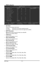
DRAM Configuration CMOS Setup Utility-Copyright (C) 1984-2009 Award Software DRAM Configuration DCTs Mode DDR3 Timing Items x CAS# latency x RAS to CAS R/W Delay x Row Precharge Time x Minimum RAS Active Time x 1T/2T Command Timing x TwTr Command Delay x Trfc0 ...for DIMM1 Options are : Auto (default), Manual. Auto 5T Auto 90ns Auto -- Unganged Sets memory control mode to two single-channel. (Default) DDR3 Timing Items Manual allows all DDR3 Timing items below to set memory control mode. RAS to CAS R/W Delay Options are : Auto (default), 90ns, 110ns, 160ns, 300ns, 350ns....
DRAM Configuration CMOS Setup Utility-Copyright (C) 1984-2009 Award Software DRAM Configuration DCTs Mode DDR3 Timing Items x CAS# latency x RAS to CAS R/W Delay x Row Precharge Time x Minimum RAS Active Time x 1T/2T Command Timing x TwTr Command Delay x Trfc0 ...for DIMM1 Options are : Auto (default), Manual. Auto 5T Auto 90ns Auto -- Unganged Sets memory control mode to two single-channel. (Default) DDR3 Timing Items Manual allows all DDR3 Timing items below to set memory control mode. RAS to CAS R/W Delay Options are : Auto (default), 90ns, 110ns, 160ns, 300ns, 350ns....
Manual
Page 43
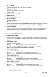
... North Bridge voltage by -0.1V to set the SidePort memory voltage. Manual allows all voltage control items below to be configurable. (Default: Manual) DDR3 Voltage Control Allows you to 0.750V at 0.1V increment. Normal Supplies the South Bridge voltage as required. (Default) -0.1V ~ +0.2V Increases South...0.3V at 0.1V increment. Note: Increasing memory voltage may result in damage to 0.3V at 0.1V increment. Trfc3 for GA-MA785GPMT-UD2H. - 43 - Normal Supplies the North Bridge voltage as required. Auto lets the BIOS automatically set the South Bridge voltage.
... North Bridge voltage by -0.1V to set the SidePort memory voltage. Manual allows all voltage control items below to be configurable. (Default: Manual) DDR3 Voltage Control Allows you to 0.750V at 0.1V increment. Normal Supplies the South Bridge voltage as required. (Default) -0.1V ~ +0.2V Increases South...0.3V at 0.1V increment. Note: Increasing memory voltage may result in damage to 0.3V at 0.1V increment. Trfc3 for GA-MA785GPMT-UD2H. - 43 - Normal Supplies the North Bridge voltage as required. Auto lets the BIOS automatically set the South Bridge voltage.

Manual
Page 56
... BIOS will show "No". Options are: Disabled (default), 60oC/140oF, 70oC/158oF, 80oC/176oF, 90oC/194oF. Current Voltage(V) Vcore/DDR3 1.5V/+3.3V/+12V Displays the current system voltages. 2-9 PC Health Status CMOS Setup Utility-Copyright (C) 1984-2009 Award Software PC Health ...Status Hardware Thermal Control Reset Case Open Status Case Opened Vcore DDR3 1.5V +3.3V +12V Current System Temperature Current CPU Temperature Current CPU FAN Speed Current SYSTEM FAN Speed Current NB FAN ...
... BIOS will show "No". Options are: Disabled (default), 60oC/140oF, 70oC/158oF, 80oC/176oF, 90oC/194oF. Current Voltage(V) Vcore/DDR3 1.5V/+3.3V/+12V Displays the current system voltages. 2-9 PC Health Status CMOS Setup Utility-Copyright (C) 1984-2009 Award Software PC Health ...Status Hardware Thermal Control Reset Case Open Status Case Opened Vcore DDR3 1.5V +3.3V +12V Current System Temperature Current CPU Temperature Current CPU FAN Speed Current SYSTEM FAN Speed Current NB FAN ...


