Manual
Page 4
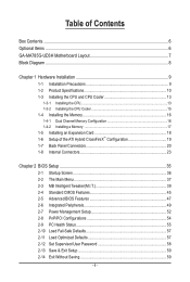
Table of Contents Box Contents...6 Optional Items...6 GA-MA785G-UD3H Motherboard Layout 7 Block Diagram...8 Chapter 1 Hardware Installation 9 1-1 Installation Precautions 9 1-2 Product Specifications 10 1-3 Installing the CPU and CPU Cooler 13 1-3-1 Installing the CPU 13 1-3-2 Installing the CPU Cooler 15 1-4 Installing the Memory 16 1-4-1 Dual Channel Memory Configuration 16 1-4-2 Installing a Memory 17 1-5 Installing an Expansion Card 18 1-6 Setup of the...
Table of Contents Box Contents...6 Optional Items...6 GA-MA785G-UD3H Motherboard Layout 7 Block Diagram...8 Chapter 1 Hardware Installation 9 1-1 Installation Precautions 9 1-2 Product Specifications 10 1-3 Installing the CPU and CPU Cooler 13 1-3-1 Installing the CPU 13 1-3-2 Installing the CPU Cooler 15 1-4 Installing the Memory 16 1-4-1 Dual Channel Memory Configuration 16 1-4-2 Installing a Memory 17 1-5 Installing an Expansion Card 18 1-6 Setup of the...
Manual
Page 8
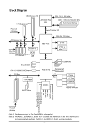
Block Diagram 1 PCI Express x16 1 PCI Express x4 (Note 2) AM3/AM2+/AM2 CPU CPU CLK+/- (200 MHz) DDR2 1333(O.C.)/1066/800 MHz Dual Channel Memory PCIe CLK (100 MHz) Hyper Transport 3.0 x4 x16 PCI Express Bus x1 x1 x1 ...
Block Diagram 1 PCI Express x16 1 PCI Express x4 (Note 2) AM3/AM2+/AM2 CPU CPU CLK+/- (200 MHz) DDR2 1333(O.C.)/1066/800 MHz Dual Channel Memory PCIe CLK (100 MHz) Hyper Transport 3.0 x4 x16 PCI Express Bus x1 x1 x1 ...
Manual
Page 9
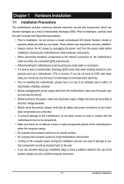
..., make sure the power supply has been turned off. • Before turning on the computer power during the installation process can become damaged as a motherboard, CPU or memory. These stickers are required for warranty validation. • Always remove the AC power by your hands dry and first touch a metal object to...
..., make sure the power supply has been turned off. • Before turning on the computer power during the installation process can become damaged as a motherboard, CPU or memory. These stickers are required for warranty validation. • Always remove the AC power by your hands dry and first touch a metal object to...
Manual
Page 10
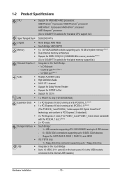
... II processor/ AMD Phenom™ processor/ AMD Athlon™ II processor/ AMD Athlon™ processor/ AMD Sempron™ processor (Go to GIGABYTE's website for the latest CPU support list.) 5200/2000 MT/s North Bridge: AMD 785G South Bridge: AMD SB710 4 x 1.8V DDR2 DIMM sockets supporting up to 16 ...GB of system memory (Note 1) Dual channel memory architecture Support for DDR2 1333(O.C.)/1066/800 MHz memory modules (Note 2) (Go to GIGABYTE's website for...
... II processor/ AMD Phenom™ processor/ AMD Athlon™ II processor/ AMD Athlon™ processor/ AMD Sempron™ processor (Go to GIGABYTE's website for the latest CPU support list.) 5200/2000 MT/s North Bridge: AMD 785G South Bridge: AMD SB710 4 x 1.8V DDR2 DIMM sockets supporting up to 16 ...GB of system memory (Note 1) Dual channel memory architecture Support for DDR2 1333(O.C.)/1066/800 MHz memory modules (Note 2) (Go to GIGABYTE's website for...
Manual
Page 11
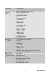
...1 x 24-pin ATX main power connector 1 x 8-pin ATX 12V power connector 1 x floppy disk drive connector 1 x IDE connector 6 x SATA 3Gb/s connectors 1 x CPU fan header 2 x system fan headers 1 x power fan header 1 x front panel header 1 x front panel audio header 1 x CD In connector 1 x S/PDIF In/... In/Line Out/Microphone) iTE IT8718 chip Hardware Monitor w w w w w w System voltage detection CPU/System temperature detection CPU/System/Power fan speed detection CPU overheating warning CPU/System/Power fan fail warning CPU/System fan speed control (Note 7) - 11 -
...1 x 24-pin ATX main power connector 1 x 8-pin ATX 12V power connector 1 x floppy disk drive connector 1 x IDE connector 6 x SATA 3Gb/s connectors 1 x CPU fan header 2 x system fan headers 1 x power fan header 1 x front panel header 1 x front panel audio header 1 x CD In connector 1 x S/PDIF In/... In/Line Out/Microphone) iTE IT8718 chip Hardware Monitor w w w w w w System voltage detection CPU/System temperature detection CPU/System/Power fan speed detection CPU overheating warning CPU/System/Power fan fail warning CPU/System fan speed control (Note 7) - 11 -
Manual
Page 12
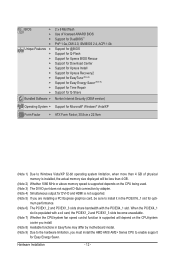
... install it in EasyTune may differ by adapter. (Note 4) Simultaneous output for DVI-D and HDMI is supported will depend on the CPU/system cooler you install. (Note 8) Available functions in the PCIEX16_1 slot for Easy Energy Saver. Hardware Installation - 12 - BIOS w w w w Unique Features w w w w w ...memory size displayed will be less than 4 GB. (Note 2) Whether 1066 MHz or above memory speed is supported depends on the CPU being used. (Note 3) The DVI-D port does not support D-Sub connection by motherboard model. (Note 9) Due to the ...
... install it in EasyTune may differ by adapter. (Note 4) Simultaneous output for DVI-D and HDMI is supported will depend on the CPU/system cooler you install. (Note 8) Available functions in the PCIEX16_1 slot for Easy Energy Saver. Hardware Installation - 12 - BIOS w w w w Unique Features w w w w w ...memory size displayed will be less than 4 GB. (Note 2) Whether 1066 MHz or above memory speed is supported depends on the CPU being used. (Note 3) The DVI-D port does not support D-Sub connection by motherboard model. (Note 9) Due to the ...
Manual
Page 13
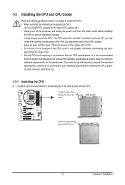
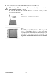
...; Do not turn off the computer and unplug the power cord from the power outlet before you begin to install the CPU: • Make sure that the system bus frequency be inserted if oriented incorrectly. (Or you wish to set the frequency beyond the standard specifications, ...please do so according to GIGABYTE's website for the peripherals. The CPU cannot be set beyond hardware specifications since it does not meet the standard requirements for the latest...
...; Do not turn off the computer and unplug the power cord from the power outlet before you begin to install the CPU: • Make sure that the system bus frequency be inserted if oriented incorrectly. (Or you wish to set the frequency beyond the standard specifications, ...please do so according to GIGABYTE's website for the peripherals. The CPU cannot be set beyond hardware specifications since it does not meet the standard requirements for the latest...
Manual
Page 14
...) with the triangle mark on the middle of the CPU, lowering the locking lever and latching it into their holes. Adjust the CPU orientation if this occurs. The CPU cannot fit in if oriented incorrectly. Make sure that the CPU pins fit perfectly into the fully locked position. Hardware ...Installation - 14 - Follow the steps below to correctly install the CPU into the motherboard CPU socket. • Before installing the CPU, make sure to turn off the computer and ...
...) with the triangle mark on the middle of the CPU, lowering the locking lever and latching it into their holes. Adjust the CPU orientation if this occurs. The CPU cannot fit in if oriented incorrectly. Make sure that the CPU pins fit perfectly into the fully locked position. Hardware ...Installation - 14 - Follow the steps below to correctly install the CPU into the motherboard CPU socket. • Before installing the CPU, make sure to turn off the computer and ...
Manual
Page 15
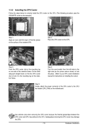
... the example.) Step 1: Apply an even and thin layer of thermal grease on the surface of the installed CPU. 1-3-2 Installing the CPU Cooler Follow the steps below to correctly install the CPU cooler on the CPU. (The following procedure uses the GIGABYTE cooler as the picture above shows) to lock into place. (Refer to your...
... the example.) Step 1: Apply an even and thin layer of thermal grease on the surface of the installed CPU. 1-3-2 Installing the CPU Cooler Follow the steps below to correctly install the CPU cooler on the CPU. (The following procedure uses the GIGABYTE cooler as the picture above shows) to lock into place. (Refer to your...
Manual
Page 16
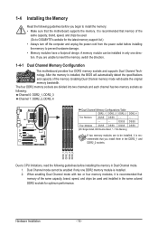
... 1-4-1 Dual Channel Memory Configuration This motherboard provides four DDR2 memory sockets and supports Dual Channel Technology. DDR2_1 DDR2_2 DDR2_3 DDR2_4 Due to CPU limitations, read the following guidelines before installing the memory to prevent hardware damage. • Memory modules have a foolproof design. 1-4 ...the memory: • Make sure that memory of the same capacity, brand, speed, and chips be used . (Go to GIGABYTE's website for optimum performance. It is recommended that you install them in only one DDR2 memory module is recommended that the motherboard ...
... 1-4-1 Dual Channel Memory Configuration This motherboard provides four DDR2 memory sockets and supports Dual Channel Technology. DDR2_1 DDR2_2 DDR2_3 DDR2_4 Due to CPU limitations, read the following guidelines before installing the memory to prevent hardware damage. • Memory modules have a foolproof design. 1-4 ...the memory: • Make sure that memory of the same capacity, brand, speed, and chips be used . (Go to GIGABYTE's website for optimum performance. It is recommended that you install them in only one DDR2 memory module is recommended that the motherboard ...
Manual
Page 21
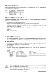
... configurations. Use this feature, ensure that supports digital optical audio. Do not rock it straight out from the connector. Hardware Installation A. The table below . • CPU: AMD Athlon™ LE1640 processor or above • Memory: Two 1 GB DDR2 800 MHz memory modules with dual channel mode enabled • BIOS Setup: At...
... configurations. Use this feature, ensure that supports digital optical audio. Do not rock it straight out from the connector. Hardware Installation A. The table below . • CPU: AMD Athlon™ LE1640 processor or above • Memory: Two 1 GB DDR2 800 MHz memory modules with dual channel mode enabled • BIOS Setup: At...
Manual
Page 24
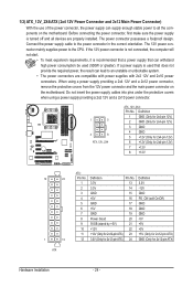
...). 1/2) ATX_12V_2X4/ATX (2x4 12V Power Connector and 2x12 Main Power Connector) With the use of the power connector, the power supply can lead to the CPU.
...). 1/2) ATX_12V_2X4/ATX (2x4 12V Power Connector and 2x12 Main Power Connector) With the use of the power connector, the power supply can lead to the CPU.
Manual
Page 25
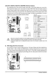
... drive, be installed inside the chassis. Hardware Installation Most fan headers possess a foolproof insertion design. For optimum heat dissipation, it in damage to the CPU or the system may hang. • These fan headers are : 360 KB, 720 KB, 1.2 MB, 1.44 MB, and 2.88 MB. ... to connect fan cables to the fan headers to connect it is typically designated by a stripe of a CPU fan with fan speed control design. When connecting a fan cable, be sure to prevent your CPU and system from overheating. 3/4/5) CPU_FAN/SYS_FAN1/SYS_FAN2/PWR_FAN (Fan Headers) The motherboard has a 4-pin...
... drive, be installed inside the chassis. Hardware Installation Most fan headers possess a foolproof insertion design. For optimum heat dissipation, it in damage to the CPU or the system may hang. • These fan headers are : 360 KB, 720 KB, 1.2 MB, 1.44 MB, and 2.88 MB. ... to connect fan cables to the fan headers to connect it is typically designated by a stripe of a CPU fan with fan speed control design. When connecting a fan cable, be sure to prevent your CPU and system from overheating. 3/4/5) CPU_FAN/SYS_FAN1/SYS_FAN2/PWR_FAN (Fan Headers) The motherboard has a 4-pin...
Manual
Page 37
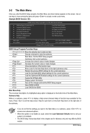
... Optimized Defaults Set Supervisor Password Set User Password Save & Exit Setup Exit Without Saving ESC: Quit F8: Q-Flash Select Item F10: Save & Exit Setup Change CPU's Clock & Voltage F11: Save CMOS to BIOS F12: Load CMOS from BIOS Main Menu Help The on-screen description of a highlighted setup option is displayed...
... Optimized Defaults Set Supervisor Password Set User Password Save & Exit Setup Exit Without Saving ESC: Quit F8: Q-Flash Select Item F10: Save & Exit Setup Change CPU's Clock & Voltage F11: Save CMOS to BIOS F12: Load CMOS from BIOS Main Menu Help The on-screen description of a highlighted setup option is displayed...
Manual
Page 38
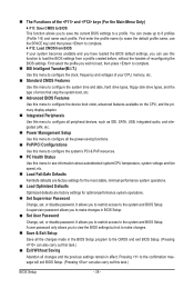
... the BIOS Setup program to the CMOS and exit BIOS Setup. (Pressing can also carry out this menu to see information about autodetected system/CPU temperature, system voltage and fan speed, etc. Load Fail-Safe Defaults Fail-Safe defaults are factory settings for the most stable,... that stop the system boot, etc. Advanced BIOS Features Use this menu to configure the device boot order, advanced features available on the CPU, and the primary display adapter. Integrated Peripherals Use this menu to configure all peripheral devices, such as IDE, SATA, USB, integrated audio...
... the BIOS Setup program to the CMOS and exit BIOS Setup. (Pressing can also carry out this menu to see information about autodetected system/CPU temperature, system voltage and fan speed, etc. Load Fail-Safe Defaults Fail-Safe defaults are factory settings for the most stable,... that stop the system boot, etc. Advanced BIOS Features Use this menu to configure the device boot order, advanced features available on the CPU, and the primary display adapter. Integrated Peripherals Use this menu to configure all peripheral devices, such as IDE, SATA, USB, integrated audio...
Manual
Page 39
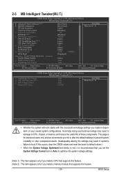
...Core Clock control x VGA Core Clock(MHz) EPP Mode (Note 2) x EPP Voltage Control (Note 2) CPU Clock Ratio CPU NorthBridge Freq. (Note 1) CPU Host Clock Control x CPU Frequency(MHz) PCIE Clock(MHz) Set Memory Clock x Memory Clock DCTs Mode System Voltage Optimized ******** System... CMOS Setup Utility-Copyright (C) 1984-2009 Award Software MB Intelligent Tweaker(M.I.T.) x SouthBridge Volt Control x CPU NB VID Control (Note 1) x CPU Voltage Control Normal CPU Vcore Auto Auto Auto 1.3250V Item Help Menu Level Move Enter: Select F5: Previous ...
...Core Clock control x VGA Core Clock(MHz) EPP Mode (Note 2) x EPP Voltage Control (Note 2) CPU Clock Ratio CPU NorthBridge Freq. (Note 1) CPU Host Clock Control x CPU Frequency(MHz) PCIE Clock(MHz) Set Memory Clock x Memory Clock DCTs Mode System Voltage Optimized ******** System... CMOS Setup Utility-Copyright (C) 1984-2009 Award Software MB Intelligent Tweaker(M.I.T.) x SouthBridge Volt Control x CPU NB VID Control (Note 1) x CPU Voltage Control Normal CPU Vcore Auto Auto Auto 1.3250V Item Help Menu Level Move Enter: Select F5: Previous ...
Manual
Page 40
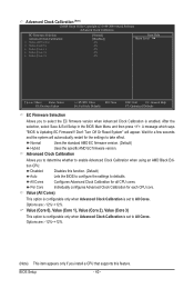
... BIOS Setup - 40 - A message which says "BIOS Is Updating EC Firmware!!! Advanced Clock Calibration Allows you install a CPU that supports this function. (Default) Auto Lets the BIOS to configure the settings to defaults. Per Core Individually configures Advanced Clock ...12%~+12%. (Note) This item appears only if you to determine whether to enable Advanced Clock Calibration when using an AMD Black Edition CPU. Advanced Clock Calibration (Note) CMOS Setup Utility-Copyright (C) 1984-2009 Award Software Advanced Clock Calibration EC Firmware Selection Advanced Clock Calibration x...
... BIOS Setup - 40 - A message which says "BIOS Is Updating EC Firmware!!! Advanced Clock Calibration Allows you install a CPU that supports this function. (Default) Auto Lets the BIOS to configure the settings to defaults. Per Core Individually configures Advanced Clock ...12%~+12%. (Note) This item appears only if you to determine whether to enable Advanced Clock Calibration when using an AMD Black Edition CPU. Advanced Clock Calibration (Note) CMOS Setup Utility-Copyright (C) 1984-2009 Award Software Advanced Clock Calibration EC Firmware Selection Advanced Clock Calibration x...
Manual
Page 42
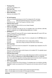
... option is installed. Normal Lets the BIOS optimize memory voltage settings. (Default) By EPP Sets memory voltage according to automatically adjust the CPU host frequency. Note: If your system fails to boot after overclocking, please wait for 20 seconds to Auto. EPP Mode (Note 1)... disables the control of VGA Core clock. (Default: Disabled) VGA Core Clock(MHz) Allows you to manually set to allow for the installed CPU. CPU NorthBridge Freq. (Note 2) Allows you to alter the North Bridge controller frequency for EPP memory to enhance performance. (Default: Disabled) EPP Voltage...
... option is installed. Normal Lets the BIOS optimize memory voltage settings. (Default) By EPP Sets memory voltage according to automatically adjust the CPU host frequency. Note: If your system fails to boot after overclocking, please wait for 20 seconds to Auto. EPP Mode (Note 1)... disables the control of VGA Core clock. (Default: Disabled) VGA Core Clock(MHz) Allows you to manually set to allow for the installed CPU. CPU NorthBridge Freq. (Note 2) Allows you to alter the North Bridge controller frequency for EPP memory to enhance performance. (Default: Disabled) EPP Voltage...
Manual
Page 43
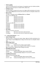
... whether to Manual. Manual allows all voltage control items below to be configurable. (Default: Auto) DDR2 Voltage Control Allows you use an AM3/AM2+ CPU: X2.00 Sets Memory Clock to 0.3V at 0.1V increment. Manual allows the memory clock control item below to be configurable. (Default: Auto) ...33. DDR 533 Sets Memory Clock to DDR 800. DDR 800 Sets Memory Clock to DDR 533. DCTs Mode Allows you use an AM2 CPU: DDR 400 Sets Memory Clock to 200 MHz. Ganged Sets memory control mode to set memory control mode. Normal Supplies the North Bridge voltage...
... whether to Manual. Manual allows all voltage control items below to be configurable. (Default: Auto) DDR2 Voltage Control Allows you use an AM3/AM2+ CPU: X2.00 Sets Memory Clock to 0.3V at 0.1V increment. Manual allows the memory clock control item below to be configurable. (Default: Auto) ...33. DDR 533 Sets Memory Clock to DDR 800. DDR 800 Sets Memory Clock to DDR 533. DCTs Mode Allows you use an AM2 CPU: DDR 400 Sets Memory Clock to 200 MHz. Ganged Sets memory control mode to set memory control mode. Normal Supplies the North Bridge voltage...
Manual
Page 44
... Displays the normal operating voltage of your CPU or reduce the useful life of the CPU. The adjustable range is dependent on the CPU being installed. (Default: Normal) Note: Increasing CPU voltage may result in damage to your CPU or reduce the useful life of the CPU. CPU NB VID Control (Note) Allows you to set the...
... Displays the normal operating voltage of your CPU or reduce the useful life of the CPU. The adjustable range is dependent on the CPU being installed. (Default: Normal) Note: Increasing CPU voltage may result in damage to your CPU or reduce the useful life of the CPU. CPU NB VID Control (Note) Allows you to set the...


