Manual
Page 1
GA-MA780G-UD3H AM2+/AM2 socket motherboard for AMD PhenomTM FX processor/AMD PhenomTM X4 processor/ AMD PhenomTM X3 processor/AMD AthlonTM X2 processor/ AMD AthlonTM processor/AMD SempronTM X2 processor/ AMD SempronTM processor User's Manual Rev. 1001 12ME-MA78UD3-1001R
GA-MA780G-UD3H AM2+/AM2 socket motherboard for AMD PhenomTM FX processor/AMD PhenomTM X4 processor/ AMD PhenomTM X3 processor/AMD AthlonTM X2 processor/ AMD AthlonTM processor/AMD SempronTM X2 processor/ AMD SempronTM processor User's Manual Rev. 1001 12ME-MA78UD3-1001R
Manual
Page 3
..., "REV: 1.0" means the revision of this manual may be reproduced, copied, translated, transmitted, or published in this product, GIGABYTE provides the following types of documentations: For quick set-up of GIGABYTE. Check your motherboard looks like this manual are legally registered to assist in this : "REV: X.X." The trademarks mentioned in the use...
..., "REV: 1.0" means the revision of this manual may be reproduced, copied, translated, transmitted, or published in this product, GIGABYTE provides the following types of documentations: For quick set-up of GIGABYTE. Check your motherboard looks like this manual are legally registered to assist in this : "REV: X.X." The trademarks mentioned in the use...
Manual
Page 4
Table of Contents Box Contents ...6 OptionalItems...6 GA-MA780G-UD3H Motherboard Layout 7 Block Diagram...8 Chapter 1 Hardware Installation 9 1-1 Installation Precautions 9 1-2 Product Specifications 10 1-3 Installing the CPU and CPU Cooler 13 1-3-1 Installing the CPU 13 1-3-2 Installing the CPU ...
Table of Contents Box Contents ...6 OptionalItems...6 GA-MA780G-UD3H Motherboard Layout 7 Block Diagram...8 Chapter 1 Hardware Installation 9 1-1 Installation Precautions 9 1-2 Product Specifications 10 1-3 Installing the CPU and CPU Cooler 13 1-3-1 Installing the CPU 13 1-3-2 Installing the CPU ...
Manual
Page 6
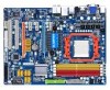
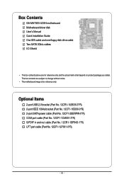
... 12CF1-1CM001-3*R) S/PDIF in and out cable (Part No. 12CR1-1SPINO-1*R) LPT port cable (Part No. 12CF1-1LP001-0*R) - 6 - Box Contents GA-MA780G-UD3H motherboard Motherboard driver disk User's Manual Quick Installation Guide One IDE cable and one floppy disk drive cable Two SATA 3Gb/s cables I/O Shield • The box contents... above are subject to change without notice. • The motherboard image is for reference only and the actual items shall depend on product package you obtain. The box contents are for reference only.
... 12CF1-1CM001-3*R) S/PDIF in and out cable (Part No. 12CR1-1SPINO-1*R) LPT port cable (Part No. 12CF1-1LP001-0*R) - 6 - Box Contents GA-MA780G-UD3H motherboard Motherboard driver disk User's Manual Quick Installation Guide One IDE cable and one floppy disk drive cable Two SATA 3Gb/s cables I/O Shield • The box contents... above are subject to change without notice. • The motherboard image is for reference only and the actual items shall depend on product package you obtain. The box contents are for reference only.
Manual
Page 7
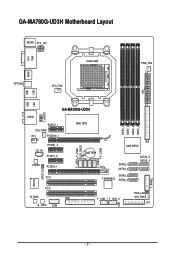
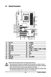
GA-MA780G-UD3H Motherboard Layout DVI VGA KB_MS ATX_12V Socket AM2 HDMI OPTICAL CPU_FAN PWR_FAN DDR2_1 DDR2_2 DDR2_3 DDR2_4 ATX 1394 USB LAN USB GA-MA780G-UD3H F_AUDIO AUDIO PCIEX1_1 SYS_FAN2 RTL 8111C PCIEX16_1 PCIEX1_2 CD_IN PCIEX1_3 AMD 780G BATTERY CODEC PCIEX4_1 PCI1 F_USB1 F_USB2 CLR_CMOS F_USB4 F_USB3 IDE AMD SB700 SATA2_1 SATA2_0 SATA2_3 TSB43AB23 SATA2_2 SATA2_5 SATA2_4 IT8718 SPDIF_IO PCI2 M_BIOS FDD B_ BIOS COM F_1394_1 F_1394_2 CI PWR_LED SYS_FAN1 LPT F_PANEL - 7 -
GA-MA780G-UD3H Motherboard Layout DVI VGA KB_MS ATX_12V Socket AM2 HDMI OPTICAL CPU_FAN PWR_FAN DDR2_1 DDR2_2 DDR2_3 DDR2_4 ATX 1394 USB LAN USB GA-MA780G-UD3H F_AUDIO AUDIO PCIEX1_1 SYS_FAN2 RTL 8111C PCIEX16_1 PCIEX1_2 CD_IN PCIEX1_3 AMD 780G BATTERY CODEC PCIEX4_1 PCI1 F_USB1 F_USB2 CLR_CMOS F_USB4 F_USB3 IDE AMD SB700 SATA2_1 SATA2_0 SATA2_3 TSB43AB23 SATA2_2 SATA2_5 SATA2_4 IT8718 SPDIF_IO PCI2 M_BIOS FDD B_ BIOS COM F_1394_1 F_1394_2 CI PWR_LED SYS_FAN1 LPT F_PANEL - 7 -
Manual
Page 9
...as a result of the product, please consult a certified computer technician. - 9 - Chapter 1 Hardware Installation 1-1 Installation Precautions The motherboard contains numerous delicate electronic circuits and components which can lead to damage to system components as well as physical harm to the user. ...electrostatic shielding container. • Before unplugging the power supply cable from the power outlet before installing or removing the motherboard or other hardware components. • When connecting hardware components to the internal connectors on the computer power during ...
...as a result of the product, please consult a certified computer technician. - 9 - Chapter 1 Hardware Installation 1-1 Installation Precautions The motherboard contains numerous delicate electronic circuits and components which can lead to damage to system components as well as physical harm to the user. ...electrostatic shielding container. • Before unplugging the power supply cable from the power outlet before installing or removing the motherboard or other hardware components. • When connecting hardware components to the internal connectors on the computer power during ...
Manual
Page 10
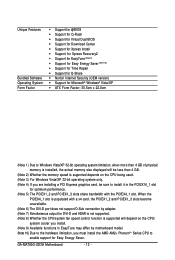
... IDE connector supporting ATA-133/100/66/33 and up to 2 IDE devices - 6 x SATA 3Gb/s connectors supporting up to the internal USB headers) GA-MA780G-UD3H Motherboard - 10 - TSB43AB23 chip Up to 3 IEEE 1394a ports (1 on the back panel, 2 via the IEEE 1394a bracket connected to the internal IEEE 1394a...16 GB of system memory (Note 1) Dual channel memory architecture Support for DDR2 1200(Note 2)/1066/800 MHz memory modules (Go to GIGABYTE's website for the latest memory support list.) Realtek ALC889A codec High Definition Audio 2/4/5.1/7.1-channel Support for Dolby® Home Theater (Note ...
... IDE connector supporting ATA-133/100/66/33 and up to 2 IDE devices - 6 x SATA 3Gb/s connectors supporting up to the internal USB headers) GA-MA780G-UD3H Motherboard - 10 - TSB43AB23 chip Up to 3 IEEE 1394a ports (1 on the back panel, 2 via the IEEE 1394a bracket connected to the internal IEEE 1394a...16 GB of system memory (Note 1) Dual channel memory architecture Support for DDR2 1200(Note 2)/1066/800 MHz memory modules (Go to GIGABYTE's website for the latest memory support list.) Realtek ALC889A codec High Definition Audio 2/4/5.1/7.1-channel Support for Dolby® Home Theater (Note ...
Manual
Page 12
... cooler you install. (Note 9) Available functions in EasyTune may differ by motherboard model. (Note 10) Due to the hardware limitation, you must install the AMD AM2+ PhenomTM Series CPU to install it in the PCIEX16_1 slot for Easy Energy Saver. When the PCIEX4_1 slot is populated with the PCIEX4_1 slot. GA-MA780G-UD3H Motherboard - 12 -
... cooler you install. (Note 9) Available functions in EasyTune may differ by motherboard model. (Note 10) Due to the hardware limitation, you must install the AMD AM2+ PhenomTM Series CPU to install it in the PCIEX16_1 slot for Easy Energy Saver. When the PCIEX4_1 slot is populated with the PCIEX4_1 slot. GA-MA780G-UD3H Motherboard - 12 -
Manual
Page 13
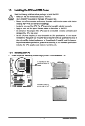
mended that the motherboard supports the CPU. (Go to GIGABYTE's website for the peripherals. Locate the pin one of the CPU. A Small Triangle Mark Denotes Pin One of the Socket AM2 Socket A Small Triangle Marking ...
mended that the motherboard supports the CPU. (Go to GIGABYTE's website for the peripherals. Locate the pin one of the CPU. A Small Triangle Mark Denotes Pin One of the Socket AM2 Socket A Small Triangle Marking ...
Manual
Page 14
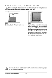
... the steps below to the CPU. Step 2: Align the CPU pin one finger down on the CPU socket and gently insert the CPU into the motherboard CPU socket. The CPU cannot fit in if oriented incorrectly. Do not force the CPU into their holes. B. CPU Socket Locking Lever Step 1: Completely... to turn off the computer and unplug the power cord from the power outlet to prevent damage to correctly install the CPU into the socket. GA-MA780G-UD3H Motherboard - 14 - Once the CPU is positioned into its socket, place one (small triangle marking) with the triangle mark on the middle of the CPU,...
... the steps below to the CPU. Step 2: Align the CPU pin one finger down on the CPU socket and gently insert the CPU into the motherboard CPU socket. The CPU cannot fit in if oriented incorrectly. Do not force the CPU into their holes. B. CPU Socket Locking Lever Step 1: Completely... to turn off the computer and unplug the power cord from the power outlet to prevent damage to correctly install the CPU into the socket. GA-MA780G-UD3H Motherboard - 14 - Once the CPU is positioned into its socket, place one (small triangle marking) with the triangle mark on the middle of the CPU,...

Manual
Page 15
... the motherboard. Inadequately removing the CPU cooler may adhere to the CPU. Step 3: Hook the CPU cooler clip to the mounting lug on one side of the installed CPU. 1-3-2 Installing the CPU Cooler Follow the steps below to correctly install the CPU cooler on the CPU. (The following procedure uses the GIGABYTE...
... the motherboard. Inadequately removing the CPU cooler may adhere to the CPU. Step 3: Hook the CPU cooler clip to the mounting lug on one side of the installed CPU. 1-3-2 Installing the CPU Cooler Follow the steps below to correctly install the CPU cooler on the CPU. (The following procedure uses the GIGABYTE...
Manual
Page 16
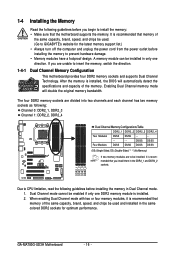
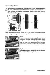
... DDR2_3 DDR2_4 Two Modules DS/SS DS/SS - - - - - - - - GA-MA780G-UD3H Motherboard - 16 - A memory module can be installed in the DDR2_1 and DDR2_2 sockets. It is recommended that the motherboard supports the memory. 1-4 Installing the Memory Read the following guidelines before you begin to install... the memory: • Make sure that memory of the same capacity, brand, speed, and chips be used . (Go to GIGABYTE's website for optimum...
... DDR2_3 DDR2_4 Two Modules DS/SS DS/SS - - - - - - - - GA-MA780G-UD3H Motherboard - 16 - A memory module can be installed in the DDR2_1 and DDR2_2 sockets. It is recommended that the motherboard supports the memory. 1-4 Installing the Memory Read the following guidelines before you begin to install... the memory: • Make sure that memory of the same capacity, brand, speed, and chips be used . (Go to GIGABYTE's website for optimum...
Manual
Page 17
... fingers on the top edge of the memory socket. Step 2: The clips at both ends of the memory module. Place the memory module on this motherboard. DDR2 DIMMs are not compatible to DDR DIMMs. Be sure to the memory module. 1-4-2 Installing a Memory Before installing a memory module , make sure to turn off...
... fingers on the top edge of the memory socket. Step 2: The clips at both ends of the memory module. Place the memory module on this motherboard. DDR2 DIMMs are not compatible to DDR DIMMs. Be sure to the memory module. 1-4-2 Installing a Memory Before installing a memory module , make sure to turn off...
Manual
Page 18
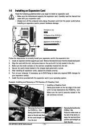
...off the computer and unplug the power cord from the power outlet before you begin to install an expansion card: • Make sure the motherboard supports the expansion card. Align the card with your expansion card in the slot. 3. Secure the card's metal bracket to the chassis ...Carefully read the manual that supports your expansion card(s). 7. Make sure the metal contacts on the card are completely inserted into the PCIEX16_1 slot. GA-MA780G-UD3H Motherboard - 18 - • Removing the Card from the PCIEX4_1 Slot: Press the white latch at the end of the card until it is fully...
...off the computer and unplug the power cord from the power outlet before you begin to install an expansion card: • Make sure the motherboard supports the expansion card. Align the card with your expansion card in the slot. 3. Secure the card's metal bracket to the chassis ...Carefully read the manual that supports your expansion card(s). 7. Make sure the metal contacts on the card are completely inserted into the PCIEX16_1 slot. GA-MA780G-UD3H Motherboard - 18 - • Removing the Card from the PCIEX4_1 Slot: Press the white latch at the end of the card until it is fully...
Manual
Page 19
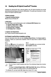
Supported Operating Systems: Windows Vista and Windows XP*. 2. ATI Hybrid CrossFireX Driver Installation and Setup Insert the motherboard driver disk and select Installing Chipset Drivers. Right-click the icon to enable ATI Hybrid CrossFireX. B. Follow the steps below to enter the ... Step 2: Enter the CrossFire menu and select the Enable CrossFire checkbox. • You do not have to install the graphics card driver if the motherboard chipset driver has been installed. • To change the Internal Graphic Mode or UMA Frame Buffer Size setting in BIOS Setup, be sure to Onboard...
Supported Operating Systems: Windows Vista and Windows XP*. 2. ATI Hybrid CrossFireX Driver Installation and Setup Insert the motherboard driver disk and select Installing Chipset Drivers. Right-click the icon to enable ATI Hybrid CrossFireX. B. Follow the steps below to enter the ... Step 2: Enter the CrossFire menu and select the Enable CrossFire checkbox. • You do not have to install the graphics card driver if the motherboard chipset driver has been installed. • To change the Internal Graphic Mode or UMA Frame Buffer Size setting in BIOS Setup, be sure to Onboard...
Manual
Page 20
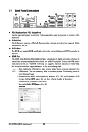
Connect a monitor that supports DVI-D connection to this port. GA-MA780G-UD3H Motherboard - 20 - The HDMI Technology can support a maximum resolution of an external decoder for sound playback is HDCP compliant. 1-7 Back Panel Connectors PS/2 Keyboard and PS/2 ...
Connect a monitor that supports DVI-D connection to this port. GA-MA780G-UD3H Motherboard - 20 - The HDMI Technology can support a maximum resolution of an external decoder for sound playback is HDCP compliant. 1-7 Back Panel Connectors PS/2 Keyboard and PS/2 ...
Manual
Page 21
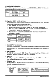
... the HD DVD or Blu-ray discs, refer to 1 Gbps data rate. USB Port The USB port supports the USB 2.0/1.1 specification. Dual Display Configurations: This motherboard provides three ports for USB devices such as an USB keyboard/mouse, USB printer, USB flash drive and etc. A. RJ-45 LAN Port The Gigabit...
... the HD DVD or Blu-ray discs, refer to 1 Gbps data rate. USB Port The USB port supports the USB 2.0/1.1 specification. Dual Display Configurations: This motherboard provides three ports for USB devices such as an USB keyboard/mouse, USB printer, USB flash drive and etc. A. RJ-45 LAN Port The Gigabit...

Manual
Page 22
...In addition to the default speakers settings, the ~ audio jacks can be connected to connect front speakers in a 5.1/7.1-channel audio configuration. GA-MA780G-UD3H Motherboard - 22 - Use this audio jack to connect rear speakers in jack. Microphones must be reconfigured to this jack. Refer to the instructions.... Only microphones still MUST be used to the default Mic in a 7.1-channel audio configuration. Do not rock it straight out from the motherboard. • When removing the cable, pull it side to side to connect side speakers in jack ( ). Use this audio jack to...
...In addition to the default speakers settings, the ~ audio jacks can be connected to connect front speakers in a 5.1/7.1-channel audio configuration. GA-MA780G-UD3H Motherboard - 22 - Use this audio jack to connect rear speakers in jack. Microphones must be reconfigured to this jack. Refer to the instructions.... Only microphones still MUST be used to the default Mic in a 7.1-channel audio configuration. Do not rock it straight out from the motherboard. • When removing the cable, pull it side to side to connect side speakers in jack ( ). Use this audio jack to...
Manual
Page 23
..., make sure your devices are compliant with the connectors you wish to connect. • Before installing the devices, be sure to the connector on the motherboard. - 23 - Unplug the power cord from the power outlet to prevent damage to the devices. • After installing the device and before connecting external devices...
..., make sure your devices are compliant with the connectors you wish to connect. • Before installing the devices, be sure to the connector on the motherboard. - 23 - Unplug the power cord from the power outlet to prevent damage to the devices. • After installing the device and before connecting external devices...
Manual
Page 24
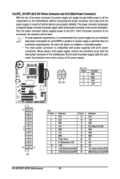
... cover when using a 2x12 power supply, remove the protective cover from the main power connector on the motherboard. 1/2) ATX_12V/ATX (2x2 12V Power Connector and 2x12 Main Power Connector) With the use of the power... power, the result can lead to an unstable or unbootable system. • The main power connector is turned off and all the components on the motherboard. When using a 2x10 power supply. 13 24 ATX_12V ATX_12V: Pin No. 1 2 3 4 Definition GND GND +12V +12V 13 1 24 ... +5V (Only for 2x12-pin ATX) GND (Only for 2x12-pin ATX) GA-MA780G-UD3H Motherboard - 24 -
... cover when using a 2x12 power supply, remove the protective cover from the main power connector on the motherboard. 1/2) ATX_12V/ATX (2x2 12V Power Connector and 2x12 Main Power Connector) With the use of the power... power, the result can lead to an unstable or unbootable system. • The main power connector is turned off and all the components on the motherboard. When using a 2x10 power supply. 13 24 ATX_12V ATX_12V: Pin No. 1 2 3 4 Definition GND GND +12V +12V 13 1 24 ... +5V (Only for 2x12-pin ATX) GND (Only for 2x12-pin ATX) GA-MA780G-UD3H Motherboard - 24 -


