Manual
Page 1
GA-MA770-UD3/ GA-MA770-US3 AM2+/AM2 socket motherboard for AMD PhenomTM FX processor/AMD PhenomTM X4 processor/ AMD PhenomTM X3 processor/AMD AthlonTM X2 processor/ AMD AthlonTM processor/AMD SempronTM X2 processor/ AMD SempronTM processor User's Manual Rev. 1001 12ME-MA77UDS3-1001R
GA-MA770-UD3/ GA-MA770-US3 AM2+/AM2 socket motherboard for AMD PhenomTM FX processor/AMD PhenomTM X4 processor/ AMD PhenomTM X3 processor/AMD AthlonTM X2 processor/ AMD AthlonTM processor/AMD SempronTM X2 processor/ AMD SempronTM processor User's Manual Rev. 1001 12ME-MA77UDS3-1001R
Manual
Page 7
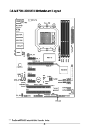
GA-MA770-UD3/US3 Motherboard Layout KB_MS SYS_FAN2 CPU_FAN Socket AM2 RCA_SPDIF ATX R_USB USB_1394_1 USB_1394_2 USB_LAN GA-MA770-UD3/US3 DDRII_1 DDRII_2 DDRII_3 DDRII_4 PWR_FAN F_AUDIO AUDIO ATX_12V PCIE_1 NB_FAN AMD 770 RTL8111C PCIE_2 CD_IN SPDIF_IN CODEC PCIE_3 SPDIF_OUT PCIE_4 TSB43AB23 PCI1 PCI2 F1_1394 COMA PCIE_16 IDE AMD SB700 Main BIOS F_USB1 BAT CLR_CMOS Backup BIOS F_USB2 SATAII1 SATAII3 SATAII0 CI SATAII2 IT8720 SATAII5 SATAII4 LPT FDD SYS_FAN1 F_PANEL PWR_LED "*" The GA-MA770-UD3 adopt All-Solid Capacitor design. - 7 -
GA-MA770-UD3/US3 Motherboard Layout KB_MS SYS_FAN2 CPU_FAN Socket AM2 RCA_SPDIF ATX R_USB USB_1394_1 USB_1394_2 USB_LAN GA-MA770-UD3/US3 DDRII_1 DDRII_2 DDRII_3 DDRII_4 PWR_FAN F_AUDIO AUDIO ATX_12V PCIE_1 NB_FAN AMD 770 RTL8111C PCIE_2 CD_IN SPDIF_IN CODEC PCIE_3 SPDIF_OUT PCIE_4 TSB43AB23 PCI1 PCI2 F1_1394 COMA PCIE_16 IDE AMD SB700 Main BIOS F_USB1 BAT CLR_CMOS Backup BIOS F_USB2 SATAII1 SATAII3 SATAII0 CI SATAII2 IT8720 SATAII5 SATAII4 LPT FDD SYS_FAN1 F_PANEL PWR_LED "*" The GA-MA770-UD3 adopt All-Solid Capacitor design. - 7 -

Manual
Page 8
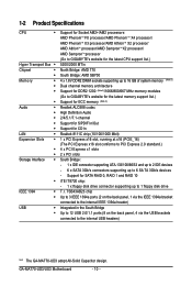
Block Diagram PCIe CLK (100 MHz) 1 PCI Express x16 PCI Express x16 AMD Socket AM2+/AM2 CPU CPU CLK+/-(200 MHz) DDR2 1200/1066/800/667 MHz Dual Channel Memory Hyper Transport 3.0 PCI Express Bus x1 x1 x1 x1 AMD 770 PCIe CLK x1 (100 MHz) 4 PCI Express x1 RTL8111C RJ45 LAN PCI Bus TSB43AB23 3 IEEE 1394a AMD SB700 CODEC ATA-133/100/66/33 IDE Channel 6 SATA 3Gb/s 12 USB Ports IT8720 Dual BIOS Floppy LPT Port COM Port PS/2 KB/Mouse Surround Speaker Out Center/Subwoofer Speaker Out Side Speaker Out MIC Line-Out Line-In SPDIF In SPDIF Out 2 PCI PCI CLK (33 MHz) - 8 -
Block Diagram PCIe CLK (100 MHz) 1 PCI Express x16 PCI Express x16 AMD Socket AM2+/AM2 CPU CPU CLK+/-(200 MHz) DDR2 1200/1066/800/667 MHz Dual Channel Memory Hyper Transport 3.0 PCI Express Bus x1 x1 x1 x1 AMD 770 PCIe CLK x1 (100 MHz) 4 PCI Express x1 RTL8111C RJ45 LAN PCI Bus TSB43AB23 3 IEEE 1394a AMD SB700 CODEC ATA-133/100/66/33 IDE Channel 6 SATA 3Gb/s 12 USB Ports IT8720 Dual BIOS Floppy LPT Port COM Port PS/2 KB/Mouse Surround Speaker Out Center/Subwoofer Speaker Out Side Speaker Out MIC Line-Out Line-In SPDIF In SPDIF Out 2 PCI PCI CLK (33 MHz) - 8 -
Manual
Page 10
...AthlonTM processor/AMD Sempron TM X2 processor/ AMD SempronTM processor (Go to GIGABYTE's website for the latest CPU support list.) 5200/2000 MT/s North Bridge: AMD 770 South Bridge: AMD SB700 4 x 1.8V DDR2 DIMM sockets supporting up to 16 GB of system memory (Note 1) Dual channel ...0, RAID 1 and RAID 10 iTE IT8720 chip: - 1 x floppy disk drive connector supporting up to the internal USB headers) "*" The GA-MA770-UD3 adopt All-Solid Capacitor design. GA-MA770-UD3/US3 Motherboard - 10 - Support for CD In Realtek 8111C chip (10/100/1000 Mbit) 1 x PCI Express x16 slot, running at x16...
...AthlonTM processor/AMD Sempron TM X2 processor/ AMD SempronTM processor (Go to GIGABYTE's website for the latest CPU support list.) 5200/2000 MT/s North Bridge: AMD 770 South Bridge: AMD SB700 4 x 1.8V DDR2 DIMM sockets supporting up to 16 GB of system memory (Note 1) Dual channel ...0, RAID 1 and RAID 10 iTE IT8720 chip: - 1 x floppy disk drive connector supporting up to the internal USB headers) "*" The GA-MA770-UD3 adopt All-Solid Capacitor design. GA-MA770-UD3/US3 Motherboard - 10 - Support for CD In Realtek 8111C chip (10/100/1000 Mbit) 1 x PCI Express x16 slot, running at x16...

Manual
Page 13
mended that the motherboard supports the CPU. (Go to GIGABYTE's website for the peripherals. Hardware Installation If you begin to install ... the CPU to prevent hardware damage. • Locate the pin one (denoted by a small triangle) of the Socket AM2 Socket A Small Triangle Marking Denotes CPU Pin One AM2+/AM2 CPU - 13 - Locate the pin one of the CPU...installed, otherwise overheating and damage of the CPU. A Small Triangle Mark Denotes Pin One of the CPU socket and the CPU. The CPU cannot be set the frequency beyond hardware specifications since it does not meet ...
mended that the motherboard supports the CPU. (Go to GIGABYTE's website for the peripherals. Hardware Installation If you begin to install ... the CPU to prevent hardware damage. • Locate the pin one (denoted by a small triangle) of the Socket AM2 Socket A Small Triangle Marking Denotes CPU Pin One AM2+/AM2 CPU - 13 - Locate the pin one of the CPU...installed, otherwise overheating and damage of the CPU. A Small Triangle Mark Denotes Pin One of the CPU socket and the CPU. The CPU cannot be set the frequency beyond hardware specifications since it does not meet ...
Manual
Page 14
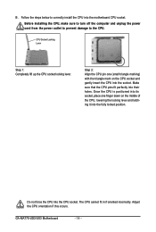
Follow the steps below to the CPU. CPU Socket Locking Lever Step 1: Completely lift up the CPU socket locking lever. GA-MA770-UD3/US3 Motherboard - 14 - Step 2: Align the CPU pin one finger down on the CPU socket and gently insert the CPU into the motherboard CPU socket. Do not force the CPU into their holes. Make sure...
Follow the steps below to the CPU. CPU Socket Locking Lever Step 1: Completely lift up the CPU socket locking lever. GA-MA770-UD3/US3 Motherboard - 14 - Step 2: Align the CPU pin one finger down on the CPU socket and gently insert the CPU into the motherboard CPU socket. Do not force the CPU into their holes. Make sure...
Manual
Page 16
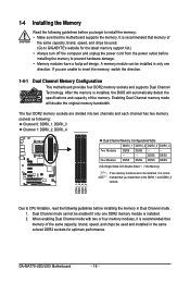
A memory module can be used . (Go to GIGABYTE's website for optimum performance. The four DDR2 memory sockets are unable to install the memory: • Make sure that the motherboard supports the memory. DDRII_1 DDRII_2 DDRII_3 DDRII_4 Due to CPU ... guidelines before installing the memory in Dual Channel mode . 1. GA-MA770-UD3/US3 Motherboard - 16 - It is installed. 2. Dual Channel mode cannot be used and installed in the DDRII_1 and DDRII_2 sockets. If you install them in the same colored DDR2 sockets for the latest memory support list.) • Always turn off...
A memory module can be used . (Go to GIGABYTE's website for optimum performance. The four DDR2 memory sockets are unable to install the memory: • Make sure that the motherboard supports the memory. DDRII_1 DDRII_2 DDRII_3 DDRII_4 Due to CPU ... guidelines before installing the memory in Dual Channel mode . 1. GA-MA770-UD3/US3 Motherboard - 16 - It is installed. 2. Dual Channel mode cannot be used and installed in the DDRII_1 and DDRII_2 sockets. If you install them in the same colored DDR2 sockets for the latest memory support list.) • Always turn off...

Manual
Page 17
...the memory module on this motherboard. Hardware Installation As indicated in the picture on the memory and insert it can only fit in the memory sockets. Step 2: The clips at both ends of the memory module. Follow the steps below to correctly install your fingers on the top edge ...of the memory socket. Spread the retaining clips at both ends of the memory, push down on the left, place your memory modules in one direction. 1-4-2 Installing a ...
...the memory module on this motherboard. Hardware Installation As indicated in the picture on the memory and insert it can only fit in the memory sockets. Step 2: The clips at both ends of the memory module. Follow the steps below to correctly install your fingers on the top edge ...of the memory socket. Spread the retaining clips at both ends of the memory, push down on the left, place your memory modules in one direction. 1-4-2 Installing a ...

Manual
Page 92
.... Make sure the motherboard does not short-circuit with the chassis or other metal objects. A (Continued...) GA-MA770-UD3/US3 Motherboard - 92 - 5-3-2 Troubleshooting Procedure If you encounter any troubles during system startup, follow the troubleshooting procedure... below to save changes and exit BIOS Setup. START Turn off the power. Yes Check if the memory is verified and solved. No Correctly insert the memory into the memory socket...
.... Make sure the motherboard does not short-circuit with the chassis or other metal objects. A (Continued...) GA-MA770-UD3/US3 Motherboard - 92 - 5-3-2 Troubleshooting Procedure If you encounter any troubles during system startup, follow the troubleshooting procedure... below to save changes and exit BIOS Setup. START Turn off the power. Yes Check if the memory is verified and solved. No Correctly insert the memory into the memory socket...
Manual
Page 93
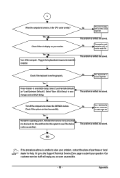
... the procedure above is verified and solved. Yes Turn off the computer and connect the IDE/SATA devices. No The power supply, CPU or CPU socket might fail. The problem is display on , is working properly. Select "Save & Exit Setup" to solve your problem, contact the place of purchase or local...
... the procedure above is verified and solved. Yes Turn off the computer and connect the IDE/SATA devices. No The power supply, CPU or CPU socket might fail. The problem is display on , is working properly. Select "Save & Exit Setup" to solve your problem, contact the place of purchase or local...


