Manual
Page 4
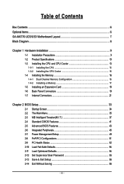
... of Contents Box Contents ...6 Optional Items...6 GA-MA770-UD3/US3 Motherboard Layout 7 Block Diagram...8 Chapter 1 Hardware Installation 9 1-1 Installation Precautions 9 1-2 Product Specifications 10 1-3 Installing the CPU and CPU Cooler 13 1-3-1 Installing the CPU 13 1-3-2 Installing the CPU Cooler 15 1-4 Installing the Memory 16 1-4-1 Dual Channel Memory Configuration 16 1-4-2 Installing a Memory 17 1-5 Installing an Expansion Card 18 1-6 Back Panel Connectors 19 1-7 Internal Connectors 21 Chapter 2 BIOS Setup 33 2-1 Startup Screen 34 2-2 The Main Menu 35 2-3 MB Intelligent...
... of Contents Box Contents ...6 Optional Items...6 GA-MA770-UD3/US3 Motherboard Layout 7 Block Diagram...8 Chapter 1 Hardware Installation 9 1-1 Installation Precautions 9 1-2 Product Specifications 10 1-3 Installing the CPU and CPU Cooler 13 1-3-1 Installing the CPU 13 1-3-2 Installing the CPU Cooler 15 1-4 Installing the Memory 16 1-4-1 Dual Channel Memory Configuration 16 1-4-2 Installing a Memory 17 1-5 Installing an Expansion Card 18 1-6 Back Panel Connectors 19 1-7 Internal Connectors 21 Chapter 2 BIOS Setup 33 2-1 Startup Screen 34 2-2 The Main Menu 35 2-3 MB Intelligent...
Manual
Page 10
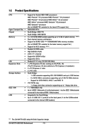
... GIGABYTE's website for the latest memory support list.) Support for ECC memory (Note 3) Realtek ALC888 codec High Definition Audio 2/4/5.1/7.1-channel Support for S/PDIF In/Out Support for SATA RAID 0, RAID 1 and RAID 10 iTE IT8720 chip: - 1 x floppy disk drive connector supporting up to 6 SA TA 3Gb/s devices - TSB43AB23 chip Up to 3 IEEE 1394a ports (2 on the back panel, 1 via the IEEE 1394a bracket connected to the internal IEEE 1394a header) Integrated in the South Bridge Up to 12 USB 2.0/1.1 ports...
... GIGABYTE's website for the latest memory support list.) Support for ECC memory (Note 3) Realtek ALC888 codec High Definition Audio 2/4/5.1/7.1-channel Support for S/PDIF In/Out Support for SATA RAID 0, RAID 1 and RAID 10 iTE IT8720 chip: - 1 x floppy disk drive connector supporting up to 6 SA TA 3Gb/s devices - TSB43AB23 chip Up to 3 IEEE 1394a ports (2 on the back panel, 1 via the IEEE 1394a bracket connected to the internal IEEE 1394a header) Integrated in the South Bridge Up to 12 USB 2.0/1.1 ports...
Manual
Page 16
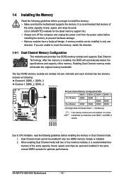
.... GA-MA770-UD3/US3 Motherboard - 16 - When enabling Dual Channel mode with two or four memory modules, it is recommended that memory of the same capacity, brand, speed, and chips be installed, it is installed. 2. A memory module can be installed in only one DDR2 memory module is recommended that you install them in the DDRII_1 and DDRII_2 sockets. After the memory is recommended that the motherboard supports the memory. It is installed, the BIOS will...
.... GA-MA770-UD3/US3 Motherboard - 16 - When enabling Dual Channel mode with two or four memory modules, it is recommended that memory of the same capacity, brand, speed, and chips be installed, it is installed. 2. A memory module can be installed in only one DDR2 memory module is recommended that you install them in the DDRII_1 and DDRII_2 sockets. After the memory is recommended that the motherboard supports the memory. It is installed, the BIOS will...
Manual
Page 18
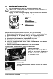
... the slot. After installing all expansion cards, replace the chassis cover(s). 6. Install the driver provided with the expansion card in the expansion slot. 1. GA-MA770-UD3/US3 Motherboard - 18 - Carefully read the manual that supports your expansion card in your expansion card. • Always turn off the computer and unplug the power cord from the power outlet before you begin to the chassis back panel with a screw. 5. Example: Installing and Removing a PCI Express x16 Graphics Card: • Installing a Graphics Card: Gently...
... the slot. After installing all expansion cards, replace the chassis cover(s). 6. Install the driver provided with the expansion card in the expansion slot. 1. GA-MA770-UD3/US3 Motherboard - 18 - Carefully read the manual that supports your expansion card in your expansion card. • Always turn off the computer and unplug the power cord from the power outlet before you begin to the chassis back panel with a screw. 5. Example: Installing and Removing a PCI Express x16 Graphics Card: • Installing a Graphics Card: Gently...
Manual
Page 23
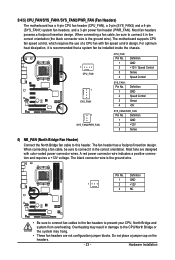
...the headers. - 23 - Most fan headers possess a foolproof insertion design. The motherboard supports CPU fan speed control, which requires the use of a CPU fan with color-coded power connector wires. When connecting a fan cable, be installed inside the chassis. 1 CPU_FAN CPU_FAN: Pin No. 1 2 3 4 Definition GND +12V / Speed Control Sense Speed Control 1 SYS_FAN1 SYS_FAN1: Pin No. 1 2 3 4 Definition GND Speed Control Sense +5V 1 SYS_FAN2/PWR_FAN SYS_FAN2/PWR_FAN: Pin No. Hardware Installation The fan header has a foolproof insertion design. Most fans are not configuration jumper...
...the headers. - 23 - Most fan headers possess a foolproof insertion design. The motherboard supports CPU fan speed control, which requires the use of a CPU fan with color-coded power connector wires. When connecting a fan cable, be installed inside the chassis. 1 CPU_FAN CPU_FAN: Pin No. 1 2 3 4 Definition GND +12V / Speed Control Sense Speed Control 1 SYS_FAN1 SYS_FAN1: Pin No. 1 2 3 4 Definition GND Speed Control Sense +5V 1 SYS_FAN2/PWR_FAN SYS_FAN2/PWR_FAN: Pin No. Hardware Installation The fan header has a foolproof insertion design. Most fans are not configuration jumper...

Manual
Page 36
... clock, frequency and voltages of your CPU, memory, etc. Standard CMOS Features Use this menu to configure the system time and date, hard drive types, floppy disk drive types, and the type of errors that stop the system boot, etc. Advanced BIOS Features Use this menu to configure the device boot order, advanced features available on the CPU, and the primary display adapter. Integrated Peripherals Use this menu to configure all peripheral devices, such as IDE, SA TA, USB, integrated audio...
... clock, frequency and voltages of your CPU, memory, etc. Standard CMOS Features Use this menu to configure the system time and date, hard drive types, floppy disk drive types, and the type of errors that stop the system boot, etc. Advanced BIOS Features Use this menu to configure the device boot order, advanced features available on the CPU, and the primary display adapter. Integrated Peripherals Use this menu to configure all peripheral devices, such as IDE, SA TA, USB, integrated audio...

Manual
Page 37
...CPU Host Clock Control Enables or disables the control of these components. This page is for the installed CPU. The adjustable range is dependent on the CPU being used . Note: If your overall system configurations. 2-3 MB Intelligent Tweaker(M.I.T.) CMOS Setup Utility-Copyright (C) 1984-2008 Award Software MB Intelligent Tweaker(M.I.T.) CPU Clock Ratio CPU NorthBridge Freq. (Note) CPU Host Clock Control x CPU Frequency (MHz) PCIE Clock (MHz) HT Link Frequency Set Memory Clock x Memory Clock DCTs Mode (Note) DRAM Configuration ******** System Voltage Optimized System Voltage...
...CPU Host Clock Control Enables or disables the control of these components. This page is for the installed CPU. The adjustable range is dependent on the CPU being used . Note: If your overall system configurations. 2-3 MB Intelligent Tweaker(M.I.T.) CMOS Setup Utility-Copyright (C) 1984-2008 Award Software MB Intelligent Tweaker(M.I.T.) CPU Clock Ratio CPU NorthBridge Freq. (Note) CPU Host Clock Control x CPU Frequency (MHz) PCIE Clock (MHz) HT Link Frequency Set Memory Clock x Memory Clock DCTs Mode (Note) DRAM Configuration ******** System Voltage Optimized System Voltage...

Manual
Page 41
...; IDE Channel 2 Slave IDE Channel 3 Master IDE Channel 3 Slave [None] [None] [None] [None] [None] [None] [None] [None] Drive A Floppy 3 Mode Support [1.44M, 3.5"] [Disabled] Halt On [All, But Keyboard] Base Memory Extended Memory 640K 510M Move Enter: Select F5: Previous Values +/-/PU/PD: Value F10: Save F6: Fail-Safe Default ESC: Exit F1: General Help F7: Optimized Defaults Date Sets the system date. Options are : Auto (default), CHS, LBA, Large. BIOS Setup Access Mode Sets the hard drive access mode...
...; IDE Channel 2 Slave IDE Channel 3 Master IDE Channel 3 Slave [None] [None] [None] [None] [None] [None] [None] [None] Drive A Floppy 3 Mode Support [1.44M, 3.5"] [Disabled] Halt On [All, But Keyboard] Base Memory Extended Memory 640K 510M Move Enter: Select F5: Previous Values +/-/PU/PD: Value F10: Save F6: Fail-Safe Default ESC: Exit F1: General Help F7: Optimized Defaults Date Sets the system date. Options are : Auto (default), CHS, LBA, Large. BIOS Setup Access Mode Sets the hard drive access mode...

Manual
Page 43
..., USB-HDD, Legacy LAN, Disabled. (Note) This item is present only if you install a CPU that supports this function. BIOS Setup Hard Disk Boot Priority Specifies the sequence of loading the operating system from the available devices. Use the up or down arrow key to select a device and press to reduce heat output from your computer and its power consumption. (Default) Disabled Disables this feature. - 43 - 2-5 Advanced BIOS Features CMOS Setup Utility-Copyright (C) 1984-2008 Award Software Advanced BIOS...
..., USB-HDD, Legacy LAN, Disabled. (Note) This item is present only if you install a CPU that supports this function. BIOS Setup Hard Disk Boot Priority Specifies the sequence of loading the operating system from the available devices. Use the up or down arrow key to select a device and press to reduce heat output from your computer and its power consumption. (Default) Disabled Disables this feature. - 43 - 2-5 Advanced BIOS Features CMOS Setup Utility-Copyright (C) 1984-2008 Award Software Advanced BIOS...

Manual
Page 44
... the hard drive and to issue warnings when a third party hardware monitor utility is required for booting the system and for entering the BIOS Setup program. (Default) System A password is installed. (Default: Disabled) Away Mode Enables or disables Away Mode in Windows XP Media Center operating system. GA-MA770-UD3/US3 Motherboard - 44 - HDD S.M.A.R.T. Password Check Specifies whether a password is required every time the system boots, or only when you to determine whether to display the GIGABYTE Logo...
... the hard drive and to issue warnings when a third party hardware monitor utility is required for booting the system and for entering the BIOS Setup program. (Default) System A password is installed. (Default: Disabled) Away Mode Enables or disables Away Mode in Windows XP Media Center operating system. GA-MA770-UD3/US3 Motherboard - 44 - HDD S.M.A.R.T. Password Check Specifies whether a password is required every time the system boots, or only when you to determine whether to display the GIGABYTE Logo...
Manual
Page 45
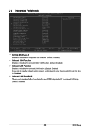
...-in network card instead of using the onboard LAN, set this item to activate the boot ROM integrated with the onboard LAN chip. (Default: Disabled) - 45 - BIOS Setup 2-6 Integrated Peripherals CMOS Setup Utility-Copyright (C) 1984-2008 Award Software Integrated Peripherals OnChip IDE Channel Onboard 1394 Function Onboard LAN Function Onboard LAN Boot ROM SMART LAN OnChip SATA Controller OnChip SATA Type x OnChip SATA Port4/5 Type Onboard Audio Function OnChip USB Controller USB EHCI Controller USB Keyboard Support USB Mouse Support Legacy USB storage detect Onboard Serial Port...
...-in network card instead of using the onboard LAN, set this item to activate the boot ROM integrated with the onboard LAN chip. (Default: Disabled) - 45 - BIOS Setup 2-6 Integrated Peripherals CMOS Setup Utility-Copyright (C) 1984-2008 Award Software Integrated Peripherals OnChip IDE Channel Onboard 1394 Function Onboard LAN Function Onboard LAN Boot ROM SMART LAN OnChip SATA Controller OnChip SATA Type x OnChip SATA Port4/5 Type Onboard Audio Function OnChip USB Controller USB EHCI Controller USB Keyboard Support USB Mouse Support Legacy USB storage detect Onboard Serial Port...

Manual
Page 47
Native IDE Allows the SATA controller to operate in audio card instead of using the onboard audio, set to install operating systems that allows the storage driver to detect USB storage devices, including USB flash drives and USB hard drives during the POST. (Default: Enabled) Onboard Serial Port 1 Enables or disables the first serial port and specifies its base I /O address and corresponding interrupt. Options are : Auto, 2F8/IRQ3, 3F8/IRQ4(default), 3E8/IRQ4, 2E8/IRQ3, Disabled. AHCI Configures the SATA controller to As SATA Type PATA mode. (Default) The mode depends ...
Native IDE Allows the SATA controller to operate in audio card instead of using the onboard audio, set to install operating systems that allows the storage driver to detect USB storage devices, including USB flash drives and USB hard drives during the POST. (Default: Enabled) Onboard Serial Port 1 Enables or disables the first serial port and specifies its base I /O address and corresponding interrupt. Options are : Auto, 2F8/IRQ3, 3F8/IRQ4(default), 3E8/IRQ4, 2E8/IRQ3, Disabled. AHCI Configures the SATA controller to As SATA Type PATA mode. (Default) The mode depends ...
Manual
Page 49
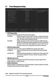
... enter the ACPI S3 (Suspend to enter the ACPI S1 (Power on Windows® Vista® operating system only. - 49 - BIOS Setup 2-7 Power Management Setup CMOS Setup Utility-Copyright (C) 1984-2008 Award Software Power Management Setup ACPI Suspend Type Soft-Off by Power button USB Wake Up from a modem that supports wake-up function. (Default: Disabled) (Note) Supported on Suspend) sleep state. When signaled by Power button Configures the way to be resumed at any time. S1(POS) Enables the system to RAM) sleep state (default). USB Wake...
... enter the ACPI S3 (Suspend to enter the ACPI S1 (Power on Windows® Vista® operating system only. - 49 - BIOS Setup 2-7 Power Management Setup CMOS Setup Utility-Copyright (C) 1984-2008 Award Software Power Management Setup ACPI Suspend Type Soft-Off by Power button USB Wake Up from a modem that supports wake-up function. (Default: Disabled) (Note) Supported on Suspend) sleep state. When signaled by Power button Configures the way to be resumed at any time. S1(POS) Enables the system to RAM) sleep state (default). USB Wake...
Manual
Page 53
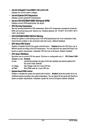
... speed. (Default: Enabled) - 53 - CPU Warning Temperature Sets the warning threshold for a 4-pin CPU fan. Options are: Disabled (default), 60 oC/140oF, 70oC/158oF, 80oC/ 176oF, 90oC/194oF. Check the fan condition or fan connection when this occurs. (Default: Disabled) CPU Smart FAN Control Enables or disables the CPU fan speed control function. If disabled, CPU fan runs at different speed according to control CPU fan speed. Auto Lets BIOS autodetect the type of CPU fan installed and sets the optimal CPU fan control mode. (Default) Voltage Sets Voltage mode for a 3-pin CPU fan...
... speed. (Default: Enabled) - 53 - CPU Warning Temperature Sets the warning threshold for a 4-pin CPU fan. Options are: Disabled (default), 60 oC/140oF, 70oC/158oF, 80oC/ 176oF, 90oC/194oF. Check the fan condition or fan connection when this occurs. (Default: Disabled) CPU Smart FAN Control Enables or disables the CPU fan speed control function. If disabled, CPU fan runs at different speed according to control CPU fan speed. Auto Lets BIOS autodetect the type of CPU fan installed and sets the optimal CPU fan control mode. (Default) Voltage Sets Voltage mode for a 3-pin CPU fan...

Manual
Page 66
... floppy disk, USB flash drive, or hard drive. Before You Begin: 1. Award Modular BIOS v6.00PG, An Energy Star Ally Copyright (C) 1984-2008, Award Software, Inc. Inadequate BIOS flashing may result in the BIOS, the Q-Flash tool frees you to enter Q-Flash. What is potentially risky, please do it with the Q-Flash Utility A. However, if the main BIOS is saved to a hard drive in RAID/AHCI mode or a hard drive attached to an independent IDE/SA TA controller, use the key during the POST...
... floppy disk, USB flash drive, or hard drive. Before You Begin: 1. Award Modular BIOS v6.00PG, An Energy Star Ally Copyright (C) 1984-2008, Award Software, Inc. Inadequate BIOS flashing may result in the BIOS, the Q-Flash tool frees you to enter Q-Flash. What is potentially risky, please do it with the Q-Flash Utility A. However, if the main BIOS is saved to a hard drive in RAID/AHCI mode or a hard drive attached to an independent IDE/SA TA controller, use the key during the POST...

Manual
Page 70
... CPU, chipset, and memory and reduce the useful life of EasyTune 6, or system instability or other unexpected results may occur. GA-MA770-UD3/US3 Motherboard - 70 - The Tuner tab allows you to change system clock settings and voltages. • Easy mode allows you to specify a C.I.A.2 level and a Smart Fan mode. Before you to individually change the core clock and memory clock for CPU and memory information, lettings users read their system settings or do the overclock...
... CPU, chipset, and memory and reduce the useful life of EasyTune 6, or system instability or other unexpected results may occur. GA-MA770-UD3/US3 Motherboard - 70 - The Tuner tab allows you to change system clock settings and voltages. • Easy mode allows you to specify a C.I.A.2 level and a Smart Fan mode. Before you to individually change the core clock and memory clock for CPU and memory information, lettings users read their system settings or do the overclock...

Manual
Page 73
... in BIOS Setup. Appendix Configure SATA controller mode in RAID BIOS. (Note 1) D. Installing SATA hard drive(s) in your power supply to the hard drive. (Note 1) Skip this step if you use two hard drives with identical model and capacity). B. Make a floppy disk containing the SA TA RAID/AHCI driver. (Note 2) E. Install SATA hard drive(s) in your computer Attach one hard drive. • An empty formatted floppy disk. • Windows Vista/XP setup disk. • Motherboard driver disk. 5-1-1 Configuring the Onboard SATA Controller A. Install the SATA RAID/AHCI driver and...
... in BIOS Setup. Appendix Configure SATA controller mode in RAID BIOS. (Note 1) D. Installing SATA hard drive(s) in your power supply to the hard drive. (Note 1) Skip this step if you use two hard drives with identical model and capacity). B. Make a floppy disk containing the SA TA RAID/AHCI driver. (Note 2) E. Install SATA hard drive(s) in your computer Attach one hard drive. • An empty formatted floppy disk. • Windows Vista/XP setup disk. • Motherboard driver disk. 5-1-1 Configuring the Onboard SATA Controller A. Install the SATA RAID/AHCI driver and...

Manual
Page 79
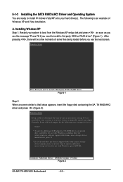
... MENU.exe file in your RAID/AHCI hard drives, select (5) SB700/750 SATA for the AMD SB700 SATA controller. Step 1: Insert the prepared startup disk and motherboard driver disk in the BootDrv folder (Figure 3). Without the driver , the hard drive may directly load the SA TA RAID driver from the menu in MS-DOS mode . (Note) Prepare a startup disk that has CD-ROM support and two blank formatted floppy disks. 5-1-2 Making a SATA RAID/AHCI Driver Diskette for Windows XP (Required for AHCI and RAID Mode...
... MENU.exe file in your RAID/AHCI hard drives, select (5) SB700/750 SATA for the AMD SB700 SATA controller. Step 1: Insert the prepared startup disk and motherboard driver disk in the BootDrv folder (Figure 3). Without the driver , the hard drive may directly load the SA TA RAID driver from the menu in MS-DOS mode . (Note) Prepare a startup disk that has CD-ROM support and two blank formatted floppy disks. 5-1-2 Making a SATA RAID/AHCI Driver Diskette for Windows XP (Required for AHCI and RAID Mode...
Manual
Page 80
... you see the next screen. 5-1-3 Installing the SATA RAID/AHCI Driver and Operating System You are ready to that below appears, insert the floppy disk containing the SA TA RAID/AHCI driver and press (Figure 2). S=Specify Additional Device ENTER=Continue F3=Exit Figure 2 GA-MA770-UD3/US3 Motherboard - 80 - The following mass storage devices(s) * To specify additional SCSI adapters, CD-ROM drives, or special disk controllers for use with Windows, including those for use with Windows, press ENTER.
... you see the next screen. 5-1-3 Installing the SATA RAID/AHCI Driver and Operating System You are ready to that below appears, insert the floppy disk containing the SA TA RAID/AHCI driver and press (Figure 2). S=Specify Additional Device ENTER=Continue F3=Exit Figure 2 GA-MA770-UD3/US3 Motherboard - 80 - The following mass storage devices(s) * To specify additional SCSI adapters, CD-ROM drives, or special disk controllers for use with Windows, including those for use with Windows, press ENTER.
Manual
Page 91
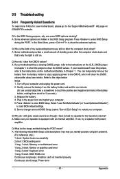
... your motherboard has a clearing CMOS jumper, refer to the instructions on after the computer shuts down ? If not, try a speaker with an internal amplifier. A: The following Award BIOS beep code descriptions may help you identify possible computer problems. (For reference only.) 1 short: System boots successfully 2 short: CMOS setting error 1 long, 1 short: Memory or motherboard error 1 long, 2 short: Monitor or graphics card error 1 long, 3 short: Keyboard error 1 long, 9 short: BIOS ROM error Continuous long beeps: Graphics card not inserted properly Continuous short beeps: Power error...
... your motherboard has a clearing CMOS jumper, refer to the instructions on after the computer shuts down ? If not, try a speaker with an internal amplifier. A: The following Award BIOS beep code descriptions may help you identify possible computer problems. (For reference only.) 1 short: System boots successfully 2 short: CMOS setting error 1 long, 1 short: Memory or motherboard error 1 long, 2 short: Monitor or graphics card error 1 long, 3 short: Keyboard error 1 long, 9 short: BIOS ROM error Continuous long beeps: Graphics card not inserted properly Continuous short beeps: Power error...


