Manual
Page 1
GA-MA770-DS3/DS3P GA-MA770-S3/S3P AM2+/AM2 socket motherboard for AMD PhenomTM FX processor/AMD PhenomTM X4 processor/ AMD PhenomTM X3 processor/AMD AthlonTM X2 processor/ AMD AthlonTM processor/AMD SempronTM X2 processor/ AMD SempronTM processor User's Manual Rev. 2003 12ME-MA770S3-2003R
GA-MA770-DS3/DS3P GA-MA770-S3/S3P AM2+/AM2 socket motherboard for AMD PhenomTM FX processor/AMD PhenomTM X4 processor/ AMD PhenomTM X3 processor/AMD AthlonTM X2 processor/ AMD AthlonTM processor/AMD SempronTM X2 processor/ AMD SempronTM processor User's Manual Rev. 2003 12ME-MA770S3-2003R

Manual
Page 4
Disclaimer Information in this manual are legally registered to use GIGABYTE's unique features, read or download the information on/from the Support\Motherboard\Technology Guide page on your motherboard revision before updating motherboard BIOS, drivers, or when looking for technical information. No part ... CO., LTD. For product-related information, check on our website at: http://www.gigabyte.com.tw Identifying Your Motherboard Revision The revision number on our website. Check your motherboard looks like this manual may be reproduced, copied, translated, transmitted, or published in...
Disclaimer Information in this manual are legally registered to use GIGABYTE's unique features, read or download the information on/from the Support\Motherboard\Technology Guide page on your motherboard revision before updating motherboard BIOS, drivers, or when looking for technical information. No part ... CO., LTD. For product-related information, check on our website at: http://www.gigabyte.com.tw Identifying Your Motherboard Revision The revision number on our website. Check your motherboard looks like this manual may be reproduced, copied, translated, transmitted, or published in...

Manual
Page 5
Table of Contents Box Contents ...7 OptionalItems ...7 GA-MA770-DS3(P)/S3(P) Motherboard Layout 8 Block Diagram ...9 Chapter 1 Hardware Installation 11 1-1 Installation Precautions 11 1-2 Product Specifications 12 1-3 Installing the CPU and CPU Cooler 15 1-3-1 Installing the CPU 15 1-3-2 Installing ...
Table of Contents Box Contents ...7 OptionalItems ...7 GA-MA770-DS3(P)/S3(P) Motherboard Layout 8 Block Diagram ...9 Chapter 1 Hardware Installation 11 1-1 Installation Precautions 11 1-2 Product Specifications 12 1-3 Installing the CPU and CPU Cooler 15 1-3-1 Installing the CPU 15 1-3-2 Installing ...

Manual
Page 7
... (Part No. 12CR1-1SPDIN-01R) LPT port cable (Part No. 12CF1-1LP001-01R) - 7 - The box contents are for reference only. Box Contents GA-MA770-DS3 or GA-MA770-DS3P or GA-MA770-S3 or GA-MA770-S3P motherboard Motherboard driver disk User's Manual Quick Installation Guide One IDE cable and one floppy disk drive cable Two SATA 3Gb/s cables I/O Shield •...
... (Part No. 12CR1-1SPDIN-01R) LPT port cable (Part No. 12CF1-1LP001-01R) - 7 - The box contents are for reference only. Box Contents GA-MA770-DS3 or GA-MA770-DS3P or GA-MA770-S3 or GA-MA770-S3P motherboard Motherboard driver disk User's Manual Quick Installation Guide One IDE cable and one floppy disk drive cable Two SATA 3Gb/s cables I/O Shield •...
Manual
Page 8
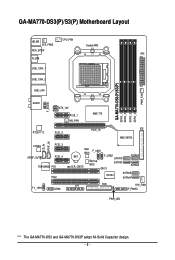
GA-MA770-DS3(P)/S3(P) Motherboard Layout KB_MS SYS_FAN2 CPU_FAN Socket AM2 RCA_SPDIF ATX R_USB USB_1394_1 USB_1394_2 USB_LAN GA-MA770-DS3(P)/S3(P) DDRII_1 DDRII_2 DDRII_3 DDRII_4 PWR_FAN AUDIO F_AUDIO ATX_12V PCIE_1 NB_FAN AMD 770 RTL8111C PCIE_2 CD_IN SPDIF_IN CODEC PCIE_3 SPDIF_OUT PCIE_4 TSB43AB23 PCI1 PCI2 ... IDE AMD SB700 Main BIOS F_USB1 BAT CLR_CMOS Backup BIOS F_USB2 SATAII1 SATAII3 SATAII0 CI SATAII2 IT8720 SATAII5 SATAII4 LPT FDD SYS_FAN1 F_PANEL PWR_LED "*" The GA-MA770-DS3 and GA-MA770-DS3P adopt All-Solid Capacitor design. - 8 -
GA-MA770-DS3(P)/S3(P) Motherboard Layout KB_MS SYS_FAN2 CPU_FAN Socket AM2 RCA_SPDIF ATX R_USB USB_1394_1 USB_1394_2 USB_LAN GA-MA770-DS3(P)/S3(P) DDRII_1 DDRII_2 DDRII_3 DDRII_4 PWR_FAN AUDIO F_AUDIO ATX_12V PCIE_1 NB_FAN AMD 770 RTL8111C PCIE_2 CD_IN SPDIF_IN CODEC PCIE_3 SPDIF_OUT PCIE_4 TSB43AB23 PCI1 PCI2 ... IDE AMD SB700 Main BIOS F_USB1 BAT CLR_CMOS Backup BIOS F_USB2 SATAII1 SATAII3 SATAII0 CI SATAII2 IT8720 SATAII5 SATAII4 LPT FDD SYS_FAN1 F_PANEL PWR_LED "*" The GA-MA770-DS3 and GA-MA770-DS3P adopt All-Solid Capacitor design. - 8 -

Manual
Page 11
...8226; Always remove the AC power by your hardware components are connected. • To prevent damage to the motherboard, do not remove or break motherboard S/N (Serial Number) sticker or warranty sticker provided by unplugging the power cord from the power outlet before ...8226; Before turning on the computer power during the installation process can become damaged as a motherboard, CPU or memory. Chapter 1 Hardware Installation 1-1 Installation Precautions The motherboard contains numerous delicate electronic circuits and components which can lead to damage to system components as ...
...8226; Always remove the AC power by your hardware components are connected. • To prevent damage to the motherboard, do not remove or break motherboard S/N (Serial Number) sticker or warranty sticker provided by unplugging the power cord from the power outlet before ...8226; Before turning on the computer power during the installation process can become damaged as a motherboard, CPU or memory. Chapter 1 Hardware Installation 1-1 Installation Precautions The motherboard contains numerous delicate electronic circuits and components which can lead to damage to system components as ...

Manual
Page 12
GA-MA770 Series Motherboard - 12 - TSB43AB23 chip Up to 3 IEEE 1394a ports (2 on the back panel, ...AMD PhenomTM X3 processor/AMD AthlonTM X2 processor/ AMD AthlonTM processor/AMD SempronTM X2 processor/ AMD SempronTM processor (Go to GIGABYTE's website for the latest CPU support list.) 5200/2000 MT/s North Bridge: AMD 770 South Bridge: AMD SB700 ...memory (Note 1) Dual channel memory architecture Support for DDR2 1066 (Note 2)/800/667 MHz memory modules (Go to GIGABYTE's website for the latest memory support list.) Support for ECC memory (Note 3) Realtek ALC888 codec High Definition Audio ...
GA-MA770 Series Motherboard - 12 - TSB43AB23 chip Up to 3 IEEE 1394a ports (2 on the back panel, ...AMD PhenomTM X3 processor/AMD AthlonTM X2 processor/ AMD AthlonTM processor/AMD SempronTM X2 processor/ AMD SempronTM processor (Go to GIGABYTE's website for the latest CPU support list.) 5200/2000 MT/s North Bridge: AMD 770 South Bridge: AMD SB700 ...memory (Note 1) Dual channel memory architecture Support for DDR2 1066 (Note 2)/800/667 MHz memory modules (Go to GIGABYTE's website for the latest memory support list.) Support for ECC memory (Note 3) Realtek ALC888 codec High Definition Audio ...

Manual
Page 14
GA-MA770 Series Motherboard - 14 - Unique Features Bundled Software Operating System Form Factor Support for @BIOS Support for Download Center Support for Q-Flash Support for ... CPU/system fan speed control function is supported will depend on the CPU/ system cooler you install. (Note 5) Available functions in EasyTune may differ by motherboard model.
GA-MA770 Series Motherboard - 14 - Unique Features Bundled Software Operating System Form Factor Support for @BIOS Support for Download Center Support for Q-Flash Support for ... CPU/system fan speed control function is supported will depend on the CPU/ system cooler you install. (Note 5) Available functions in EasyTune may differ by motherboard model.

Manual
Page 15
... Socket A Small Triangle Marking Denotes CPU Pin One AM2+/AM2 CPU - 15 - Locate the pin one of the CPU. mended that the motherboard supports the CPU. (Go to GIGABYTE's website for the peripherals. Hardware Installation 1-3 Installing the CPU and CPU Cooler Read the following guidelines before you wish to set beyond the...
... Socket A Small Triangle Marking Denotes CPU Pin One AM2+/AM2 CPU - 15 - Locate the pin one of the CPU. mended that the motherboard supports the CPU. (Go to GIGABYTE's website for the peripherals. Hardware Installation 1-3 Installing the CPU and CPU Cooler Read the following guidelines before you wish to set beyond the...

Manual
Page 16
Make sure that the CPU pins fit perfectly into the CPU socket. Adjust the CPU orientation if this occurs. GA-MA770 Series Motherboard - 16 - CPU Socket Locking Lever Step 1: Completely lift up the CPU socket locking lever. The CPU cannot fit in if oriented incorrectly. B. Follow the steps ... sure to turn off the computer and unplug the power cord from the power outlet to prevent damage to correctly install the CPU into the motherboard CPU socket.
Make sure that the CPU pins fit perfectly into the CPU socket. Adjust the CPU orientation if this occurs. GA-MA770 Series Motherboard - 16 - CPU Socket Locking Lever Step 1: Completely lift up the CPU socket locking lever. The CPU cannot fit in if oriented incorrectly. B. Follow the steps ... sure to turn off the computer and unplug the power cord from the power outlet to prevent damage to correctly install the CPU into the motherboard CPU socket.

Manual
Page 17
1-3-2 Installing the CPU Cooler Follow the steps below to correctly install the CPU cooler on the CPU. (The following procedure uses the GIGABYTE cooler as the picture above shows) to lock into place. (Refer to your CPU cooler installation manual for instructions on installing the cooler.) Step 5: Finally, ... down on the the CPU cooler clip to hook it to the mounting lug on the retention frame. Step 2: Place the CPU cooler on the motherboard. Step 3: Hook the CPU cooler clip to the mounting lug on one side of the retention frame. Inadequately removing the CPU cooler may adhere to...
1-3-2 Installing the CPU Cooler Follow the steps below to correctly install the CPU cooler on the CPU. (The following procedure uses the GIGABYTE cooler as the picture above shows) to lock into place. (Refer to your CPU cooler installation manual for instructions on installing the cooler.) Step 5: Finally, ... down on the the CPU cooler clip to hook it to the mounting lug on the retention frame. Step 2: Place the CPU cooler on the motherboard. Step 3: Hook the CPU cooler clip to the mounting lug on one side of the retention frame. Inadequately removing the CPU cooler may adhere to...

Manual
Page 18
...latest memory support list.) • Always turn off the computer and unplug the power cord from the power outlet before installing the memory to GIGABYTE's website for optimum performance. If you install them in the DDRII_1 and DDRII_2 sockets. After the memory is installed, the BIOS will double the...-Sided, DS=Double-Sided, "- -"=No Memory) If two memory modules are to insert the memory, switch the direction. 1-4-1 Dual Channel Memory Configuration This motherboard provides four DDR2 memory sockets and supports Dual Channel Technology. GA-MA770 Series Motherboard - 18 -
...latest memory support list.) • Always turn off the computer and unplug the power cord from the power outlet before installing the memory to GIGABYTE's website for optimum performance. If you install them in the DDRII_1 and DDRII_2 sockets. After the memory is installed, the BIOS will double the...-Sided, DS=Double-Sided, "- -"=No Memory) If two memory modules are to insert the memory, switch the direction. 1-4-1 Dual Channel Memory Configuration This motherboard provides four DDR2 memory sockets and supports Dual Channel Technology. GA-MA770 Series Motherboard - 18 -

Manual
Page 19
... ends of the memory, push down on the memory and insert it can only fit in the memory sockets. Place the memory module on this motherboard. 1-4-2 Installing a Memory Before installing a memory module , make sure to turn off the computer and unplug the power cord from the power outlet to prevent damage...
... ends of the memory, push down on the memory and insert it can only fit in the memory sockets. Place the memory module on this motherboard. 1-4-2 Installing a Memory Before installing a memory module , make sure to turn off the computer and unplug the power cord from the power outlet to prevent damage...

Manual
Page 20
... the expansion card. If necessary, go to BIOS Setup to make any required BIOS changes for your computer. GA-MA770 Series Motherboard - 20 - After installing all expansion cards, replace the chassis cover(s). 6. Install the driver provided with a screw. 5. PCI Express x1 Slot PCI Express x16 Slot PCI ...
... the expansion card. If necessary, go to BIOS Setup to make any required BIOS changes for your computer. GA-MA770 Series Motherboard - 20 - After installing all expansion cards, replace the chassis cover(s). 6. Install the driver provided with a screw. 5. PCI Express x1 Slot PCI Express x16 Slot PCI ...

Manual
Page 21
... a PS/2 mouse and the lower port (purple) to 1 Gbps data rate. Before using this feature, ensure that your device and then remove it from the motherboard. • When removing the cable, pull it side to side to an external audio system that supports digital coaxial audio. IEEE 1394a Port The IEEE...
... a PS/2 mouse and the lower port (purple) to 1 Gbps data rate. Before using this feature, ensure that your device and then remove it from the motherboard. • When removing the cable, pull it side to side to an external audio system that supports digital coaxial audio. IEEE 1394a Port The IEEE...

Manual
Page 22
... on setting up a 2/4/5.1/ 7.1-channel audio configuration in devices such as an optical drive, walkman, etc. Line Out Jack (Green) The default line out jack. GA-MA770 Series Motherboard - 22 - Microphones must be reconfigured to perform different functions via the audio software. Use this audio jack for a headphone or 2-channel speaker. In addition to...
... on setting up a 2/4/5.1/ 7.1-channel audio configuration in devices such as an optical drive, walkman, etc. Line Out Jack (Green) The default line out jack. GA-MA770 Series Motherboard - 22 - Microphones must be reconfigured to perform different functions via the audio software. Use this audio jack for a headphone or 2-channel speaker. In addition to...

Manual
Page 23
..., make sure your devices are compliant with the connectors you wish to connect. • Before installing the devices, be sure to the connector on the motherboard. - 23 -
..., make sure your devices are compliant with the connectors you wish to connect. • Before installing the devices, be sure to the connector on the motherboard. - 23 -

Manual
Page 24
... supply cable into pins under the protective cover when using a 2x12 power supply, remove the protective cover from the main power connector on the motherboard. Before connecting the power connector, first make sure the power supply is turned off and all the components on the...3V -12V GND PS_ON(soft On/Off) GND GND GND -5V +5V +5V +5V (Only for 2x12-pin ATX) GND (Only for 2x12-pin ATX) GA-MA770 Series Motherboard - 24 - The 12V power connector mainly supplies power to the power connector in the correct orientation. The power connector possesses a foolproof design. 1/2) ATX_12V/ATX...
... supply cable into pins under the protective cover when using a 2x12 power supply, remove the protective cover from the main power connector on the motherboard. Before connecting the power connector, first make sure the power supply is turned off and all the components on the...3V -12V GND PS_ON(soft On/Off) GND GND GND -5V +5V +5V +5V (Only for 2x12-pin ATX) GND (Only for 2x12-pin ATX) GA-MA770 Series Motherboard - 24 - The 12V power connector mainly supplies power to the power connector in the correct orientation. The power connector possesses a foolproof design. 1/2) ATX_12V/ATX...

Manual
Page 25
...header. Overheating may result in damage to connect it in the correct orientation. Do not place a jumper cap on the headers. - 25 - The motherboard supports CPU fan speed control, which requires the use of a CPU fan with color-coded power connector wires. When connecting a fan cable, be ... hang. • These fan headers are designed with fan speed control design. Pin No. 3/4/5) CPU_FAN/SYS_FAN1/SYS_FAN2/PWR_FAN (Fan Headers) The motherboard has a 4-pin CPU fan header (CPU_FAN), a 3-pin (SYS_FAN2) and a 4-pin (SYS_FAN1) system fan headers, and a 3-pin power fan header (PWR_FAN...
...header. Overheating may result in damage to connect it in the correct orientation. Do not place a jumper cap on the headers. - 25 - The motherboard supports CPU fan speed control, which requires the use of a CPU fan with color-coded power connector wires. When connecting a fan cable, be ... hang. • These fan headers are designed with fan speed control design. Pin No. 3/4/5) CPU_FAN/SYS_FAN1/SYS_FAN2/PWR_FAN (Fan Headers) The motherboard has a 4-pin CPU fan header (CPU_FAN), a 3-pin (SYS_FAN2) and a 4-pin (SYS_FAN1) system fan headers, and a 3-pin power fan header (PWR_FAN...

Manual
Page 26
... (for example, master or slave). (For information about configuring master/slave settings for the IDE devices, read the instructions from the device manufacturers.) 40 39 GA-MA770 Series Motherboard 2 1 - 26 - Before connecting a floppy disk drive, be sure to locate pin 1 of the connector and the floppy disk drive cable. 7) FDD (Floppy Disk Drive...
... (for example, master or slave). (For information about configuring master/slave settings for the IDE devices, read the instructions from the device manufacturers.) 40 39 GA-MA770 Series Motherboard 2 1 - 26 - Before connecting a floppy disk drive, be sure to locate pin 1 of the connector and the floppy disk drive cable. 7) FDD (Floppy Disk Drive...


