
Manual
Page 4
Table of Contents Box Contents...6 Optional Items...6 GA-MA74GM-S2H/GA-MA74GM-S2 Motherboard Layout 7 Block Diagram...8 Chapter 1 Hardware Installation 9 1-1 Installation Precautions 9 1-2 Product Specifications 10 1-3 Installing the CPU and CPU Cooler 13 1-3-1 Installing the CPU 13 1-3-2 Installing the CPU Cooler 15 1-4 Installing the Memory 16 1-4-1 Dual Channel Memory Configuration 16 1-4-2 Installing a Memory 17 1-5 Installing an Expansion Card 18 1-6 Back...
Table of Contents Box Contents...6 Optional Items...6 GA-MA74GM-S2H/GA-MA74GM-S2 Motherboard Layout 7 Block Diagram...8 Chapter 1 Hardware Installation 9 1-1 Installation Precautions 9 1-2 Product Specifications 10 1-3 Installing the CPU and CPU Cooler 13 1-3-1 Installing the CPU 13 1-3-2 Installing the CPU Cooler 15 1-4 Installing the Memory 16 1-4-1 Dual Channel Memory Configuration 16 1-4-2 Installing a Memory 17 1-5 Installing an Expansion Card 18 1-6 Back...

Manual
Page 8
Block Diagram PCIe CLK (100 MHz) 1 PCI Express x16 AM3/AM2+/AM2 CPU CPU CLK+/- (200 MHz) DDR2 1066/800/667/533 MHz Dual Channel Memory Hyper Transport Bus PCI Express x16 GFX CLK (100 MHz) PCI Express Bus x1 PCIe CLK (100 MHz) 1 PCI Express x1 RTL8111D RJ45 LAN AMD ... BIOS Floppy COM Port 2 PCI PS/2 KB or Mouse MIC Line Out Line In S/PDIF In S/PDIF Out PCI CLK (33 MHz) j (Note) Only for GA-MA74GM-S2H Simultaneous output for DVI-D and HDMI is not supported. - 8 -
Block Diagram PCIe CLK (100 MHz) 1 PCI Express x16 AM3/AM2+/AM2 CPU CPU CLK+/- (200 MHz) DDR2 1066/800/667/533 MHz Dual Channel Memory Hyper Transport Bus PCI Express x16 GFX CLK (100 MHz) PCI Express Bus x1 PCIe CLK (100 MHz) 1 PCI Express x1 RTL8111D RJ45 LAN AMD ... BIOS Floppy COM Port 2 PCI PS/2 KB or Mouse MIC Line Out Line In S/PDIF In S/PDIF Out PCI CLK (33 MHz) j (Note) Only for GA-MA74GM-S2H Simultaneous output for DVI-D and HDMI is not supported. - 8 -

Manual
Page 9
... the motherboard, make sure they are required for warranty validation. • Always remove the AC power by your dealer. ponents such as a motherboard, CPU or memory.
... the motherboard, make sure they are required for warranty validation. • Always remove the AC power by your dealer. ponents such as a motherboard, CPU or memory.

Manual
Page 10
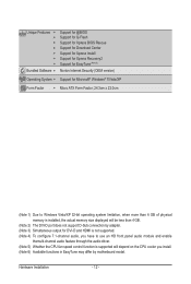
... and up to 2 IDE devices - 4 x SATA 3Gb/s connectors supporting up to 8 GB of system memory (Note 1) Dual channel memory architecture Support for DDR2 1066/800/667/533 MHz memory modules Support for non-ECC memory modules (Go to GIGABYTE's website for GA-MA74GM-S2H Hardware Installation - 10 - 1-2 Product Specifications CPU Support for AM3/AM2+/AM2 processors: AMD Phenom...
... and up to 2 IDE devices - 4 x SATA 3Gb/s connectors supporting up to 8 GB of system memory (Note 1) Dual channel memory architecture Support for DDR2 1066/800/667/533 MHz memory modules Support for non-ECC memory modules (Go to GIGABYTE's website for GA-MA74GM-S2H Hardware Installation - 10 - 1-2 Product Specifications CPU Support for AM3/AM2+/AM2 processors: AMD Phenom...
Manual
Page 12
... Form Factor; 24.3cm x 22.0cm (Note 1) Due to Windows Vista/XP 32-bit operating system limitation, when more than 4 GB of physical memory is installed, the actual memory size displayed will be less than 4 GB. (Note 2) The DVI-D port does not support D-Sub connection by adapter. (Note 3) Simultaneous output for DVI...
... Form Factor; 24.3cm x 22.0cm (Note 1) Due to Windows Vista/XP 32-bit operating system limitation, when more than 4 GB of physical memory is installed, the actual memory size displayed will be less than 4 GB. (Note 2) The DVI-D port does not support D-Sub connection by adapter. (Note 3) Simultaneous output for DVI...
Manual
Page 13
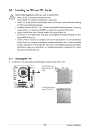
... even and thin layer of thermal grease on the computer if the CPU cooler is not recommended that the motherboard supports the CPU. (Go to GIGABYTE's website for the latest CPU support list.) • Always turn on the surface of the CPU. • Do not turn off the computer and unplug... the CPU specifications. If you wish to set beyond the standard specifications, please do so according to your hardware specifications including the CPU, graphics card, memory, hard drive, etc. 1-3-1 Installing the CPU A.
... even and thin layer of thermal grease on the computer if the CPU cooler is not recommended that the motherboard supports the CPU. (Go to GIGABYTE's website for the latest CPU support list.) • Always turn on the surface of the CPU. • Do not turn off the computer and unplug... the CPU specifications. If you wish to set beyond the standard specifications, please do so according to your hardware specifications including the CPU, graphics card, memory, hard drive, etc. 1-3-1 Installing the CPU A.
Manual
Page 16
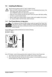
If you begin to install the memory: • Make sure that the motherboard supports the memory. Dual Channel mode cannot be enabled if only one DDR2 memory module is recommended that memory of the same capacity, brand, speed, and chips be used . (Go to GIGABYTE's website for the latest memory support list.) • Always turn off the...
If you begin to install the memory: • Make sure that the motherboard supports the memory. Dual Channel mode cannot be enabled if only one DDR2 memory module is recommended that memory of the same capacity, brand, speed, and chips be used . (Go to GIGABYTE's website for the latest memory support list.) • Always turn off the...

Manual
Page 17
...DDR DIMMs. Be sure to install DDR2 DIMMs on the socket. Follow the steps below to the memory module. Step 2: The clips at both ends of the memory module. 1-4-2 Installing a Memory Before installing a memory module , make sure to turn off the computer and unplug the power cord from the power ...outlet to prevent damage to correctly install your fingers on the top edge of the memory socket. Notch DDR2 DIMM A DDR2 memory module has a notch, so it vertically into place when the memory module is securely inserted. - 17 - Spread the retaining clips at both ends of the...
...DDR DIMMs. Be sure to install DDR2 DIMMs on the socket. Follow the steps below to the memory module. Step 2: The clips at both ends of the memory module. 1-4-2 Installing a Memory Before installing a memory module , make sure to turn off the computer and unplug the power cord from the power ...outlet to prevent damage to correctly install your fingers on the top edge of the memory socket. Notch DDR2 DIMM A DDR2 memory module has a notch, so it vertically into place when the memory module is securely inserted. - 17 - Spread the retaining clips at both ends of the...
Manual
Page 20
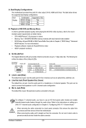
...: This motherboard provides three ports for line in jack. The table below . • CPU: AMD Phenom™ X3 processor or above • Memory: Two 1 GB DDR2 800 MHz memory modules with dual channel mode enabled • BIOS Setup: At least 256 MB of UMA Frame Buffer Size (refer to Chapter 2, "BIOS Setup...
...: This motherboard provides three ports for line in jack. The table below . • CPU: AMD Phenom™ X3 processor or above • Memory: Two 1 GB DDR2 800 MHz memory modules with dual channel mode enabled • BIOS Setup: At least 256 MB of UMA Frame Buffer Size (refer to Chapter 2, "BIOS Setup...

Manual
Page 34
... loaded the BIOS default settings, you can use the SPACE key) and then press to complete. F12: Load CMOS from BIOS If your CPU, memory, etc. Standard CMOS Features Use this menu to configure the system time and date, hard drive types, floppy disk drive types, and the type...
... loaded the BIOS default settings, you can use the SPACE key) and then press to complete. F12: Load CMOS from BIOS If your CPU, memory, etc. Standard CMOS Features Use this menu to configure the system time and date, hard drive types, floppy disk drive types, and the type...
Manual
Page 35
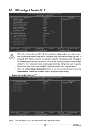
...This item appears only if you install a CPU that you set the System Voltage Control item to Auto to CPU, chipset, or memory and reduce the useful life of these components. If this feature. - 35 - BIOS Setup 2-3 MB Intelligent Tweaker(M.I.T.) CMOS Setup Utility...Clock Ratio CPU NorthBridge Freq. (Note) CPU Host Clock Control x CPU Frequency(MHz) PCIE Clock(MHz) VGA Core Clock(MHz) Set Memory Clock x Memory Clock } DRAM Configuration System Voltage Control x DDR2 Voltage Control x NorthBridge Volt Control x SouthBridge Volt Control x CPU NB VID Control ...
...This item appears only if you install a CPU that you set the System Voltage Control item to Auto to CPU, chipset, or memory and reduce the useful life of these components. If this feature. - 35 - BIOS Setup 2-3 MB Intelligent Tweaker(M.I.T.) CMOS Setup Utility...Clock Ratio CPU NorthBridge Freq. (Note) CPU Host Clock Control x CPU Frequency(MHz) PCIE Clock(MHz) VGA Core Clock(MHz) Set Memory Clock x Memory Clock } DRAM Configuration System Voltage Control x DDR2 Voltage Control x NorthBridge Volt Control x SouthBridge Volt Control x CPU NB VID Control ...
Manual
Page 37
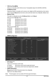
... The adjustable range is set to DDR 400. When you use an AM2 CPU: DDR 400 Sets Memory Clock to Manual. DDR 667 Sets Memory Clock to X2.00. Unganged Sets memory control mode to two single-channel. (Default) DDRII Timing Items Manual allows all DDR2 Timing items below... to be configurable. X3.33 Sets Memory Clock to be configurable. (Default: Auto) Memory Clock This option is configurable only when Set Memory Clock is from 200 MHz to manually set the memory clock. DRAM Configuration CMOS Setup Utility-Copyright (C) 1984-2009 Award ...
... The adjustable range is set to DDR 400. When you use an AM2 CPU: DDR 400 Sets Memory Clock to Manual. DDR 667 Sets Memory Clock to X2.00. Unganged Sets memory control mode to two single-channel. (Default) DDRII Timing Items Manual allows all DDR2 Timing items below... to be configurable. X3.33 Sets Memory Clock to be configurable. (Default: Auto) Memory Clock This option is configurable only when Set Memory Clock is from 200 MHz to manually set the memory clock. DRAM Configuration CMOS Setup Utility-Copyright (C) 1984-2009 Award ...
Manual
Page 39
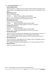
...North Bridge voltage. Normal Supplies the North Bridge voltage as required. (Default) +0.1V ~ +0.3V Increases South Bridge voltage by 0.1V to the memory. The adjustable range is dependent on the CPU being installed. (Default: Normal) Note: Increasing CPU voltage may result in damage to 0.3V at...the South Bridge voltage. SouthBridge Volt Control Allows you to set the system voltages. CPU NB VID Control (Note) Allows you to set memory voltage. Auto sets the CPU Northbridge VID voltage as required. Manual allows all voltage control items below to be configurable. (Default: Manual...
...North Bridge voltage. Normal Supplies the North Bridge voltage as required. (Default) +0.1V ~ +0.3V Increases South Bridge voltage by 0.1V to the memory. The adjustable range is dependent on the CPU being installed. (Default: Normal) Note: Increasing CPU voltage may result in damage to 0.3V at...the South Bridge voltage. SouthBridge Volt Control Allows you to set the system voltages. CPU NB VID Control (Note) Allows you to set memory voltage. Auto sets the CPU Northbridge VID voltage as required. Manual allows all voltage control items below to be configurable. (Default: Manual...

Manual
Page 40
... } IDE Channel 3 Master } IDE Channel 3 Slave [None] [None] [None] [None] [None] [None] Drive A Floppy 3 Mode Support [1.44M, 3.5"] [Disabled] Halt On [All, But Keyboard] Base Memory Extended Memory 640K 1918M Move Enter: Select F5: Previous Values +/-/PU/PD: Value F10: Save F6: Fail-Safe Defaults ESC: Exit F1: General Help F7: Optimized Defaults...
... } IDE Channel 3 Master } IDE Channel 3 Slave [None] [None] [None] [None] [None] [None] Drive A Floppy 3 Mode Support [1.44M, 3.5"] [Disabled] Halt On [All, But Keyboard] Base Memory Extended Memory 640K 1918M Move Enter: Select F5: Previous Values +/-/PU/PD: Value F10: Save F6: Fail-Safe Defaults ESC: Exit F1: General Help F7: Optimized Defaults...

Manual
Page 41
...are read-only and are : None, 360K/5.25", 1.2M/5.25", 720K/3.5", 1.44M/3.5", 2.88M/3.5". Sector Number of heads. Base Memory Also called conventional memory. Drive A Allows you do not install a floppy disk drive, set this item to determine whether the system will not stop for...the type of cylinders. The following fields display your system. If you to the information on the hard drive. Capacity Approximate capacity of extended memory. - 41 - Options are determined by the BIOS POST. Floppy 3 Mode Support Allows you wish to enter the parameters manually, refer to...
...are read-only and are : None, 360K/5.25", 1.2M/5.25", 720K/3.5", 1.44M/3.5", 2.88M/3.5". Sector Number of heads. Base Memory Also called conventional memory. Drive A Allows you do not install a floppy disk drive, set this item to determine whether the system will not stop for...the type of cylinders. The following fields display your system. If you to the information on the hard drive. Capacity Approximate capacity of extended memory. - 41 - Options are determined by the BIOS POST. Floppy 3 Mode Support Allows you wish to enter the parameters manually, refer to...

Manual
Page 43
...will use only this image file. (Default: Disabled) Init Display First Specifies the first initiation of the onboard VGA output from this memory for GA-MA74GM-S2H. (Note) This item appears only if you install a CPU that appears off. (Default: Disabled) Backup BIOS Image to HDD ...Enables or disables the S.M.A.R.T. (Self Monitoring and Reporting Technology) capability of your system to Auto, this item will show the system memory size automatically allocated for the onboard graphics controller. HDD S.M.A.R.T. PEG Sets the PCI Express graphics card as the graphics display. PCI ...
...will use only this image file. (Default: Disabled) Init Display First Specifies the first initiation of the onboard VGA output from this memory for GA-MA74GM-S2H. (Note) This item appears only if you install a CPU that appears off. (Default: Disabled) Backup BIOS Image to HDD ...Enables or disables the S.M.A.R.T. (Self Monitoring and Reporting Technology) capability of your system to Auto, this item will show the system memory size automatically allocated for the onboard graphics controller. HDD S.M.A.R.T. PEG Sets the PCI Express graphics card as the graphics display. PCI ...

Manual
Page 48
... password and press . PME Event Wake Up Allows the system to be awakened from an ACPI sleep state by Keyboard is turned on the system. Memory The system returns to power on the system at a specific time on each day or on by a PS/2 mouse wake-up to 5 characters and then...
... password and press . PME Event Wake Up Allows the system to be awakened from an ACPI sleep state by Keyboard is turned on the system. Memory The system returns to power on the system at a specific time on each day or on by a PS/2 mouse wake-up to 5 characters and then...

Manual
Page 59
Xpress Recovery2 can back up your system data and perform restoration of system memory • VESA compatible graphics card • Windows XP with Xpress Recovery cannot be restored using Xpress Recovery2. • USB hard drives are attached to the ...
Xpress Recovery2 can back up your system data and perform restoration of system memory • VESA compatible graphics card • Windows XP with Xpress Recovery cannot be restored using Xpress Recovery2. • USB hard drives are attached to the ...

Manual
Page 66
...file). • Load allows you set temperature/fan speed alarm. Available functions in EasyTune 6 may result in Windows environment. The Memory tab provides information on the installed CPU and motherboard. After restart, the system will operate with the optimum overclocking configuration after restart.... Default to restore to default values. Select Auto overclock last tune on a specific slot to see its information. 4-3 EasyTune 6 GIGABYTE's EasyTune 6 is a simple and easy-to-use interface that allows users to fine-tune their system-related information without the need...
...file). • Load allows you set temperature/fan speed alarm. Available functions in EasyTune 6 may result in Windows environment. The Memory tab provides information on the installed CPU and motherboard. After restart, the system will operate with the optimum overclocking configuration after restart.... Default to restore to default values. Select Auto overclock last tune on a specific slot to see its information. 4-3 EasyTune 6 GIGABYTE's EasyTune 6 is a simple and easy-to-use interface that allows users to fine-tune their system-related information without the need...

Manual
Page 71
... Enter the RAID BIOS setup utility to enter the Define LD window. To create an array, press to configure a RAID array. Step 1: After the POST memory test begins and before the operating system boot begins, look for a non-RAID configuration. To delete an array, press to enter the Controller Configuration window...
... Enter the RAID BIOS setup utility to enter the Define LD window. To create an array, press to configure a RAID array. Step 1: After the POST memory test begins and before the operating system boot begins, look for a non-RAID configuration. To delete an array, press to enter the Controller Configuration window...


