Manual
Page 1
GA-M85M-US2H AM2+/AM2 socket motherboard for AMD PhenomTM II X3 processor/AMD PhenomTM II X4 processor/ AMD PhenomTM FX processor/AMD PhenomTM X4 processor/ AMD PhenomTM X3 processor/AMD AthlonTM X2 processor/ AMD AthlonTM processor/AMD SempronTM X2 processor/ AMD SempronTM processor User's Manual Rev. 1001 12ME-M85MU2H-1001R
GA-M85M-US2H AM2+/AM2 socket motherboard for AMD PhenomTM II X3 processor/AMD PhenomTM II X4 processor/ AMD PhenomTM FX processor/AMD PhenomTM X4 processor/ AMD PhenomTM X3 processor/AMD AthlonTM X2 processor/ AMD AthlonTM processor/AMD SempronTM X2 processor/ AMD SempronTM processor User's Manual Rev. 1001 12ME-M85MU2H-1001R
Manual
Page 2
Motherboard GA-M85M-US2H Feb. 24, 2009 Motherboard GA-M85M-US2H Feb. 24, 2009
Motherboard GA-M85M-US2H Feb. 24, 2009 Motherboard GA-M85M-US2H Feb. 24, 2009
Manual
Page 3
..., drivers, or when looking for technical information. All rights reserved. For product-related information, check on our website at: http://www.gigabyte.com.tw Identifying Your Motherboard Revision The revision number on our website. Copyright © 2009 GIGA-BYTE TECHNOLOGY CO., LTD. Example: - 3 - Disclaimer Information in any form or by copyright laws...
..., drivers, or when looking for technical information. All rights reserved. For product-related information, check on our website at: http://www.gigabyte.com.tw Identifying Your Motherboard Revision The revision number on our website. Copyright © 2009 GIGA-BYTE TECHNOLOGY CO., LTD. Example: - 3 - Disclaimer Information in any form or by copyright laws...

Manual
Page 4
Table of Contents Box Contents ...6 OptionalItems ...6 GA-M85M-US2H Motherboard Layout 7 Block Diagram ...8 Chapter 1 Hardware Installation 9 1-1 Installation Precautions 9 1-2 Product Specifications 10 1-3 Installing the CPU and CPU Cooler 13 1-3-1 Installing the CPU 13 1-3-2 Installing the CPU ...
Table of Contents Box Contents ...6 OptionalItems ...6 GA-M85M-US2H Motherboard Layout 7 Block Diagram ...8 Chapter 1 Hardware Installation 9 1-1 Installation Precautions 9 1-2 Product Specifications 10 1-3 Installing the CPU and CPU Cooler 13 1-3-1 Installing the CPU 13 1-3-2 Installing the CPU ...
Manual
Page 6
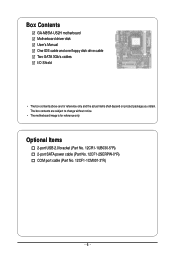
The box contents are for reference only. Optional Items 2-port USB 2.0 bracket (Part No. 12CR1-1UB030-5*R) 2-port SATA power cable (Part No. 12CF1-2SERPW-0*R) COM port cable (Part No. 12CF1-1CM001-3*R) - 6 - Box Contents GA-M85M-US2H motherboard Motherboard driver disk User's Manual One IDE cable and one floppy disk drive cable Two SATA 3Gb/s cables I/O Shield • The box contents above are subject to change without notice. • The motherboard image is for reference only and the actual items shall depend on product package you obtain.
The box contents are for reference only. Optional Items 2-port USB 2.0 bracket (Part No. 12CR1-1UB030-5*R) 2-port SATA power cable (Part No. 12CF1-2SERPW-0*R) COM port cable (Part No. 12CF1-1CM001-3*R) - 6 - Box Contents GA-M85M-US2H motherboard Motherboard driver disk User's Manual One IDE cable and one floppy disk drive cable Two SATA 3Gb/s cables I/O Shield • The box contents above are subject to change without notice. • The motherboard image is for reference only and the actual items shall depend on product package you obtain.
Manual
Page 7
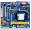
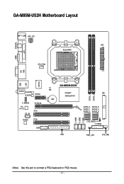
GA-M85M-US2H Motherboard Layout KB(Note)_USB ATX_12V ATX Socket AM2 CPU_FAN COAXIAL LPT HDMI VGA DVI IT8718 LAN USB AUDIO M_BIOS B_BIOS PCIEX1 F_AUDIO RTL 8211CL CD_IN PCIEX16 PCI1 CODEC PCI2 COM CI BAT GA-M85M-US2H NVIDIA® GeForce 8100 DDR2_1 DDR2_2 IDE SATA2_2 SATA2_5 SATA2_1 SATA2_4 SATA2_0 SATA2_3 F_USB3 F_USB2 F_USB1 CLR_CMOS F_PANEL FDD PWR_LED SYS_FAN (Note) Use this port to connect a PS/2 keyboard or PS/2 mouse. - 7 -
GA-M85M-US2H Motherboard Layout KB(Note)_USB ATX_12V ATX Socket AM2 CPU_FAN COAXIAL LPT HDMI VGA DVI IT8718 LAN USB AUDIO M_BIOS B_BIOS PCIEX1 F_AUDIO RTL 8211CL CD_IN PCIEX16 PCI1 CODEC PCI2 COM CI BAT GA-M85M-US2H NVIDIA® GeForce 8100 DDR2_1 DDR2_2 IDE SATA2_2 SATA2_5 SATA2_1 SATA2_4 SATA2_0 SATA2_3 F_USB3 F_USB2 F_USB1 CLR_CMOS F_PANEL FDD PWR_LED SYS_FAN (Note) Use this port to connect a PS/2 keyboard or PS/2 mouse. - 7 -
Manual
Page 9
... Installation These stickers are required for warranty validation. • Always remove the AC power by unplugging the power cord from the motherboard, make sure the power supply has been turned off. • Before turning on the power, make sure they are connected tightly... such as a result of the product, please consult a certified computer technician. - 9 - Chapter 1 Hardware Installation 1-1 Installation Precautions The motherboard contains numerous delicate electronic circuits and components which can lead to damage to system components as well as physical harm to the user. •...
... Installation These stickers are required for warranty validation. • Always remove the AC power by unplugging the power cord from the motherboard, make sure the power supply has been turned off. • Before turning on the power, make sure they are connected tightly... such as a result of the product, please consult a certified computer technician. - 9 - Chapter 1 Hardware Installation 1-1 Installation Precautions The motherboard contains numerous delicate electronic circuits and components which can lead to damage to system components as well as physical harm to the user. •...

Manual
Page 10
...processor/ AMD PhenomTM X3 processor/AMD AthlonTM X2 processor/ AMD AthlonTM processor/AMD SempronTM X2 processor/ AMD SempronTM processor (Go to GIGABYTE's website for the latest CPU support list.) 5200/2000 MT/s NVIDIA® GeForce 8100 chipset 2 x 1.8V DDR2 DIMM ...GIGABYTE's website for the latest memory support list.) Realtek ALC888 codec High Definition Audio 2/4/5.1/7.1-channel (Note 2) Support for S/PDIF Out Support for SATA RAID 0, RAID 1, RAID 0+1, RAID 5, and JBOD iTE IT8718 chip: - 1 x floppy disk drive connector supporting up to the internal USB headers) GA-M85M-US2H Motherboard...
...processor/ AMD PhenomTM X3 processor/AMD AthlonTM X2 processor/ AMD AthlonTM processor/AMD SempronTM X2 processor/ AMD SempronTM processor (Go to GIGABYTE's website for the latest CPU support list.) 5200/2000 MT/s NVIDIA® GeForce 8100 chipset 2 x 1.8V DDR2 DIMM ...GIGABYTE's website for the latest memory support list.) Realtek ALC888 codec High Definition Audio 2/4/5.1/7.1-channel (Note 2) Support for S/PDIF Out Support for SATA RAID 0, RAID 1, RAID 0+1, RAID 5, and JBOD iTE IT8718 chip: - 1 x floppy disk drive connector supporting up to the internal USB headers) GA-M85M-US2H Motherboard...

Manual
Page 12
GA-M85M-US2H Motherboard - 12 - Unique Features Bundled Software Operating System Form Factor Support for @BIOS Support for Q-Flash Support for Virtual Dual BIOS Support ... 7) Whether the CPU fan speed control function is supported will depend on the CPU cooler you install. (Note 8) Available functions in EasyTune may differ by motherboard model. (Note 9) Due to the hardware limitation, you must install the AMD AM3 PhenomTM II/AM2+ PhenomTM Series CPU toenable support for Easy Energy Saver...
GA-M85M-US2H Motherboard - 12 - Unique Features Bundled Software Operating System Form Factor Support for @BIOS Support for Q-Flash Support for Virtual Dual BIOS Support ... 7) Whether the CPU fan speed control function is supported will depend on the CPU cooler you install. (Note 8) Available functions in EasyTune may differ by motherboard model. (Note 9) Due to the hardware limitation, you must install the AMD AM3 PhenomTM II/AM2+ PhenomTM Series CPU toenable support for Easy Energy Saver...
Manual
Page 13
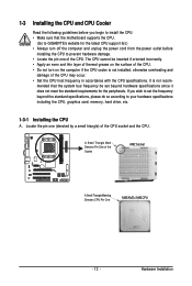
If you begin to install the CPU: • Make sure that the motherboard supports the CPU. (Go to GIGABYTE's website for the peripherals. The CPU cannot be set the frequency beyond hardware specifications since it does not meet the standard requirements for the latest ...
If you begin to install the CPU: • Make sure that the motherboard supports the CPU. (Go to GIGABYTE's website for the peripherals. The CPU cannot be set the frequency beyond hardware specifications since it does not meet the standard requirements for the latest ...
Manual
Page 14
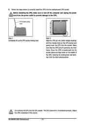
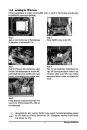
... the CPU pin one finger down on the CPU socket and gently insert the CPU into the socket. Adjust the CPU orientation if this occurs. GA-M85M-US2H Motherboard - 14 - Before installing the CPU, make sure to turn off the computer and unplug the power cord from the power outlet to prevent damage to...
... the CPU pin one finger down on the CPU socket and gently insert the CPU into the socket. Adjust the CPU orientation if this occurs. GA-M85M-US2H Motherboard - 14 - Before installing the CPU, make sure to turn off the computer and unplug the power cord from the power outlet to prevent damage to...
Manual
Page 15
... CPU. 1-3-2 Installing the CPU Cooler Follow the steps below to correctly install the CPU cooler on the CPU. (The following procedure uses the GIGABYTE cooler as the picture above shows) to lock into place. (Refer to your CPU cooler installation manual for instructions on installing the cooler.) Step... 5: Finally, attach the power connector of the CPU cooler to the CPU fan header (CPU_FAN) on the motherboard. Use extreme care when removing the CPU cooler because the thermal grease/tape between the CPU cooler and CPU may damage the CPU. - 15 ...
... CPU. 1-3-2 Installing the CPU Cooler Follow the steps below to correctly install the CPU cooler on the CPU. (The following procedure uses the GIGABYTE cooler as the picture above shows) to lock into place. (Refer to your CPU cooler installation manual for instructions on installing the cooler.) Step... 5: Finally, attach the power connector of the CPU cooler to the CPU fan header (CPU_FAN) on the motherboard. Use extreme care when removing the CPU cooler because the thermal grease/tape between the CPU cooler and CPU may damage the CPU. - 15 ...

Manual
Page 16
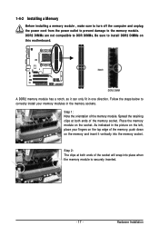
GA-M85M-US2H Motherboard - 16 - When enabling Dual Channel mode with two memory modules, it is recommended that memory of the same capacity, brand, speed, and chips be used . (Go to GIGABYTE's website for the latest memory support list.) • Always turn off the computer and unplug the power cord from the power outlet before installing...
GA-M85M-US2H Motherboard - 16 - When enabling Dual Channel mode with two memory modules, it is recommended that memory of the same capacity, brand, speed, and chips be used . (Go to GIGABYTE's website for the latest memory support list.) • Always turn off the computer and unplug the power cord from the power outlet before installing...
Manual
Page 17
... to DDR DIMMs. Be sure to the memory module. Step 2: The clips at both ends of the memory module. Place the memory module on this motherboard. Spread the retaining clips at both ends of the memory, push down on the left, place your memory modules in one direction. 1-4-2 Installing a Memory Before...
... to DDR DIMMs. Be sure to the memory module. Step 2: The clips at both ends of the memory module. Place the memory module on this motherboard. Spread the retaining clips at both ends of the memory, push down on the left, place your memory modules in one direction. 1-4-2 Installing a Memory Before...

Manual
Page 18
...• Installing a Graphics Card: Gently push down on the slot and then lift the card straight out from the chassis back panel. 2. GA-M85M-US2H Motherboard - 18 - PCI Express x1 Slot PCI Express x16 Slot PCI Slot Follow the steps below to correctly install your expansion card(s). 7. If ...computer and unplug the power cord from the power outlet before you begin to install an expansion card: • Make sure the motherboard supports the expansion card. 1-5 Installing an Expansion Card Read the following guidelines before installing an expansion card to prevent hardware damage. ...
...• Installing a Graphics Card: Gently push down on the slot and then lift the card straight out from the chassis back panel. 2. GA-M85M-US2H Motherboard - 18 - PCI Express x1 Slot PCI Express x16 Slot PCI Slot Follow the steps below to correctly install your expansion card(s). 7. If ...computer and unplug the power cord from the power outlet before you begin to install an expansion card: • Make sure the motherboard supports the expansion card. 1-5 Installing an Expansion Card Read the following guidelines before installing an expansion card to prevent hardware damage. ...
Manual
Page 19
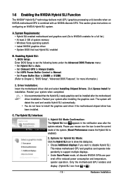
... 2, "BIOS Setup", "Advanced BIOS Features", for reduced power consumption and temperature, quieter operation. Hardware Installation Driver Installation: Insert the motherboard driver disk and select Installing Chipset Drivers. Click Xpress Install for a full list.) • At least 2 GB of the system... The NVIDIA® Hybrid SLI® technology delivers multi-GPU (graphics processing unit) benefits when an NVIDIA motherboard GPU is enabled.) 2. This makes motherboard GPU and graphics card operate independently to disable Hybrid SLI. C. A. Options for Hybrid SLI Mode: Click the...
... 2, "BIOS Setup", "Advanced BIOS Features", for reduced power consumption and temperature, quieter operation. Hardware Installation Driver Installation: Insert the motherboard driver disk and select Installing Chipset Drivers. Click Xpress Install for a full list.) • At least 2 GB of the system... The NVIDIA® Hybrid SLI® technology delivers multi-GPU (graphics processing unit) benefits when an NVIDIA motherboard GPU is enabled.) 2. This makes motherboard GPU and graphics card operate independently to disable Hybrid SLI. C. A. Options for Hybrid SLI Mode: Click the...
Manual
Page 20
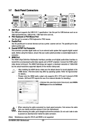
...monitor being used. • After installing the HDMI device, make sure the default device for USB devices such as a printer, scanner and etc. GA-M85M-US2H Motherboard - 20 - PS/2 Keyboard or PS/2 Mouse Port Use this port to this port. Before using this port for sound playback is not supported..... Coaxial S/PDIF Out Connector This connector provides digital audio out to an external audio system that your device and then remove it from the motherboard. • When removing the cable, pull it side to side to a back panel connector, first remove the cable from your audio system...
...monitor being used. • After installing the HDMI device, make sure the default device for USB devices such as a printer, scanner and etc. GA-M85M-US2H Motherboard - 20 - PS/2 Keyboard or PS/2 Mouse Port Use this port to this port. Before using this port for sound playback is not supported..... Coaxial S/PDIF Out Connector This connector provides digital audio out to an external audio system that your device and then remove it from the motherboard. • When removing the cable, pull it side to side to a back panel connector, first remove the cable from your audio system...

Manual
Page 21
... is occurring - 21 - Connect a monitor that supports DVI-D connection to this port. Connect a monitor that supports D-Sub connection to this port. Dual Display Configurations: This motherboard provides three ports for more information) • Playback software: CyberLink PowerDVD 8.0 or above processor • Memory: Two 1 GB DDR2 800 memory modules with dual channel...
... is occurring - 21 - Connect a monitor that supports DVI-D connection to this port. Connect a monitor that supports D-Sub connection to this port. Dual Display Configurations: This motherboard provides three ports for more information) • Playback software: CyberLink PowerDVD 8.0 or above processor • Memory: Two 1 GB DDR2 800 memory modules with dual channel...
Manual
Page 22
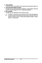
... audio, you need connect with the port of HD Audio standard via front panel and enable the multi-channel audio feature through the audio driver. GA-M85M-US2H Motherboard - 22 - Refer to the instructions on setting up a 2/4/5.1/7.1-channel audio configuration in jack. Line Out Jack (Front Speaker Out, Green) The default line out jack...
... audio, you need connect with the port of HD Audio standard via front panel and enable the multi-channel audio feature through the audio driver. GA-M85M-US2H Motherboard - 22 - Refer to the instructions on setting up a 2/4/5.1/7.1-channel audio configuration in jack. Line Out Jack (Front Speaker Out, Green) The default line out jack...
Manual
Page 23
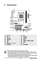
... 9) BAT 10) F_PANEL 11) F_AUDIO 12) CD_IN 13) F_USB1 / F_USB2 / F_USB3 14) COM 15) CI 16) CLR_CMOS Read the following guidelines before turning on the motherboard. - 23 - Hardware Installation
... 9) BAT 10) F_PANEL 11) F_AUDIO 12) CD_IN 13) F_USB1 / F_USB2 / F_USB3 14) COM 15) CI 16) CLR_CMOS Read the following guidelines before turning on the motherboard. - 23 - Hardware Installation


