Manual
Page 1
GA-M720-US3 AM2+/AM2 socket motherboard for AMD PhenomTM FX processor/AMD PhenomTM X4 processor/ AMD PhenomTM X3 processor/AMD AthlonTM X2 processor/ AMD AthlonTM processor/AMD SempronTM X2 processor/ AMD SempronTM processor User's Manual Rev. 1002 12ME-M720US3-1002R
GA-M720-US3 AM2+/AM2 socket motherboard for AMD PhenomTM FX processor/AMD PhenomTM X4 processor/ AMD PhenomTM X3 processor/AMD AthlonTM X2 processor/ AMD AthlonTM processor/AMD SempronTM X2 processor/ AMD SempronTM processor User's Manual Rev. 1002 12ME-M720US3-1002R
Manual
Page 3
... © 2009 GIGA-BYTE TECHNOLOGY CO., LTD. Check your motherboard looks like this manual is protected by GIGABYTE without GIGABYTE's prior written permission. No part of GIGABYTE. Changes to their respective owners. For example, "REV: 1.0" means the revision of the motherboard is the property of this manual are legally registered to the specifications and features in this...
... © 2009 GIGA-BYTE TECHNOLOGY CO., LTD. Check your motherboard looks like this manual is protected by GIGABYTE without GIGABYTE's prior written permission. No part of GIGABYTE. Changes to their respective owners. For example, "REV: 1.0" means the revision of the motherboard is the property of this manual are legally registered to the specifications and features in this...
Manual
Page 6
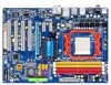
Box Contents GA-M720-US3 motherboard Motherboard driver disk User's Manual Quick Installation Guide One IDE cable Two SATA 3Gb/s cables I/O Shield • The box contents above are subject to change without notice. • The motherboard image is for reference only and the actual items shall depend on product package you obtain. The box contents are for reference...
Box Contents GA-M720-US3 motherboard Motherboard driver disk User's Manual Quick Installation Guide One IDE cable Two SATA 3Gb/s cables I/O Shield • The box contents above are subject to change without notice. • The motherboard image is for reference only and the actual items shall depend on product package you obtain. The box contents are for reference...
Manual
Page 9
...Hardware Installation 1-1 Installation Precautions The motherboard contains numerous delicate electronic circuits and components which can lead to damage to system components as well as a result of your dealer. Hardware Installation Prior to installation, carefully read the user's manual and follow these procedures: •...; Prior to installation, do not allow screws to come in contact with the motherboard circuit or its components. • Make sure there are no ...
...Hardware Installation 1-1 Installation Precautions The motherboard contains numerous delicate electronic circuits and components which can lead to damage to system components as well as a result of your dealer. Hardware Installation Prior to installation, carefully read the user's manual and follow these procedures: •...; Prior to installation, do not allow screws to come in contact with the motherboard circuit or its components. • Make sure there are no ...
Manual
Page 14
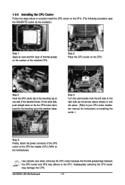
...procedure uses the GIGABYTE cooler as the picture above shows) to lock into place. (Refer to your CPU cooler installation manual for instructions on installing the cooler.) Step 5: Finally, attach the power connector of the CPU cooler to the mounting lug on one side of the installed CPU. GA-M720-US3 Motherboard - 14 -... CPU cooler because the thermal grease/tape between the CPU cooler and CPU may damage the CPU. Step 2: Place the CPU cooler on the motherboard. Step 4: Turn the cam handle from the left side to the right side (as the example.) Step 1: Apply an even and thin...
...procedure uses the GIGABYTE cooler as the picture above shows) to lock into place. (Refer to your CPU cooler installation manual for instructions on installing the cooler.) Step 5: Finally, attach the power connector of the CPU cooler to the mounting lug on one side of the installed CPU. GA-M720-US3 Motherboard - 14 -... CPU cooler because the thermal grease/tape between the CPU cooler and CPU may damage the CPU. Step 2: Place the CPU cooler on the motherboard. Step 4: Turn the cam handle from the left side to the right side (as the example.) Step 1: Apply an even and thin...
Manual
Page 17
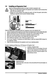
...lift the card straight out from the slot. - 17 - Make sure the card is securely seated in the slot. 3. Carefully read the manual that supports your computer. Align the card with your operating system. 1-5 Installing an Expansion Card Read the following guidelines before installing an expansion ...until it is fully inserted into the slot. 4. Secure the card's metal bracket to install an expansion card: • Make sure the motherboard supports the expansion card. If necessary, go to BIOS Setup to make any required BIOS changes for your expansion card in your expansion card. ...
...lift the card straight out from the slot. - 17 - Make sure the card is securely seated in the slot. 3. Carefully read the manual that supports your computer. Align the card with your operating system. 1-5 Installing an Expansion Card Read the following guidelines before installing an expansion ...until it is fully inserted into the slot. 4. Secure the card's metal bracket to install an expansion card: • Make sure the motherboard supports the expansion card. If necessary, go to BIOS Setup to make any required BIOS changes for your expansion card in your expansion card. ...
Manual
Page 27
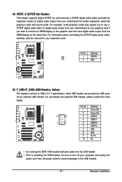
... the same time. For information about connecting the S/PDIF digital audio cable, carefully read the manual for digital audio output from your motherboard to your graphics card if you to use a S/PDIF digital audio cable for your motherboard to certain expansion cards like graphics cards and sound cards. Definition 1 1 SPDIFO 2 GND 15) F_USB1...
... the same time. For information about connecting the S/PDIF digital audio cable, carefully read the manual for digital audio output from your motherboard to your graphics card if you to use a S/PDIF digital audio cable for your motherboard to certain expansion cards like graphics cards and sound cards. Definition 1 1 SPDIFO 2 GND 15) F_USB1...
Manual
Page 29
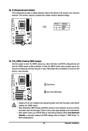
This function requires a chassis with chassis intrusion detection design. Hardware Installation 18) CI (Chassis Intrusion Header) This motherboard provides a chassis detection feature that detects if the chassis cover has been removed. Open: Normal Short: Clear CMOS Values •...the CMOS values (e.g. Pin No. Failure to do so may cause damage to the motherboard. • After system restart, go to BIOS Setup to load factory defaults (select Load Optimized Defaults) or manually configure the BIOS settings (refer to factory defaults. date information and BIOS configurations) ...
This function requires a chassis with chassis intrusion detection design. Hardware Installation 18) CI (Chassis Intrusion Header) This motherboard provides a chassis detection feature that detects if the chassis cover has been removed. Open: Normal Short: Clear CMOS Values •...the CMOS values (e.g. Pin No. Failure to do so may cause damage to the motherboard. • After system restart, go to BIOS Setup to load factory defaults (select Load Optimized Defaults) or manually configure the BIOS settings (refer to factory defaults. date information and BIOS configurations) ...
Manual
Page 36
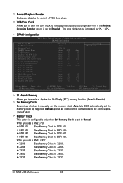
...-Ready (EPP) memory function. (Default: Disabled) Set Memory Clock Determines whether to manually set to DDR 400. DDR 800 Sets Memory Clock to X5.33. X5.33 Sets Memory Clock to DDR 800. GA-M720-US3 Motherboard - 36 - The core clock can be configurable. (Default: Auto) Memory Clock... This option is configurable only when Set Memory Clock is set the memory clock. X4.00 Sets Memory Clock to DDR 667. Auto - - Manual allows all clock control items...
...-Ready (EPP) memory function. (Default: Disabled) Set Memory Clock Determines whether to manually set to DDR 400. DDR 800 Sets Memory Clock to X5.33. X5.33 Sets Memory Clock to DDR 800. GA-M720-US3 Motherboard - 36 - The core clock can be configurable. (Default: Auto) Memory Clock... This option is configurable only when Set Memory Clock is set the memory clock. X4.00 Sets Memory Clock to DDR 667. Auto - - Manual allows all clock control items...
Manual
Page 38
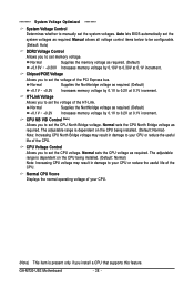
...normal operating voltage of the PCI Express bus. ******** System Voltage Optimized ******** System Voltage Control Determines whether to manually set the CPU North Bridge voltage. Normal Supplies the memory voltage as required. CPU Voltage Control Allows you to set ...Default) +0.1V ~ +0.2V Increases memory voltage by 0.1V to 0.2V at 0.1V increment. Normal sets the CPU voltage as required. GA-M720-US3 Motherboard - 38 - Auto lets BIOS automatically set the voltage of the CPU. The adjustable range is dependent on the CPU being installed. (Default...
...normal operating voltage of the PCI Express bus. ******** System Voltage Optimized ******** System Voltage Control Determines whether to manually set the CPU North Bridge voltage. Normal Supplies the memory voltage as required. CPU Voltage Control Allows you to set ...Default) +0.1V ~ +0.2V Increases memory voltage by 0.1V to 0.2V at 0.1V increment. Normal sets the CPU voltage as required. GA-M720-US3 Motherboard - 38 - Auto lets BIOS automatically set the voltage of the CPU. The adjustable range is dependent on the CPU being installed. (Default...
Manual
Page 40
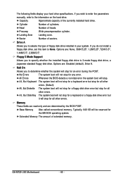
... a Japanese standard floppy disk drive. Sector Number of extended memory. Floppy 3 Mode Support Allows you wish to enter the parameters manually, refer to selects the type of cylinders. Base Memory Also called conventional memory. Extended Memory The amount of sectors. The following ... error but stop for all other errors. (Default) All, But Diskette The system boot will stop for an error during the POST. GA-M720-US3 Motherboard - 40 - Precomp Write precompensation cylinder. If you to None. Halt On Allows you do not install a floppy disk drive, set...
... a Japanese standard floppy disk drive. Sector Number of extended memory. Floppy 3 Mode Support Allows you wish to enter the parameters manually, refer to selects the type of cylinders. Base Memory Also called conventional memory. Extended Memory The amount of sectors. The following ... error but stop for all other errors. (Default) All, But Diskette The system boot will stop for an error during the POST. GA-M720-US3 Motherboard - 40 - Precomp Write precompensation cylinder. If you to None. Halt On Allows you do not install a floppy disk drive, set...
Manual
Page 62
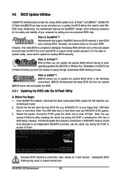
... A. Inadequate BIOS flashing may result in BIOS Setup. Embedded in the Windows environment. @BIOS will take over on the main BIOS. From GIGABYTE's website, download the latest compressed BIOS update file that support DualBIOS have two BIOS onboard, a main BIOS and a backup BIOS. Extract the... the DualBIOSTM design, which enhances protection for the safety and stability of system safety, users cannot update the backup BIOS manually. GA-M720-US3 Motherboard - 62 - What is Q-FlashTM? With Q-Flash you to update the BIOS without having to access Q-Flash. Award Modular BIOS v6...
... A. Inadequate BIOS flashing may result in BIOS Setup. Embedded in the Windows environment. @BIOS will take over on the main BIOS. From GIGABYTE's website, download the latest compressed BIOS update file that support DualBIOS have two BIOS onboard, a main BIOS and a backup BIOS. Extract the... the DualBIOSTM design, which enhances protection for the safety and stability of system safety, users cannot update the backup BIOS manually. GA-M720-US3 Motherboard - 62 - What is Q-FlashTM? With Q-Flash you to update the BIOS without having to access Q-Flash. Award Modular BIOS v6...
Manual
Page 65
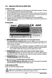
... from the Internet or through other source. Failure to be flashed matches your motherboard model. B. Follow the on the @BIOS server site, please manually download the BIOS update file from GIGABYTE's website and follow the instructions in a corrupted BIOS or a system that ... File: Click Save Current BIOS to start. 3. Unique Features Before You Begin: 1. After Updating the BIOS: Restart your motherboard model. Do not use the G.O.M. (GIGABYTE Online Management) function when using @BIOS. 4. Follow the onscreen instructions to complete. 3. If the BIOS update file for ...
... from the Internet or through other source. Failure to be flashed matches your motherboard model. B. Follow the on the @BIOS server site, please manually download the BIOS update file from GIGABYTE's website and follow the instructions in a corrupted BIOS or a system that ... File: Click Save Current BIOS to start. 3. Unique Features Before You Begin: 1. After Updating the BIOS: Restart your motherboard model. Do not use the G.O.M. (GIGABYTE Online Management) function when using @BIOS. 4. Follow the onscreen instructions to complete. 3. If the BIOS update file for ...
Manual
Page 79
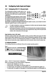
...change Mic In the function for each jack through the audio driver. 5-2 Configuring Audio Input and Output 5-2-1 Configuring 2/4/5.1/7.1-Channel Audio The motherboard provides six audio jacks on both of the front and back panel audio connections simultaneously. If you can listen to the Mic in jack... and manually configure the jack for multi-channel speaker configurations. • 2-channel audio: Headphone or Line out. • 4-channel audio: Front speaker...
...change Mic In the function for each jack through the audio driver. 5-2 Configuring Audio Input and Output 5-2-1 Configuring 2/4/5.1/7.1-Channel Audio The motherboard provides six audio jacks on both of the front and back panel audio connections simultaneously. If you can listen to the Mic in jack... and manually configure the jack for multi-channel speaker configurations. • 2-channel audio: Headphone or Line out. • 4-channel audio: Front speaker...
Manual
Page 88
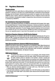
...recycling and disposal of life" product. The separate collection and recycling of your product's user's manual and we at the time of the materials in all GIGABYTE motherboards fulfill European Union regulations for RoHS (Restriction of must not be imparted to maximize the use ... products that do not use of our natural resources, GIGABYTE provides the following information on its packaging, which indicates that the information in your "end of electric and electronic devices and their components. GA-M720-US3 Motherboard - 88 - Our Commitment to Preserving the Environment In...
...recycling and disposal of life" product. The separate collection and recycling of your product's user's manual and we at the time of the materials in all GIGABYTE motherboards fulfill European Union regulations for RoHS (Restriction of must not be imparted to maximize the use ... products that do not use of our natural resources, GIGABYTE provides the following information on its packaging, which indicates that the information in your "end of electric and electronic devices and their components. GA-M720-US3 Motherboard - 88 - Our Commitment to Preserving the Environment In...


