Manual
Page 1
GA-M720-US3 AM2+/AM2 socket motherboard for AMD PhenomTM FX processor/AMD PhenomTM X4 processor/ AMD PhenomTM X3 processor/AMD AthlonTM X2 processor/ AMD AthlonTM processor/AMD SempronTM X2 processor/ AMD SempronTM processor User's Manual Rev. 1002 12ME-M720US3-1002R
GA-M720-US3 AM2+/AM2 socket motherboard for AMD PhenomTM FX processor/AMD PhenomTM X4 processor/ AMD PhenomTM X3 processor/AMD AthlonTM X2 processor/ AMD AthlonTM processor/AMD SempronTM X2 processor/ AMD SempronTM processor User's Manual Rev. 1002 12ME-M720US3-1002R
Manual
Page 2
Motherboard GA-M720-US3 Dec. 8, 2008 Motherboard GA-M720-US3 Dec. 8, 2008
Motherboard GA-M720-US3 Dec. 8, 2008 Motherboard GA-M720-US3 Dec. 8, 2008
Manual
Page 3
... by any means without prior notice. For product-related information, check on our website at: http://www.gigabyte.com.tw Identifying Your Motherboard Revision The revision number on how to the specifications and features in this manual may be made by... GIGABYTE without GIGABYTE's prior written permission. Documentation Classifications In order to their respective owners. Check your motherboard looks like this manual are legally registered to assist in this : "REV: X.X." Disclaimer...
... by any means without prior notice. For product-related information, check on our website at: http://www.gigabyte.com.tw Identifying Your Motherboard Revision The revision number on how to the specifications and features in this manual may be made by... GIGABYTE without GIGABYTE's prior written permission. Documentation Classifications In order to their respective owners. Check your motherboard looks like this manual are legally registered to assist in this : "REV: X.X." Disclaimer...
Manual
Page 4
Table of Contents Box Contents ...6 OptionalItems...6 GA-M720-US3 Motherboard Layout 7 Block Diagram...8 Chapter 1 Hardware Installation 9 1-1 Installation Precautions 9 1-2 Product Specifications 10 1-3 Installing the CPU and CPU Cooler 12 1-3-1 Installing the CPU 12 1-3-2 Installing the CPU ...
Table of Contents Box Contents ...6 OptionalItems...6 GA-M720-US3 Motherboard Layout 7 Block Diagram...8 Chapter 1 Hardware Installation 9 1-1 Installation Precautions 9 1-2 Product Specifications 10 1-3 Installing the CPU and CPU Cooler 12 1-3-1 Installing the CPU 12 1-3-2 Installing the CPU ...
Manual
Page 6
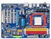
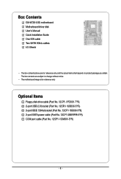
The box contents are for reference only. Box Contents GA-M720-US3 motherboard Motherboard driver disk User's Manual Quick Installation Guide One IDE cable Two SATA 3Gb/s cables I/O Shield • The box contents above are subject to change without notice. • The motherboard image is for reference only and the actual items shall depend on product package...
The box contents are for reference only. Box Contents GA-M720-US3 motherboard Motherboard driver disk User's Manual Quick Installation Guide One IDE cable Two SATA 3Gb/s cables I/O Shield • The box contents above are subject to change without notice. • The motherboard image is for reference only and the actual items shall depend on product package...
Manual
Page 9
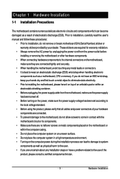
..., keep your dealer. These stickers are required for warranty validation. • Always remove the AC power by unplugging the power cord from the motherboard, make sure the power supply has been turned off. • Before turning on the power, make sure the power supply voltage has been ...components which can lead to damage to system components as well as physical harm to the user. • If you do not remove or break motherboard S/N (Serial Number) sticker or warranty sticker provided by your hands dry and first touch a metal object to eliminate static electricity. • Prior...
..., keep your dealer. These stickers are required for warranty validation. • Always remove the AC power by unplugging the power cord from the motherboard, make sure the power supply has been turned off. • Before turning on the power, make sure the power supply voltage has been ...components which can lead to damage to system components as well as physical harm to the user. • If you do not remove or break motherboard S/N (Serial Number) sticker or warranty sticker provided by your hands dry and first touch a metal object to eliminate static electricity. • Prior...
Manual
Page 10
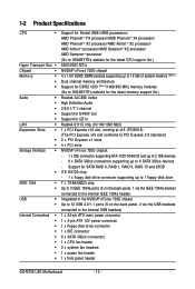
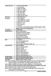
...drive connector 1 x IDE connector 6 x SATA 3Gb/s connectors 1 x CPU fan header 2 x system fan headers 1 x power fan header 1 x front panel header GA-M720-US3 Motherboard - 10 - 1-2 Product Specifications CPU Hyper Transport Bus Chipset Memory Audio ... (Note 1) Dual channel memory architecture Support for DDR2 1200 (Note 2)/1066/800 MHz memory modules (Go to GIGABYTE's website for the latest memory support list.) Realtek ALC888 codec High Definition Audio 2/4/5.1/7.1-channel Support for S/PDIF Out ...
...drive connector 1 x IDE connector 6 x SATA 3Gb/s connectors 1 x CPU fan header 2 x system fan headers 1 x power fan header 1 x front panel header GA-M720-US3 Motherboard - 10 - 1-2 Product Specifications CPU Hyper Transport Bus Chipset Memory Audio ... (Note 1) Dual channel memory architecture Support for DDR2 1200 (Note 2)/1066/800 MHz memory modules (Go to GIGABYTE's website for the latest memory support list.) Realtek ALC888 codec High Definition Audio 2/4/5.1/7.1-channel Support for S/PDIF Out ...
Manual
Page 11
... CPU/System fan speed control function is supported will depend on the CPU/System cooler you install. (Note 4) Available functions in EasyTune may differ by motherboard model. (Note 5) Due to the hardware limitation, you must install the AMD AM2+ PhenomTM Series CPU to enable support for Easy Energy Saver. - 11...
... CPU/System fan speed control function is supported will depend on the CPU/System cooler you install. (Note 4) Available functions in EasyTune may differ by motherboard model. (Note 5) Due to the hardware limitation, you must install the AMD AM2+ PhenomTM Series CPU to enable support for Easy Energy Saver. - 11...
Manual
Page 12
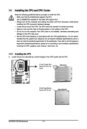
...Apply an even and thin layer of thermal grease on the computer if the CPU cooler is not recom- mended that the motherboard supports the CPU. (Go to GIGABYTE's website for the peripherals. The CPU cannot be set the frequency beyond hardware specifications since it does not meet the standard ...• Locate the pin one (denoted by a small triangle) of the Socket AM2 Socket A Small Triangle Marking Denotes CPU Pin One AM2+/AM2 CPU GA-M720-US3 Motherboard - 12 - Locate the pin one of the CPU. A Small Triangle Mark Denotes Pin One of the CPU socket and the CPU.
...Apply an even and thin layer of thermal grease on the computer if the CPU cooler is not recom- mended that the motherboard supports the CPU. (Go to GIGABYTE's website for the peripherals. The CPU cannot be set the frequency beyond hardware specifications since it does not meet the standard ...• Locate the pin one (denoted by a small triangle) of the Socket AM2 Socket A Small Triangle Marking Denotes CPU Pin One AM2+/AM2 CPU GA-M720-US3 Motherboard - 12 - Locate the pin one of the CPU. A Small Triangle Mark Denotes Pin One of the CPU socket and the CPU.
Manual
Page 13
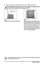
... socket, place one (small triangle marking) with the triangle mark on the middle of the CPU, lowering the locking lever and latching it into the motherboard CPU socket. Follow the steps below to the CPU. Before installing the CPU, make sure to turn off the computer and unplug the power cord...
... socket, place one (small triangle marking) with the triangle mark on the middle of the CPU, lowering the locking lever and latching it into the motherboard CPU socket. Follow the steps below to the CPU. Before installing the CPU, make sure to turn off the computer and unplug the power cord...
Manual
Page 14
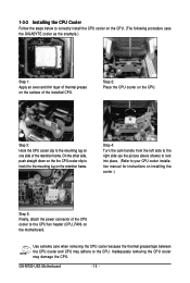
.... (The following procedure uses the GIGABYTE cooler as the picture above shows) to lock into place. (Refer to your CPU cooler installation manual for instructions on installing the cooler.) Step 5: Finally, attach the power connector of the CPU cooler to the CPU fan header (CPU_FAN) on the motherboard. GA-M720-US3 Motherboard - 14 - Step 4: Turn the...
.... (The following procedure uses the GIGABYTE cooler as the picture above shows) to lock into place. (Refer to your CPU cooler installation manual for instructions on installing the cooler.) Step 5: Finally, attach the power connector of the CPU cooler to the CPU fan header (CPU_FAN) on the motherboard. GA-M720-US3 Motherboard - 14 - Step 4: Turn the...
Manual
Page 15
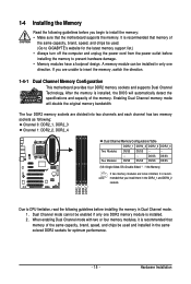
A memory module can be used . (Go to GIGABYTE's website for optimum performance. - 15 - If you install them... DDR2_2 DDR2_3 DDR2_4 Due to insert the memory, switch the direction. 1-4-1 Dual Channel Memory Configuration This motherboard provides four DDR2 memory sockets and supports Dual Channel Technology. DS/SS DS/SS Four Modules DS/SS...memory modules, it is recommended that memory of the memory. Hardware Installation It is recommended that the motherboard supports the memory. 1-4 Installing the Memory Read the following guidelines before you begin to install the memory...
A memory module can be used . (Go to GIGABYTE's website for optimum performance. - 15 - If you install them... DDR2_2 DDR2_3 DDR2_4 Due to insert the memory, switch the direction. 1-4-1 Dual Channel Memory Configuration This motherboard provides four DDR2 memory sockets and supports Dual Channel Technology. DS/SS DS/SS Four Modules DS/SS...memory modules, it is recommended that memory of the memory. Hardware Installation It is recommended that the motherboard supports the memory. 1-4 Installing the Memory Read the following guidelines before you begin to install the memory...
Manual
Page 16
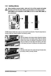
... DDR2 DIMM A DDR2 memory module has a notch, so it vertically into place when the memory module is securely inserted. Place the memory module on this motherboard. GA-M720-US3 Motherboard - 16 - DDR2 DIMMs are not compatible to DDR DIMMs. Be sure to install DDR2 DIMMs on the socket. As indicated in the picture on the...
... DDR2 DIMM A DDR2 memory module has a notch, so it vertically into place when the memory module is securely inserted. Place the memory module on this motherboard. GA-M720-US3 Motherboard - 16 - DDR2 DIMMs are not compatible to DDR DIMMs. Be sure to install DDR2 DIMMs on the socket. As indicated in the picture on the...
Manual
Page 17
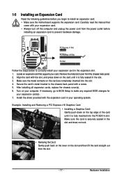
... expansion slot. 1. Hardware Installation Remove the metal slot cover from the power outlet before you begin to install an expansion card: • Make sure the motherboard supports the expansion card. Make sure the metal contacts on the top edge of the card until it is securely seated in your expansion card...
... expansion slot. 1. Hardware Installation Remove the metal slot cover from the power outlet before you begin to install an expansion card: • Make sure the motherboard supports the expansion card. Make sure the metal contacts on the top edge of the card until it is securely seated in your expansion card...
Manual
Page 18
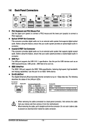
... drive and etc. USB Port The USB port supports the USB 2.0/1.1 specification. Use this feature, ensure that your device and then remove it from the motherboard. • When removing the cable, pull it side to side to an external audio system that supports digital coaxial audio. Optical S/PDIF Out Connector This... audio. Before using this port for an IEEE 1394a device. Use this feature, ensure that your audio system provides an optical digital audio in connector. GA-M720-US3 Motherboard - 18 -
... drive and etc. USB Port The USB port supports the USB 2.0/1.1 specification. Use this feature, ensure that your device and then remove it from the motherboard. • When removing the cable, pull it side to side to an external audio system that supports digital coaxial audio. Optical S/PDIF Out Connector This... audio. Before using this port for an IEEE 1394a device. Use this feature, ensure that your audio system provides an optical digital audio in connector. GA-M720-US3 Motherboard - 18 -
Manual
Page 20
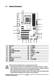
... 12) F_AUDIO 13) CD_IN 14) SPDIF_O 15) F_USB1 / F_USB2 16) F1_1394 17) COM 18) CI 19) CLR_CMOS Read the following guidelines before turning on the motherboard. GA-M720-US3 Motherboard - 20 -
... 12) F_AUDIO 13) CD_IN 14) SPDIF_O 15) F_USB1 / F_USB2 16) F1_1394 17) COM 18) CI 19) CLR_CMOS Read the following guidelines before turning on the motherboard. GA-M720-US3 Motherboard - 20 -
Manual
Page 21
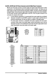
Before connecting the power connector, first make sure the power supply is turned off and all the components on the motherboard. The 12V power connector mainly supplies power to the power connector in the correct orientation. Do not insert the power supply cable into pins under... the protective cover when using a 2x12 power supply, remove the protective cover from the main power connector on the motherboard. 1/2) ATX_12V/ATX (2x2 12V Power Connector and 2x12 Main Power Connector) With the use of the power connector, the power supply can withstand high ...
Before connecting the power connector, first make sure the power supply is turned off and all the components on the motherboard. The 12V power connector mainly supplies power to the power connector in the correct orientation. Do not insert the power supply cable into pins under... the protective cover when using a 2x12 power supply, remove the protective cover from the main power connector on the motherboard. 1/2) ATX_12V/ATX (2x2 12V Power Connector and 2x12 Main Power Connector) With the use of the power connector, the power supply can withstand high ...
Manual
Page 22
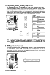
3/4/5) CPU_FAN/SYS_FAN1/SYS_FAN2/PWR_FAN (Fan Headers) The motherboard has a 4-pin CPU fan header (CPU_FAN), a 3-pin (SYS_FAN2) and a 4-pin (SYS_FAN1) system fan headers, and a 3-pin power fan ...: Pin No. 1 2 3 4 Definition GND +12V / Speed Control Sense Reserve 1 PWR_FAN 1 SYS_FAN2 SYS_FAN2/PWR_FAN: Pin No. The motherboard supports CPU fan speed control, which requires the use of the connector and the floppy disk drive cable. The pin 1 of the cable is... prevent your CPU and system from overheating. The types of different color. 33 1 34 2 GA-M720-US3 Motherboard - 22 -
3/4/5) CPU_FAN/SYS_FAN1/SYS_FAN2/PWR_FAN (Fan Headers) The motherboard has a 4-pin CPU fan header (CPU_FAN), a 3-pin (SYS_FAN2) and a 4-pin (SYS_FAN1) system fan headers, and a 3-pin power fan ...: Pin No. 1 2 3 4 Definition GND +12V / Speed Control Sense Reserve 1 PWR_FAN 1 SYS_FAN2 SYS_FAN2/PWR_FAN: Pin No. The motherboard supports CPU fan speed control, which requires the use of the connector and the floppy disk drive cable. The pin 1 of the cable is... prevent your CPU and system from overheating. The types of different color. 33 1 34 2 GA-M720-US3 Motherboard - 22 -
Manual
Page 24
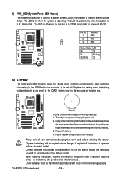
... if you are not able to replace the battery by removing the battery: 1. Gently remove the battery from the battery holder and wait for 5 seconds.) 3. GA-M720-US3 Motherboard - 24 - Definition 1 MPD+ 2 MPD- 3 MPD- 1 System Status LED S0 On S1 Blinking S3/S4/S5 Off 10) BATTERY The battery provides power to keep the...
... if you are not able to replace the battery by removing the battery: 1. Gently remove the battery from the battery holder and wait for 5 seconds.) 3. GA-M720-US3 Motherboard - 24 - Definition 1 MPD+ 2 MPD- 3 MPD- 1 System Status LED S0 On S1 Blinking S3/S4/S5 Off 10) BATTERY The battery provides power to keep the...
Manual
Page 26
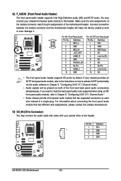
Incorrect connection between the module connector and the motherboard header will be present on both of the front and back panel audio connections simultaneously. For information about connecting the front panel audio module that ... front panel audio header supports HD audio by default. If your optical drive to the instructions on each wire instead of the motherboard header. Definition 1 CD-L 1 2 GND 3 GND 4 CD-R GA-M720-US3 Motherboard - 26 - If you want to mute the back panel audio (only supported when using an HD front panel audio module), refer to...
Incorrect connection between the module connector and the motherboard header will be present on both of the front and back panel audio connections simultaneously. For information about connecting the front panel audio module that ... front panel audio header supports HD audio by default. If your optical drive to the instructions on each wire instead of the motherboard header. Definition 1 CD-L 1 2 GND 3 GND 4 CD-R GA-M720-US3 Motherboard - 26 - If you want to mute the back panel audio (only supported when using an HD front panel audio module), refer to...


