Manual
Page 1
GA-M68SM-S2 AM2 socket motherboard for AMD AthlonTM 64 FX processor/ AMD AthlonTM 64 X2 Dual-Core processor/ AMD AthlonTM 64 processor/AMD SempronTM processor User's Manual Rev. 1002 12ME-M68SMS2-1002R * The WEEE marking on the product indicates this product must not be disposed of with user's other household waste and must be handed over to a designated collection point for the recycling of waste electrical and electronic equipment!! * The WEEE marking applies only in European Union's member states.
GA-M68SM-S2 AM2 socket motherboard for AMD AthlonTM 64 FX processor/ AMD AthlonTM 64 X2 Dual-Core processor/ AMD AthlonTM 64 processor/AMD SempronTM processor User's Manual Rev. 1002 12ME-M68SMS2-1002R * The WEEE marking on the product indicates this product must not be disposed of with user's other household waste and must be handed over to a designated collection point for the recycling of waste electrical and electronic equipment!! * The WEEE marking applies only in European Union's member states.

Manual
Page 2
Motherboard GA-M68SM-S2 Jul. 27, 2007 Motherboard GA-M68SM-S2 Jul. 27, 2007
Motherboard GA-M68SM-S2 Jul. 27, 2007 Motherboard GA-M68SM-S2 Jul. 27, 2007
Manual
Page 3
...instructions on how to the specifications and features in the use GIGABYTE's unique features, read or download the information on/from the Support\Motherboard\Technology Guide page on your motherboard revision before updating motherboard BIOS, drivers, or when looking for technical information. Documentation ...manual may be made by GIGA-BYTE TECHNOLOGY CO., LTD as the exclu- Changes to use of the motherboard is designated by GIGABYTE without GIGABYTE's prior written permission. All rights reserved. No part of this manual may be reproduced, copied, translated, ...
...instructions on how to the specifications and features in the use GIGABYTE's unique features, read or download the information on/from the Support\Motherboard\Technology Guide page on your motherboard revision before updating motherboard BIOS, drivers, or when looking for technical information. Documentation ...manual may be made by GIGA-BYTE TECHNOLOGY CO., LTD as the exclu- Changes to use of the motherboard is designated by GIGABYTE without GIGABYTE's prior written permission. All rights reserved. No part of this manual may be reproduced, copied, translated, ...
Manual
Page 4
Table of Contents Box Contents ...6 OptionalItems ...6 GA-M68SM-S2 Motherboard Layout 7 Block Diagram ...8 Chapter 1 Hardware Installation 9 1-1 Installation Precautions 9 1-2 Product Specifications 10 1-3 Installing the CPU and CPU Cooler 13 1-3-1 Installing the CPU 13 1-3-2 Installing the CPU ...
Table of Contents Box Contents ...6 OptionalItems ...6 GA-M68SM-S2 Motherboard Layout 7 Block Diagram ...8 Chapter 1 Hardware Installation 9 1-1 Installation Precautions 9 1-2 Product Specifications 10 1-3 Installing the CPU and CPU Cooler 13 1-3-1 Installing the CPU 13 1-3-2 Installing the CPU ...
Manual
Page 6
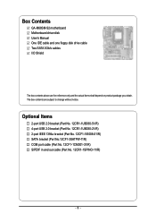
... (Part No.12CF1-3SATPW-11R) COM port cable (Part No. 12CF1-1CM001-31/R) S/PDIF in and out cable (Part No. 12CR1-1SPINO-11/R) - 6 - Box Contents GA-M68SM-S2 motherboard Motherboard driver disk User's Manual One IDE cable and one floppy disk drive cable Two SATA 3Gb/s cables I/O Shield The box contents above are subject to...
... (Part No.12CF1-3SATPW-11R) COM port cable (Part No. 12CF1-1CM001-31/R) S/PDIF in and out cable (Part No. 12CR1-1SPINO-11/R) - 6 - Box Contents GA-M68SM-S2 motherboard Motherboard driver disk User's Manual One IDE cable and one floppy disk drive cable Two SATA 3Gb/s cables I/O Shield The box contents above are subject to...
Manual
Page 7
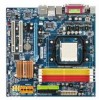
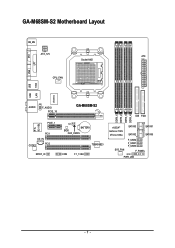
GA-M68SM-S2 Motherboard Layout KB_MS ATX_12V ATX Socket AM2 CPU_FAN DVI LPT VGA USB USB LAN 1394 IT8716 AUDIO F_AUDIO PCIE_16 PCIE_1 RTL 8211BL PCI1 CD_IN CODEC PCI2 SPDIF_IO GA-M68SM-S2 CI BATTERY BIOS CLR_CMOS COM F1_1394 TSB43AB23 DDRII_1 DDRII_2 DDRII_3 DDRII_4 IDE FDD nVIDIA® GeForce 7025/ nForce 630a SYS_FAN SATAII3 SATAII1 SATAII2 SATAII0 F_USB2 F_USB1 F_USB3 F_PANEL PWR_LED - 7 -
GA-M68SM-S2 Motherboard Layout KB_MS ATX_12V ATX Socket AM2 CPU_FAN DVI LPT VGA USB USB LAN 1394 IT8716 AUDIO F_AUDIO PCIE_16 PCIE_1 RTL 8211BL PCI1 CD_IN CODEC PCI2 SPDIF_IO GA-M68SM-S2 CI BATTERY BIOS CLR_CMOS COM F1_1394 TSB43AB23 DDRII_1 DDRII_2 DDRII_3 DDRII_4 IDE FDD nVIDIA® GeForce 7025/ nForce 630a SYS_FAN SATAII3 SATAII1 SATAII2 SATAII0 F_USB2 F_USB1 F_USB3 F_PANEL PWR_LED - 7 -
Manual
Page 9
These stickers are required for warranty validation. • Always remove the AC power by unplugging the power cord from the motherboard, make sure the power supply has been turned off. • Before turning on the computer power during the installation process can... become damaged as a result of electrostatic discharge (ESD). If you are connected tightly and securely. • When handling the motherboard, avoid touching any installation steps or have it on top of an antistatic pad or within a electrostatic shielding container. • Before unplugging the...
These stickers are required for warranty validation. • Always remove the AC power by unplugging the power cord from the motherboard, make sure the power supply has been turned off. • Before turning on the computer power during the installation process can... become damaged as a result of electrostatic discharge (ESD). If you are connected tightly and securely. • When handling the motherboard, avoid touching any installation steps or have it on top of an antistatic pad or within a electrostatic shielding container. • Before unplugging the...
Manual
Page 10
... GeForce 7025/nForce 630a chipset Š Up to 10 USB 2.0/1.1 ports (4 on the back panel, 6 via the USB brackets connected to the internal USB headers) GA-M68SM-S2 Motherboard - 10 - Support for CD In Š RTL 8211BL chip (10/100/1000 Mbit) Š 1 x PCI Express x16 slot Š 1 x PCI Express...16 GB of system memory (Note 1) Š Dual channel memory architecture Š Support for DDR2 800/667/533 MHz memory modules (Go to GIGABYTE's website for the latest memory support list.) Š Realtek ALC888 codec Š High Definition Audio Š 2/4/5.1/7.1-channel Š Support for S/...
... GeForce 7025/nForce 630a chipset Š Up to 10 USB 2.0/1.1 ports (4 on the back panel, 6 via the USB brackets connected to the internal USB headers) GA-M68SM-S2 Motherboard - 10 - Support for CD In Š RTL 8211BL chip (10/100/1000 Mbit) Š 1 x PCI Express x16 slot Š 1 x PCI Express...16 GB of system memory (Note 1) Š Dual channel memory architecture Š Support for DDR2 800/667/533 MHz memory modules (Go to GIGABYTE's website for the latest memory support list.) Š Realtek ALC888 codec Š High Definition Audio Š 2/4/5.1/7.1-channel Š Support for S/...
Manual
Page 12
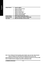
GA-M68SM-S2 Motherboard - 12 - English Unique Features Bundled Software Operating System Form Factor Š Support for @BIOS Š Support for Download Center Š Support for Q-Flash Š Support .... (Note 2) Whether the CPU fan speed control function is supported will depend on the CPU you install. (Note 3) Available functions in Easytune may differ by motherboard model.
GA-M68SM-S2 Motherboard - 12 - English Unique Features Bundled Software Operating System Form Factor Š Support for @BIOS Š Support for Download Center Š Support for Q-Flash Š Support .... (Note 2) Whether the CPU fan speed control function is supported will depend on the CPU you install. (Note 3) Available functions in Easytune may differ by motherboard model.
Manual
Page 13
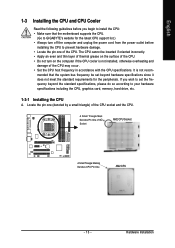
... prevent hardware damage. • Locate the pin one (denoted by a small triangle) of the CPU socket and the CPU. mended that the motherboard supports the CPU. (Go to GIGABYTE's website for the peripherals. It is not installed, otherwise overheating and damage of the Socket AM2 CPU Socket A Small Triangle Marking Denotes CPU...
... prevent hardware damage. • Locate the pin one (denoted by a small triangle) of the CPU socket and the CPU. mended that the motherboard supports the CPU. (Go to GIGABYTE's website for the peripherals. It is not installed, otherwise overheating and damage of the Socket AM2 CPU Socket A Small Triangle Marking Denotes CPU...
Manual
Page 14
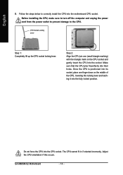
..., place one (small triangle marking) with the triangle mark on the middle of the CPU, lowering the locking lever and latching it into the motherboard CPU socket. GA-M68SM-S2 Motherboard - 14 - Follow the steps below to the CPU. Adjust the CPU orientation if this occurs. Make sure that the CPU pins fit perfectly into...
..., place one (small triangle marking) with the triangle mark on the middle of the CPU, lowering the locking lever and latching it into the motherboard CPU socket. GA-M68SM-S2 Motherboard - 14 - Follow the steps below to the CPU. Adjust the CPU orientation if this occurs. Make sure that the CPU pins fit perfectly into...
Manual
Page 15
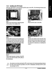
Step 3: Hook the CPU cooler clip to the mounting lug on the motherboard. Step 4: Turn the cam handle from the left side to the right side (as the example.) Step 1: Apply an even and thin layer of thermal ... the CPU. English 1-3-2 Installing the CPU Cooler Follow the steps below to correctly install the CPU cooler on the CPU. (The following procedure uses the GIGABYTE cooler as the picture above shows) to lock into place. (Refer to your CPU cooler installation manual for instructions on installing the cooler.) Step 5: Finally...
Step 3: Hook the CPU cooler clip to the mounting lug on the motherboard. Step 4: Turn the cam handle from the left side to the right side (as the example.) Step 1: Apply an even and thin layer of thermal ... the CPU. English 1-3-2 Installing the CPU Cooler Follow the steps below to correctly install the CPU cooler on the CPU. (The following procedure uses the GIGABYTE cooler as the picture above shows) to lock into place. (Refer to your CPU cooler installation manual for instructions on installing the cooler.) Step 5: Finally...
Manual
Page 16
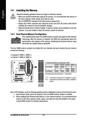
GA-M68SM-S2 Motherboard - 16 - The four DDR2 memory sockets are to CPU limitation, read...brand, speed, and chips be used and installed in only one DDR2 memory module is recommended that the motherboard supports the memory. Dual Channel mode cannot be installed, it is recommended that memory of the memory. DDRII_1...DDRII_3 DDRII_4 Two Modules DS/SS DS/SS - - - - - - - - A memory module can be used . (Go to GIGABYTE's website for optimum performance. English 1-4 Installing the Memory Read the following guidelines before you begin to install the memory: • Make sure...
GA-M68SM-S2 Motherboard - 16 - The four DDR2 memory sockets are to CPU limitation, read...brand, speed, and chips be used and installed in only one DDR2 memory module is recommended that the motherboard supports the memory. Dual Channel mode cannot be installed, it is recommended that memory of the memory. DDRII_1...DDRII_3 DDRII_4 Two Modules DS/SS DS/SS - - - - - - - - A memory module can be used . (Go to GIGABYTE's website for optimum performance. English 1-4 Installing the Memory Read the following guidelines before you begin to install the memory: • Make sure...
Manual
Page 17
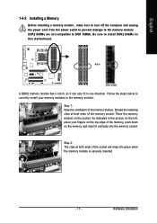
... in the memory sockets. As indicated in the picture on the left, place your memory modules in one direction. Place the memory module on this motherboard. Follow the steps below to the memory module. Hardware Installation DDR2 DIMMs are not compatible to DDR DIMMs. Be sure to install DDR2 DIMMs on...
... in the memory sockets. As indicated in the picture on the left, place your memory modules in one direction. Place the memory module on this motherboard. Follow the steps below to the memory module. Hardware Installation DDR2 DIMMs are not compatible to DDR DIMMs. Be sure to install DDR2 DIMMs on...
Manual
Page 18
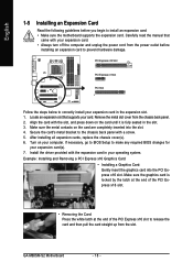
... cord from the power outlet before you begin to install an expansion card: • Make sure the motherboard supports the expansion card. Make sure the graphics card is fully seated in the expansion slot. 1. GA-M68SM-S2 Motherboard - 18 - Remove the metal slot cover from the slot. Secure the card's metal bracket to the chassis...
... cord from the power outlet before you begin to install an expansion card: • Make sure the motherboard supports the expansion card. Make sure the graphics card is fully seated in the expansion slot. 1. GA-M68SM-S2 Motherboard - 18 - Remove the metal slot cover from the slot. Secure the card's metal bracket to the chassis...
Manual
Page 19
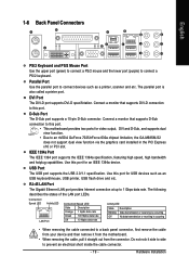
.... Do not rock it side to side to a back panel connector, first remove the cable from your device and then remove it from the motherboard. • When removing the cable, pull it straight out from the connector. Connection/ Speed LED Activity LED LAN Port Connection/Speed LED: State...the upper port (green) to connect a PS/2 mouse and the lower port (purple) to an nVIDIA GeForce 7025/nForce 630a chipset limitation, the GA-M68SM-S2 does not support dual view function via the graphics card installed in the PCI Express x16 or PCI slot. The parallel port is occurring •...
.... Do not rock it side to side to a back panel connector, first remove the cable from your device and then remove it from the motherboard. • When removing the cable, pull it straight out from the connector. Connection/ Speed LED Activity LED LAN Port Connection/Speed LED: State...the upper port (green) to connect a PS/2 mouse and the lower port (purple) to an nVIDIA GeForce 7025/nForce 630a chipset limitation, the GA-M68SM-S2 does not support dual view function via the graphics card installed in the PCI Express x16 or PCI slot. The parallel port is occurring •...
Manual
Page 20
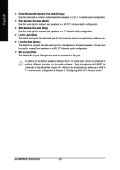
... Audio." Line Out Jack (Green) The default line out jack. Only microphones still MUST be used to connect center/subwoofer speakers in a 5.1/7.1-channel audio configuration. GA-M68SM-S2 Motherboard - 20 - Use this jack. Use this audio jack to connect front speakers in a 4/5.1/7.1-channel audio configuration. English Center/Subwoofer Speaker Out Jack (Orange) Use this...
... Audio." Line Out Jack (Green) The default line out jack. Only microphones still MUST be used to connect center/subwoofer speakers in a 5.1/7.1-channel audio configuration. GA-M68SM-S2 Motherboard - 20 - Use this jack. Use this audio jack to connect front speakers in a 4/5.1/7.1-channel audio configuration. English Center/Subwoofer Speaker Out Jack (Orange) Use this...
Manual
Page 21
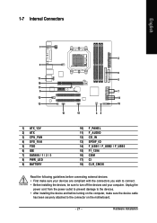
...) F_AUDIO 12) CD_IN 13) SPDIF_IO 14) F_USB1 / F_USB2 / F_USB3 15) F1_1394 16) COM 17) CI 18) CLR_CMOS Read the following guidelines before turning on the motherboard. - 21 - Hardware Installation
...) F_AUDIO 12) CD_IN 13) SPDIF_IO 14) F_USB1 / F_USB2 / F_USB3 15) F1_1394 16) COM 17) CI 18) CLR_CMOS Read the following guidelines before turning on the motherboard. - 21 - Hardware Installation
Manual
Page 22
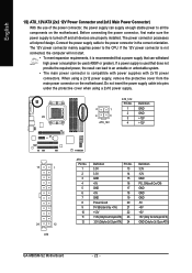
... -12V GND PS_ON(soft On/Off) GND GND GND -5V +5V +5V +5V (Only for 2x12-pin ATX) GND (Only for 2x12-pin ATX) GA-M68SM-S2 Motherboard - 22 - Connect the power supply cable to the CPU. If the 12V power connector is not connected, the computer will not start. • To meet...power supplies with 2x10 power connectors. The power connector possesses a foolproof design. If a power supply is turned off and all the components on the motherboard. Do not insert the power supply cable into pins under the protective cover when using a 2x12 power supply, remove the protective cover from the ...
... -12V GND PS_ON(soft On/Off) GND GND GND -5V +5V +5V +5V (Only for 2x12-pin ATX) GND (Only for 2x12-pin ATX) GA-M68SM-S2 Motherboard - 22 - Connect the power supply cable to the CPU. If the 12V power connector is not connected, the computer will not start. • To meet...power supplies with 2x10 power connectors. The power connector possesses a foolproof design. If a power supply is turned off and all the components on the motherboard. Do not insert the power supply cable into pins under the protective cover when using a 2x12 power supply, remove the protective cover from the ...
Manual
Page 23
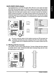
... drive. Do not place a jumper cap on the connector. 34 33 2 1 - 23 - Hardware Installation English 3/4) CPU_FAN/SYS_FAN (Fan Headers) The motherboard has a 4-pin CPU fan header (CPU_FAN) and a 3-pin system fan header (SYS_FAN). CPU_FAN: Pin No. The types of a CPU fan with ... and requires a +12V voltage. For optimum heat dissipation, it in damage to prevent your CPU and system from overheating. The motherboard supports CPU fan speed control, which requires the use of floppy disk drives supported are not configuration jumper blocks. Each fan header supplies...
... drive. Do not place a jumper cap on the connector. 34 33 2 1 - 23 - Hardware Installation English 3/4) CPU_FAN/SYS_FAN (Fan Headers) The motherboard has a 4-pin CPU fan header (CPU_FAN) and a 3-pin system fan header (SYS_FAN). CPU_FAN: Pin No. The types of a CPU fan with ... and requires a +12V voltage. For optimum heat dissipation, it in damage to prevent your CPU and system from overheating. The motherboard supports CPU fan speed control, which requires the use of floppy disk drives supported are not configuration jumper blocks. Each fan header supplies...


