Manual
Page 4
... ...6 GA-M68SM-S2 Motherboard Layout 7 Block Diagram ...8 Chapter 1 Hardware Installation 9 1-1 Installation Precautions 9 1-2 Product Specifications 10 1-3 Installing the CPU and CPU Cooler 13 1-3-1 Installing the CPU 13 1-3-2 Installing the CPU Cooler 15 1-4 Installing the Memory 16 1-4-1 Dual Channel Memory Configuration 16 1-4-2 Installing a Memory 17 1-5 Installing an Expansion Card 18 1-6 Back Panel Connectors 19 1-7 Internal Connectors 21 Chapter 2 BIOS Setup 31 2-1 Startup Screen 32 2-2 The Main Menu 33 2-3 Standard CMOS Features 35 2-4 Advanced BIOS Features...
... ...6 GA-M68SM-S2 Motherboard Layout 7 Block Diagram ...8 Chapter 1 Hardware Installation 9 1-1 Installation Precautions 9 1-2 Product Specifications 10 1-3 Installing the CPU and CPU Cooler 13 1-3-1 Installing the CPU 13 1-3-2 Installing the CPU Cooler 15 1-4 Installing the Memory 16 1-4-1 Dual Channel Memory Configuration 16 1-4-2 Installing a Memory 17 1-5 Installing an Expansion Card 18 1-6 Back Panel Connectors 19 1-7 Internal Connectors 21 Chapter 2 BIOS Setup 31 2-1 Startup Screen 32 2-2 The Main Menu 33 2-3 Standard CMOS Features 35 2-4 Advanced BIOS Features...
Manual
Page 10
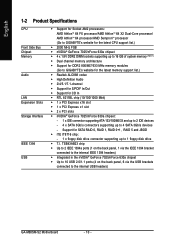
... 7025/nForce 630a chipset Š Up to 10 USB 2.0/1.1 ports (4 on the back panel, 6 via the USB brackets connected to 1 floppy disk drive Š T.I. Support for CD In Š RTL 8211BL chip (10/100/1000 Mbit) Š 1 x PCI Express x16 slot Š 1 x PCI Express x1 slot Š 2 x PCI slots Š nVIDIA® GeForce 7025/nForce 630a chipset: - 1 x IDE connector supporting ATA-133/100/66/33 and up to 2 IDE devices - 4 x SATA 3Gb/s connectors supporting up to the internal USB headers) GA-M68SM-S2 Motherboard - 10 -
... 7025/nForce 630a chipset Š Up to 10 USB 2.0/1.1 ports (4 on the back panel, 6 via the USB brackets connected to 1 floppy disk drive Š T.I. Support for CD In Š RTL 8211BL chip (10/100/1000 Mbit) Š 1 x PCI Express x16 slot Š 1 x PCI Express x1 slot Š 2 x PCI slots Š nVIDIA® GeForce 7025/nForce 630a chipset: - 1 x IDE connector supporting ATA-133/100/66/33 and up to 2 IDE devices - 4 x SATA 3Gb/s connectors supporting up to the internal USB headers) GA-M68SM-S2 Motherboard - 10 -
Manual
Page 16
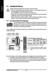
After the memory is installed, the BIOS will double the original memory bandwidth. Enabling Dual Channel memory mode will automatically detect the specifications and capacity of the memory. DDRII_1 DDRII_2 DDRII_3 DDRII_4 Due to insert the memory, switch the direction. 1-4-1 Dual Channel Memory Configuration This motherboard provides four DDR2 memory sockets and supports Dual Channel Technology. GA-M68SM-S2 Motherboard - 16 - DS/SS DS/SS Four Modules DS/SS DS/SS DS/SS DS/SS (SS=Single-Sided, DS...
After the memory is installed, the BIOS will double the original memory bandwidth. Enabling Dual Channel memory mode will automatically detect the specifications and capacity of the memory. DDRII_1 DDRII_2 DDRII_3 DDRII_4 Due to insert the memory, switch the direction. 1-4-1 Dual Channel Memory Configuration This motherboard provides four DDR2 memory sockets and supports Dual Channel Technology. GA-M68SM-S2 Motherboard - 16 - DS/SS DS/SS Four Modules DS/SS DS/SS DS/SS DS/SS (SS=Single-Sided, DS...
Manual
Page 18
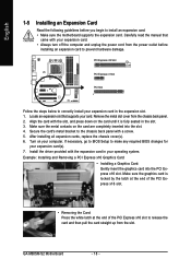
... card. Carefully read the manual that supports your expansion card. • Always turn off the computer and unplug the power cord from the power outlet before you begin to release the card and then pull the card straight up from the chassis back panel. 2. If necessary, go to BIOS Setup to correctly install your computer. Example: Installing and Removing a PCI Express x16 Graphics Card: • Installing a Graphics Card: Gently insert the graphics card into the slot. 4. GA-M68SM-S2 Motherboard...
... card. Carefully read the manual that supports your expansion card. • Always turn off the computer and unplug the power cord from the power outlet before you begin to release the card and then pull the card straight up from the chassis back panel. 2. If necessary, go to BIOS Setup to correctly install your computer. Example: Installing and Removing a PCI Express x16 Graphics Card: • Installing a Graphics Card: Gently insert the graphics card into the slot. 4. GA-M68SM-S2 Motherboard...
Manual
Page 19
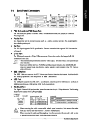
... speed, high bandwidth and hotplug capabilities. USB Port The USB port supports the USB 2.0/1.1 specification. Connect a monitor that supports D-Sub connection to an nVIDIA GeForce 7025/nForce 630a chipset limitation, the GA-M68SM-S2 does not support dual view function via the graphics card installed in the PCI Express x16 or PCI slot. Do not rock it straight out from the connector. Hardware Installation Use this port. • This motherboard provides two ports for USB devices such as a printer, scanner and etc. Connection/ Speed LED Activity LED LAN Port Connection/Speed...
... speed, high bandwidth and hotplug capabilities. USB Port The USB port supports the USB 2.0/1.1 specification. Connect a monitor that supports D-Sub connection to an nVIDIA GeForce 7025/nForce 630a chipset limitation, the GA-M68SM-S2 does not support dual view function via the graphics card installed in the PCI Express x16 or PCI slot. Do not rock it straight out from the connector. Hardware Installation Use this port. • This motherboard provides two ports for USB devices such as a printer, scanner and etc. Connection/ Speed LED Activity LED LAN Port Connection/Speed...
Manual
Page 23
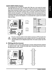
... headers. 5) FDD (Floppy Disk Drive Connector) This connector is recommended that a system fan be sure to prevent your CPU and system from overheating. Each fan header supplies a +12V power voltage and possesses a foolproof insertion design. The black connector wire is the ground wire. The types of a CPU fan with color-coded power connector wires. CPU_FAN: Pin No. English 3/4) CPU_FAN/SYS_FAN (Fan Headers) The motherboard has a 4-pin CPU fan header (CPU_FAN) and a 3-pin system fan header (SYS_FAN). When connecting a fan cable, be installed inside the chassis. Definition...
... headers. 5) FDD (Floppy Disk Drive Connector) This connector is recommended that a system fan be sure to prevent your CPU and system from overheating. Each fan header supplies a +12V power voltage and possesses a foolproof insertion design. The black connector wire is the ground wire. The types of a CPU fan with color-coded power connector wires. CPU_FAN: Pin No. English 3/4) CPU_FAN/SYS_FAN (Fan Headers) The motherboard has a 4-pin CPU fan header (CPU_FAN) and a 3-pin system fan header (SYS_FAN). When connecting a fan cable, be installed inside the chassis. Definition...
Manual
Page 26
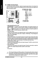
.... GA-M68SM-S2 Motherboard - 26 - PW+ PWSPEAK+ SPEAK- 2 20 1 19 HD+ HD- When connecting your system using the power switch (refer to Chapter 2, "BIOS Setup," "Power Management Setup," for information about beep codes. • HD (IDE Hard Drive Activity LED) Connects to the hard drive activity LED on the chassis front panel. If a problem is in S1 sleep state. A front panel module mainly consists of power switch, reset switch, power LED, hard drive activity LED, speaker and etc. English 10) F_PANEL (Front Panel Header) Connect the power switch, reset switch, speaker...
.... GA-M68SM-S2 Motherboard - 26 - PW+ PWSPEAK+ SPEAK- 2 20 1 19 HD+ HD- When connecting your system using the power switch (refer to Chapter 2, "BIOS Setup," "Power Management Setup," for information about beep codes. • HD (IDE Hard Drive Activity LED) Connects to the hard drive activity LED on the chassis front panel. If a problem is in S1 sleep state. A front panel module mainly consists of power switch, reset switch, power LED, hard drive activity LED, speaker and etc. English 10) F_PANEL (Front Panel Header) Connect the power switch, reset switch, speaker...
Manual
Page 30
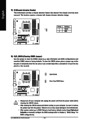
... to BIOS Setup to load factory defaults (select Load Optimized Defaults) or manually configure the BIOS settings (refer to clear the CMOS values (e.g. This function requires a chassis with chassis intrusion detection design. Definition 1 1 Signal 2 GND 18) CLR_CMOS (Clearing CMOS Jumper) Use this jumper to Chapter 2, "BIOS Setup," for a few seconds. Open: Normal Short: Clear CMOS Values • Always turn off your computer, be sure to remove the jumper cap from the jumper. GA-M68SM-S2 Motherboard - 30 - English 17) CI (Chassis Intrusion Header) This motherboard...
... to BIOS Setup to load factory defaults (select Load Optimized Defaults) or manually configure the BIOS settings (refer to clear the CMOS values (e.g. This function requires a chassis with chassis intrusion detection design. Definition 1 1 Signal 2 GND 18) CLR_CMOS (Clearing CMOS Jumper) Use this jumper to Chapter 2, "BIOS Setup," for a few seconds. Open: Normal Short: Clear CMOS Values • Always turn off your computer, be sure to remove the jumper cap from the jumper. GA-M68SM-S2 Motherboard - 30 - English 17) CI (Chassis Intrusion Header) This motherboard...
Manual
Page 35
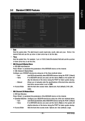
...no IDE/SATA devices are used , set the date. BIOS Setup Time Sets the system time. Access Mode Sets the hard drive access mode. Access Mode Sets the hard drive access mode. IDE Channel 0 Master/Slave Configure your IDE/SATA devices by using one of the IDE/SATA device on this channel. IDE Channel 2/3 Master/Slave IDE Auto-Detection Press to manually enter the specifications of the device during the POST for faster system startup. English 2-3 Standard CMOS Features Date (mm:dd:yy) Time (hh:mm:ss) CMOS Setup Utility-Copyright (C) 1984-2007 Award Software Standard...
...no IDE/SATA devices are used , set the date. BIOS Setup Time Sets the system time. Access Mode Sets the hard drive access mode. Access Mode Sets the hard drive access mode. IDE Channel 0 Master/Slave Configure your IDE/SATA devices by using one of the IDE/SATA device on this channel. IDE Channel 2/3 Master/Slave IDE Auto-Detection Press to manually enter the specifications of the device during the POST for faster system startup. English 2-3 Standard CMOS Features Date (mm:dd:yy) Time (hh:mm:ss) CMOS Setup Utility-Copyright (C) 1984-2007 Award Software Standard...
Manual
Page 37
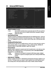
... a third party hardware monitor utility is installed. (Default: Disabled) - 37 - Use the up or down arrow key to select a hard drive, then press the plus key (or ) or the minus key (or ) to exit this item, set the password(s) under the Set Supervisor/User Password item in the BIOS Main Menu. Options are: Floppy, LS120, Hard Disk, CDROM, ZIP, USB-FDD, USB-ZIP, USB-CDROM, USB-HDD, Legacy LAN, Disabled. This feature allows your hard drive. After configuring this menu when finished. Use the up or...
... a third party hardware monitor utility is installed. (Default: Disabled) - 37 - Use the up or down arrow key to select a hard drive, then press the plus key (or ) or the minus key (or ) to exit this item, set the password(s) under the Set Supervisor/User Password item in the BIOS Main Menu. Options are: Floppy, LS120, Hard Disk, CDROM, ZIP, USB-FDD, USB-ZIP, USB-CDROM, USB-HDD, Legacy LAN, Disabled. This feature allows your hard drive. After configuring this menu when finished. Use the up or...
Manual
Page 38
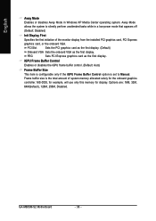
...Options are: 16M, 32M, 64M(default), 128M, 256M, Disabled. MS-DOS, for example, will use only this memory for the onboard graphics controller. PCI Slot Sets the PCI graphics card as the first display. (Default) Onboard VGA Sets the onboard VGA as the first display. GA-M68SM-S2 Motherboard - 38 - Away Mode allows the system to Manual. English Away Mode Enables or disables Away Mode in a low-power mode that appears off (Default: Disabled) Init Display First Specifies the first initiation of system memory allocated solely for display. PEG Sets PCI Express graphics...
...Options are: 16M, 32M, 64M(default), 128M, 256M, Disabled. MS-DOS, for example, will use only this memory for the onboard graphics controller. PCI Slot Sets the PCI graphics card as the first display. (Default) Onboard VGA Sets the onboard VGA as the first display. GA-M68SM-S2 Motherboard - 38 - Away Mode allows the system to Manual. English Away Mode Enables or disables Away Mode in a low-power mode that appears off (Default: Disabled) Init Display First Specifies the first initiation of system memory allocated solely for display. PEG Sets PCI Express graphics...
Manual
Page 40
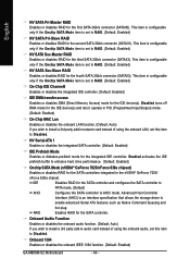
... storage driver to enhance hard drive performance. (Default: Enabled) Onchip SATA Mode (nVIDIA® GeForce 7025/nForce 630a chipset) Enables or disables RAID for the first SATA 3Gb/s connector (SATAII0). Disabled turns off DMA mode for the IDE device(s). Enabled activates the IDE prefetch buffer to enable advanced Serial ATA features such as Native Command Queuing and hot plug. Onboard Audio Function Enables or disables the onboard audio function. (Default: Auto) If you wish to install a 3rd party add-in network card instead of using the onboard LAN, set...
... storage driver to enhance hard drive performance. (Default: Enabled) Onchip SATA Mode (nVIDIA® GeForce 7025/nForce 630a chipset) Enables or disables RAID for the first SATA 3Gb/s connector (SATAII0). Disabled turns off DMA mode for the IDE device(s). Enabled activates the IDE prefetch buffer to enable advanced Serial ATA features such as Native Command Queuing and hot plug. Onboard Audio Function Enables or disables the onboard audio function. (Default: Auto) If you wish to install a 3rd party add-in network card instead of using the onboard LAN, set...
Manual
Page 42
... detect USB storage devices, including USB flash drives and USB hard drives during the POST. (Default: Enabled) GA-M68SM-S2 Motherboard - 42 - ECP Mode Use DMA Selects DMA channel for the onboard parallel (LPT) port. USB Keyboard Function Allows USB keyboard to be used in MS-DOS. (Default: Enabled) USB Mouse Function Allows USB mouse to be used in ECP mode. USB Controllers Enables or disables the integrated USB controller. (Default: Enabled) Disabled will turn off all of the USB functionalities below. Options are : 378/IRQ7 (default), 278/IRQ5, 3BC/IRQ7, Disabled. Options are : Auto...
... detect USB storage devices, including USB flash drives and USB hard drives during the POST. (Default: Enabled) GA-M68SM-S2 Motherboard - 42 - ECP Mode Use DMA Selects DMA channel for the onboard parallel (LPT) port. USB Keyboard Function Allows USB keyboard to be used in MS-DOS. (Default: Enabled) USB Mouse Function Allows USB mouse to be used in ECP mode. USB Controllers Enables or disables the integrated USB controller. (Default: Enabled) Disabled will turn off all of the USB functionalities below. Options are : 378/IRQ7 (default), 278/IRQ5, 3BC/IRQ7, Disabled. Options are : Auto...

Manual
Page 47
... CPU fan speed control function. You can adjust the fan speed with EasyTune based on system requirements. If disabled, CPU fan runs at different speed according to control CPU fan speed. Sets PWM mode for a 3-pin CPU fan. BIOS Setup Enabled allows the CPU fan to run at full speed. (Default: Enabled) CPU Smart FAN Mode Specifies how to the CPU temperature. This item is configurable only if CPU Smart FAN Control is set to Enabled. Auto Lets BIOS autodetect the type of CPU fan installed and sets the optimal CPU fan control mode. (Default) Voltage PWM Sets Voltage mode...
... CPU fan speed control function. You can adjust the fan speed with EasyTune based on system requirements. If disabled, CPU fan runs at different speed according to control CPU fan speed. Sets PWM mode for a 3-pin CPU fan. BIOS Setup Enabled allows the CPU fan to run at full speed. (Default: Enabled) CPU Smart FAN Mode Specifies how to the CPU temperature. This item is configurable only if CPU Smart FAN Control is set to Enabled. Auto Lets BIOS autodetect the type of CPU fan installed and sets the optimal CPU fan control mode. (Default) Voltage PWM Sets Voltage mode...
Manual
Page 67
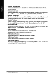
... want to AHCI or RAID mode. - 67 - English Chapter 5 Appendix 5-1 Configuring SATA Hard Drive(s) To configure SATA hard drive(s), follow the steps below: A. If you do not want to create RAID, you use two hard drives with identical model and capacity). Install SATA hard drive(s) in your computer. Installing SATA hard drive(s) in your computer Attach one hard drive. • An empty formatted floppy disk. • Windows Vista/XP/2000 setup disk. • Motherboard driver disk. 5-1-1 Configuring the Onboard SATA Controller A. Install the SATA RAID/AHCI driver and operating...
... want to AHCI or RAID mode. - 67 - English Chapter 5 Appendix 5-1 Configuring SATA Hard Drive(s) To configure SATA hard drive(s), follow the steps below: A. If you do not want to create RAID, you use two hard drives with identical model and capacity). Install SATA hard drive(s) in your computer. Installing SATA hard drive(s) in your computer Attach one hard drive. • An empty formatted floppy disk. • Windows Vista/XP/2000 setup disk. • Motherboard driver disk. 5-1-1 Configuring the Onboard SATA Controller A. Install the SATA RAID/AHCI driver and operating...
Manual
Page 72
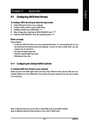
... drive (example: D:\>). GA-M68SM-S2 Motherboard Figure 3 - 72 - First of all, copy the driver for the SATA controller from the menu. For example, to install Windows XP (32-bit) onto the RAID drives, press to your system. Prepare a startup disk that has CD-ROM support and a blank formatted floppy disk. At the D:\> prompt, type the following two commands. Figure 1 Figure 2 (Note) For users without a startup disk: Use an alternative system and insert the motherboard driver disk...
... drive (example: D:\>). GA-M68SM-S2 Motherboard Figure 3 - 72 - First of all, copy the driver for the SATA controller from the menu. For example, to install Windows XP (32-bit) onto the RAID drives, press to your system. Prepare a startup disk that has CD-ROM support and a blank formatted floppy disk. At the D:\> prompt, type the following two commands. Figure 1 Figure 2 (Note) For users without a startup disk: Use an alternative system and insert the motherboard driver disk...
Manual
Page 73
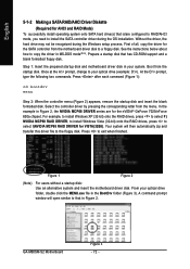
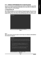
... required BIOS settings, you need to install a 3rd party SCSI or RAID driver" (Figure 1). Appendix Windows Setup Press F6 if you do not want to specify additional mass storage devices for use with Windows, including those for use with Windows, press ENTER. English 5-1-3 Installing the SATA RAID/AHCI Driver and Operating System Now that below appears, insert the floppy disk containing the SATA RAID/AHCI driver and press (Figure 2). Installing Windows XP Step 1: Restart your system to boot...
... required BIOS settings, you need to install a 3rd party SCSI or RAID driver" (Figure 1). Appendix Windows Setup Press F6 if you do not want to specify additional mass storage devices for use with Windows, including those for use with Windows, press ENTER. English 5-1-3 Installing the SATA RAID/AHCI Driver and Operating System Now that below appears, insert the floppy disk containing the SATA RAID/AHCI driver and press (Figure 2). Installing Windows XP Step 1: Restart your system to boot...
Manual
Page 74
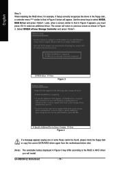
... adapters, CD-ROM drives, or special disk controllers for use with Windows, including those for which you have a device support disk from a mass storage device manufacturer, press S. * If you must press to select an additional driver. Windows Setup You have any device support disks from the motherboard driver disk. (Note) The selectable item(s) displayed in Figure 3. GA-M68SM-S2 Motherboard - 74 - English Step 3: When installing the RAID driver, for example, if Setup correctly recognizes the driver in the floppy disk, a controller menu (Note) similar...
... adapters, CD-ROM drives, or special disk controllers for use with Windows, including those for which you have a device support disk from a mass storage device manufacturer, press S. * If you must press to select an additional driver. Windows Setup You have any device support disks from the motherboard driver disk. (Note) The selectable item(s) displayed in Figure 3. GA-M68SM-S2 Motherboard - 74 - English Step 3: When installing the RAID driver, for example, if Setup correctly recognizes the driver in the floppy disk, a controller menu (Note) similar...
Manual
Page 78
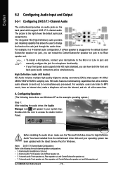
... speaker is plugged into the default Center/ Subwoofer speaker out jack, you can have an Internet chat, make sure the "Microsoft UAA Bus driver for High Definition Audio" has been installed from the motherboard driver disk and your operating system has been updated with the latest Service Pack for Windows. (Note) 2/4/5.1/7.1 Channel Audio Configurations: Refer to MP3 music, have both the front and back panel audio connectors active simultaneously. For example, users...
... speaker is plugged into the default Center/ Subwoofer speaker out jack, you can have an Internet chat, make sure the "Microsoft UAA Bus driver for High Definition Audio" has been installed from the motherboard driver disk and your operating system has been updated with the latest Service Pack for Windows. (Note) 2/4/5.1/7.1 Channel Audio Configurations: Refer to MP3 music, have both the front and back panel audio connectors active simultaneously. For example, users...
Manual
Page 85
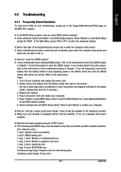
...the motherboard battery in Chapter 1 to short the jumper to enter BIOS Setup during the POST mean? If not, try a speaker with an internal amplifier. A: The following Award BIOS beep code descriptions may help you identify possible computer problems. (For reference only.) 1 short: System boots successfully 2 short: CMOS setting error 1 long, 1 short: Memory or motherboard error 1 long, 2 short: Monitor or graphics card error 1 long, 3 short: Keyboard error 1 long, 9 short: BIOS ROM error Continuous long beeps: Graphics card not inserted properly Continuous short beeps: Power error - 85...
...the motherboard battery in Chapter 1 to short the jumper to enter BIOS Setup during the POST mean? If not, try a speaker with an internal amplifier. A: The following Award BIOS beep code descriptions may help you identify possible computer problems. (For reference only.) 1 short: System boots successfully 2 short: CMOS setting error 1 long, 1 short: Memory or motherboard error 1 long, 2 short: Monitor or graphics card error 1 long, 3 short: Keyboard error 1 long, 9 short: BIOS ROM error Continuous long beeps: Graphics card not inserted properly Continuous short beeps: Power error - 85...


