Manual
Page 1
GA-M68MT-S2 AM3 socket motherboard for AMD Phenom™ II processor/ AMD Athlon™ II processor User's Manual Rev. 1301 12ME-M68MTS2-1301R
GA-M68MT-S2 AM3 socket motherboard for AMD Phenom™ II processor/ AMD Athlon™ II processor User's Manual Rev. 1301 12ME-M68MTS2-1301R
Manual
Page 2
Motherboard GA-M68MT-S2 Nov. 8, 2010 Motherboard GA-M68MT-S2 Nov. 8, 2010
Motherboard GA-M68MT-S2 Nov. 8, 2010 Motherboard GA-M68MT-S2 Nov. 8, 2010
Manual
Page 3
... this product, carefully read the User's Manual. For product-related information, check on our website at: http://www.gigabyte.com Identifying Your Motherboard Revision The revision number on your motherboard revision before updating motherboard BIOS, drivers, or when looking for technical information. Example: Changes to the specifications and features in this : "REV: X.X." The...
... this product, carefully read the User's Manual. For product-related information, check on our website at: http://www.gigabyte.com Identifying Your Motherboard Revision The revision number on your motherboard revision before updating motherboard BIOS, drivers, or when looking for technical information. Example: Changes to the specifications and features in this : "REV: X.X." The...
Manual
Page 4
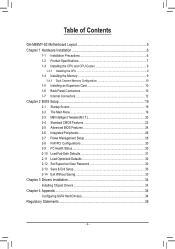
Table of Contents GA-M68MT-S2 Motherboard Layout 5 Chapter 1 Hardware Installation 6 1-1 Installation Precautions 6 1-2 Product Specifications 7 1-3 Installing the CPU and CPU Cooler 9 1-3-1 Installing the CPU...9 1-4 Installing the Memory 9 1-4-1 Dual Channel Memory Configuration 10 1-5 ...
Table of Contents GA-M68MT-S2 Motherboard Layout 5 Chapter 1 Hardware Installation 6 1-1 Installation Precautions 6 1-2 Product Specifications 7 1-3 Installing the CPU and CPU Cooler 9 1-3-1 Installing the CPU...9 1-4 Installing the Memory 9 1-4-1 Dual Channel Memory Configuration 10 1-5 ...
Manual
Page 5
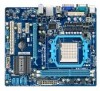
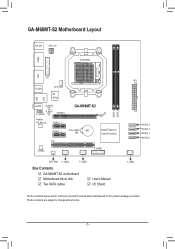
... COMA VGA LPT R_USB CPU_FAN iTE IT8720 LAN USB AUDIO M_BIOS B_BIOS F_AUDIO PCIEX16 Realtek RTL8211CL PCIEX1_1 GA-M68MT-S2 PCIEX1_2 CLR_CMOS BAT NVIDIA® GeForce 7025/nForce 630a PCI CODEC F_PANEL SYS_FAN F_USB3 F_USB2 Box Contents GA-M68MT-S2 motherboard Motherboard driver disk Two SATA cables User's Manual I/O Shield DDR3_1 DDR3_2 ATX SATA2_3 SATA2_2 SATA2_1 SATA2_0 F_USB1...
... COMA VGA LPT R_USB CPU_FAN iTE IT8720 LAN USB AUDIO M_BIOS B_BIOS F_AUDIO PCIEX16 Realtek RTL8211CL PCIEX1_1 GA-M68MT-S2 PCIEX1_2 CLR_CMOS BAT NVIDIA® GeForce 7025/nForce 630a PCI CODEC F_PANEL SYS_FAN F_USB3 F_USB2 Box Contents GA-M68MT-S2 motherboard Motherboard driver disk Two SATA cables User's Manual I/O Shield DDR3_1 DDR3_2 ATX SATA2_3 SATA2_2 SATA2_1 SATA2_0 F_USB1...
Manual
Page 6
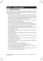
... system on an uneven surface. • Do not place the computer system in a high-temperature environment. • Turning on the motherboard, make sure the power supply voltage has been set according to the local voltage standard. • Before using the product, please verify...It is best to wear an electrostatic discharge (ESD) wrist strap when handling electronic com- Chapter 1 Hardware Installation 1-1 Installation Precautions The motherboard contains numerous delicate electronic circuits and components which can lead to damage to system components as well as physical harm to the user. ...
... system on an uneven surface. • Do not place the computer system in a high-temperature environment. • Turning on the motherboard, make sure the power supply voltage has been set according to the local voltage standard. • Before using the product, please verify...It is best to wear an electrostatic discharge (ESD) wrist strap when handling electronic com- Chapter 1 Hardware Installation 1-1 Installation Precautions The motherboard contains numerous delicate electronic circuits and components which can lead to damage to system components as well as physical harm to the user. ...
Manual
Page 8
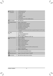
... for Auto Green Support for ON/OFF Charge Norton Internet Security (OEM version) Operating System w Support for EasyTune * Available functions in EasyTune may differ by motherboard model.
... for Auto Green Support for ON/OFF Charge Norton Internet Security (OEM version) Operating System w Support for EasyTune * Available functions in EasyTune may differ by motherboard model.
Manual
Page 9
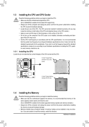
...triangle) of the CPU socket and the CPU. It is not installed, otherwise overheating and dam- A memory module can be used. (Go to GIGABYTE's website for the latest supported memory speeds and memory modules.) • Always turn off the computer and unplug the power cord from the power ...Installing the CPU and CPU Cooler Read the following guidelines before you begin to install the CPU: • Make sure that the motherboard supports the CPU. (Go to GIGABYTE's website for the latest CPU support list.) • Always turn off the computer and unplug the power cord from the power ...
...triangle) of the CPU socket and the CPU. It is not installed, otherwise overheating and dam- A memory module can be used. (Go to GIGABYTE's website for the latest supported memory speeds and memory modules.) • Always turn off the computer and unplug the power cord from the power ...Installing the CPU and CPU Cooler Read the following guidelines before you begin to install the CPU: • Make sure that the motherboard supports the CPU. (Go to GIGABYTE's website for the latest CPU support list.) • Always turn off the computer and unplug the power cord from the power ...
Manual
Page 10
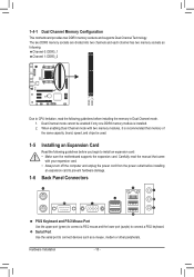
.../2 Mouse Port Use the upper port (green) to connect a PS/2 mouse and the lower port (purple) to install an expansion card: • Make sure the motherboard supports the expansion card. Serial Port Use the serial port to connect devices such as following: Channel 0: DDR3_1 Channel 1: DDR3_2 DDR3_1 DDR3_2 Due to CPU... turn off the computer and unplug the power cord from the power outlet before you begin to connect a PS/2 keyboard. 1-4-1 Dual Channel Memory Configuration This motherboard provides two DDR3 memory sockets and supports Dual Channel Technology.
.../2 Mouse Port Use the upper port (green) to connect a PS/2 mouse and the lower port (purple) to install an expansion card: • Make sure the motherboard supports the expansion card. Serial Port Use the serial port to connect devices such as following: Channel 0: DDR3_1 Channel 1: DDR3_2 DDR3_1 DDR3_2 Due to CPU... turn off the computer and unplug the power cord from the power outlet before you begin to connect a PS/2 keyboard. 1-4-1 Dual Channel Memory Configuration This motherboard provides two DDR3 memory sockets and supports Dual Channel Technology.
Manual
Page 11
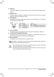
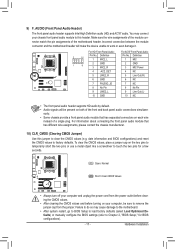
Line Out Jack (Front Speaker Out, Green) The default line out jack. Do not rock it straight out from the motherboard. • When removing the cable, pull it side to side to 1 Gbps data rate. RJ-45 LAN Port The Gigabit Ethernet LAN port provides Internet ...
Line Out Jack (Front Speaker Out, Green) The default line out jack. Do not rock it straight out from the motherboard. • When removing the cable, pull it side to side to 1 Gbps data rate. RJ-45 LAN Port The Gigabit Ethernet LAN port provides Internet ...
Manual
Page 12
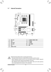
... connectors you wish to connect. • Before installing the devices, be sure to the devices. • After installing the device and before turning on the motherboard.
... connectors you wish to connect. • Before installing the devices, be sure to the devices. • After installing the device and before turning on the motherboard.
Manual
Page 13
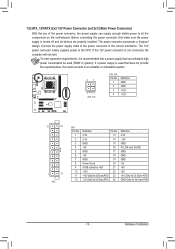
... connector in the correct orientation. The power connector possesses a foolproof design. To meet expansion requirements, it is turned off and all the components on the motherboard. If the 12V power connector is used that can withstand high power consumption be used (500W or greater). Before connecting the power connector, first make...
... connector in the correct orientation. The power connector possesses a foolproof design. To meet expansion requirements, it is turned off and all the components on the motherboard. If the 12V power connector is used that can withstand high power consumption be used (500W or greater). Before connecting the power connector, first make...
Manual
Page 14
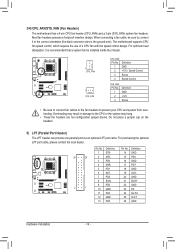
... 12 GND 25 SLCT 13 PD5 26 GND Hardware Installation - 14 - DEBUG PORT 3/4) CPU_FAN/SYS_FAN (Fan Headers) The motherboard has a 4-pin CPU fan header (CPU_FAN) and a 3-pin (SYS_FAN) system fan headers. The motherboard supports CPU fan speed control, which requires the use of a CPU fan with fan speed control design. Do not...
... 12 GND 25 SLCT 13 PD5 26 GND Hardware Installation - 14 - DEBUG PORT 3/4) CPU_FAN/SYS_FAN (Fan Headers) The motherboard has a 4-pin CPU fan header (CPU_FAN) and a 3-pin (SYS_FAN) system fan headers. The motherboard supports CPU fan speed control, which requires the use of a CPU fan with fan speed control design. Do not...
Manual
Page 17
...- 17 - To clear the CMOS values, place a jumper cap on each wire instead of a single plug. You may cause damage to the motherboard. • After system restart, go to BIOS Setup to load factory defaults (select Load Optimized Defaults) or manually configure the BIOS settings (refer ...to this jumper to factory defaults. Incorrect connection between the module connector and the motherboard header will be sure to remove the jumper cap from the power outlet before clearing the CMOS values. • After clearing the CMOS...
...- 17 - To clear the CMOS values, place a jumper cap on each wire instead of a single plug. You may cause damage to the motherboard. • After system restart, go to BIOS Setup to load factory defaults (select Load Optimized Defaults) or manually configure the BIOS settings (refer ...to this jumper to factory defaults. Incorrect connection between the module connector and the motherboard header will be sure to remove the jumper cap from the power outlet before clearing the CMOS values. • After clearing the CMOS...
Manual
Page 19
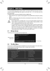
...8226; Because BIOS flashing is potentially risky, if you do it is turned on the screen. BIOS Setup M68MT-S2 D9 . . . : BIOS Setup : XpressRecovery2 : Boot Menu : Qflash 10/18/2010-NV-MCP68-6A61KG0PC... not flash the BIOS. Use arrow keys to move among the items and press to boot. Motherboard Model BIOS Version Award Modular BIOS v6.00PG, An Energy Star Ally Copyright (C) 1984-2010,...to) to prevent system instability or other unexpected results. To upgrade the BIOS, use either the GIGABYTE Q-Flash or @BIOS utility. • Q-Flash allows the user to quickly and easily upgrade or...
...8226; Because BIOS flashing is potentially risky, if you do it is turned on the screen. BIOS Setup M68MT-S2 D9 . . . : BIOS Setup : XpressRecovery2 : Boot Menu : Qflash 10/18/2010-NV-MCP68-6A61KG0PC... not flash the BIOS. Use arrow keys to move among the items and press to boot. Motherboard Model BIOS Version Award Modular BIOS v6.00PG, An Energy Star Ally Copyright (C) 1984-2010,...to) to prevent system instability or other unexpected results. To upgrade the BIOS, use either the GIGABYTE Q-Flash or @BIOS utility. • Q-Flash allows the user to quickly and easily upgrade or...
Manual
Page 30
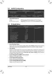
To clear the chassis intrusion status record, set Reset Case Open Status to Enabled, save the settings to the motherboard CI header. Current System/CPU Temperature Displays current system/CPU temperature. BIOS Setup - 30 - Current Voltage(V) Vcore/DDR3 1.5V/+3.3V/+12V Displays the current system ...
To clear the chassis intrusion status record, set Reset Case Open Status to Enabled, save the settings to the motherboard CI header. Current System/CPU Temperature Displays current system/CPU temperature. BIOS Setup - 30 - Current Voltage(V) Vcore/DDR3 1.5V/+3.3V/+12V Displays the current system ...
Manual
Page 31
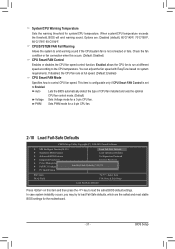
... fan installed and sets the optimal CPU fan control mode. (Default) Voltage Sets Voltage mode for system/CPU temperature. PWM Sets PWM mode for the motherboard. - 31 - BIOS Setup Options are the safest and most stable BIOS settings for a 4-pin CPU fan. 2-10 Load Fail-Safe Defaults CMOS Setup Utility-Copyright...
... fan installed and sets the optimal CPU fan control mode. (Default) Voltage Sets Voltage mode for system/CPU temperature. PWM Sets PWM mode for the motherboard. - 31 - BIOS Setup Options are the safest and most stable BIOS settings for a 4-pin CPU fan. 2-10 Load Fail-Safe Defaults CMOS Setup Utility-Copyright...
Manual
Page 34
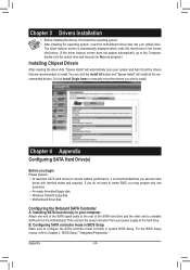
...end of the SATA signal cable to the rear of the SATA hard drive and the other end to available SATA port on the motherboard. Chapter 4 Appendix Configuring SATA Hard Drive(s) Before you wish to install. Installing SATA hard drive(s) in system BIOS Setup. Configuring ... scan your computer Attach one hard drive. • An empty formatted floppy disk. • Windows Vista/XP setup disk. • Motherboard driver disk. Chapter 3 Drivers Installation • Before installing the drivers, first install the operating system. • After installing the operating system, insert ...
...end of the SATA signal cable to the rear of the SATA hard drive and the other end to available SATA port on the motherboard. Chapter 4 Appendix Configuring SATA Hard Drive(s) Before you wish to install. Installing SATA hard drive(s) in system BIOS Setup. Configuring ... scan your computer Attach one hard drive. • An empty formatted floppy disk. • Windows Vista/XP setup disk. • Motherboard driver disk. Chapter 3 Drivers Installation • Before installing the drivers, first install the operating system. • After installing the operating system, insert ...
Manual
Page 35
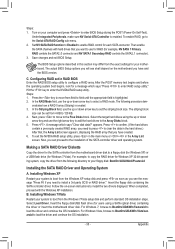
...depend on -screen instructions to configure a RAID array. Select the target hard drives using a SATA optical drive) containing the driver or insert the motherboard driver disk. Press to confirm. (If the hard drives contain a previously created RAID array, you want to use the up or down arrow ... (for a message which says "Clear disk data?" Under Integrated Peripherals, make sure NV Serial-ATA Controller is created. 3. Follow the on the motherboard you can be set in the hard drives.) After that, the Array List screen appears, displaying the RAID array that you need to select a...
...depend on -screen instructions to configure a RAID array. Select the target hard drives using a SATA optical drive) containing the driver or insert the motherboard driver disk. Press to confirm. (If the hard drives contain a previously created RAID array, you want to use the up or down arrow ... (for a message which says "Clear disk data?" Under Integrated Peripherals, make sure NV Serial-ATA Controller is created. 3. Follow the on the motherboard you can be set in the hard drives.) After that, the Array List screen appears, displaying the RAID array that you need to select a...
Manual
Page 36
...note that the information in this text. Under the Directive, used for details of Hazardous Substances (RoHS) Directive Statement GIGABYTE products have been carefully selected to high-efficiency performance, all respects at the time of properly. The parts and components ... Customer Care number listed in your electrical or electronic equipment is recycled in all GIGABYTE motherboards fulfill European Union regulations for activation of with your waste equipment at GIGABYTE are continuing our efforts to you can responsibly recycle or reuse most major worldwide safety...
...note that the information in this text. Under the Directive, used for details of Hazardous Substances (RoHS) Directive Statement GIGABYTE products have been carefully selected to high-efficiency performance, all respects at the time of properly. The parts and components ... Customer Care number listed in your electrical or electronic equipment is recycled in all GIGABYTE motherboards fulfill European Union regulations for activation of with your waste equipment at GIGABYTE are continuing our efforts to you can responsibly recycle or reuse most major worldwide safety...


