Manual
Page 1
GA-M68MT-D3P GA-M68MT-S2P AM3 socket motherboard for AMD Phenom™ II processor/ AMD Athlon™ II processor User's Manual Rev. 3001 12ME-M68MT2P-3001R
GA-M68MT-D3P GA-M68MT-S2P AM3 socket motherboard for AMD Phenom™ II processor/ AMD Athlon™ II processor User's Manual Rev. 3001 12ME-M68MT2P-3001R

Manual
Page 2
Motherboard GA-M68MT-D3P/GA-M68MT-S2P Dec. 31, 2010 Motherboard GA-M68MT-D3P GA-M68MT-S2P Dec. 31, 2010
Motherboard GA-M68MT-D3P/GA-M68MT-S2P Dec. 31, 2010 Motherboard GA-M68MT-D3P GA-M68MT-S2P Dec. 31, 2010

Manual
Page 3
... and features in this manual may be made by GIGABYTE without GIGABYTE's prior written permission. In order to their respective owners. For example, "REV: 1.0" means the revision of the motherboard is the property of this manual are legally registered to...User's Manual. For product-related information, check on our website at: http://www.gigabyte.com Identifying Your Motherboard Revision The revision number on your motherboard revision before updating motherboard BIOS, drivers, or when looking for technical information. The trademarks mentioned in this : "...
... and features in this manual may be made by GIGABYTE without GIGABYTE's prior written permission. In order to their respective owners. For example, "REV: 1.0" means the revision of the motherboard is the property of this manual are legally registered to...User's Manual. For product-related information, check on our website at: http://www.gigabyte.com Identifying Your Motherboard Revision The revision number on your motherboard revision before updating motherboard BIOS, drivers, or when looking for technical information. The trademarks mentioned in this : "...

Manual
Page 4
Table of Contents GA-M68MT-D3P/GA-M68MT-S2P Motherboard Layout 5 Chapter 1 Hardware Installation 6 1-1 Installation Precautions 6 1-2 Product Specifications 7 1-3 Installing the CPU and CPU Cooler 9 1-3-1 Installing the CPU...9 1-4 Installing the Memory 9 1-4-1 Dual Channel Memory Configuration 10 1-5 ...
Table of Contents GA-M68MT-D3P/GA-M68MT-S2P Motherboard Layout 5 Chapter 1 Hardware Installation 6 1-1 Installation Precautions 6 1-2 Product Specifications 7 1-3 Installing the CPU and CPU Cooler 9 1-3-1 Installing the CPU...9 1-4 Installing the Memory 9 1-4-1 Dual Channel Memory Configuration 10 1-5 ...

Manual
Page 5
... USB iTE IT8720 AUDIO F_AUDIO M_BIOS B_BIOS PCIEX16 Realtek RTL8211CL PCIEX1_1 GA-M68MT-D3P GA-M68MT-S2P PCIEX1_2 CLR_CMOS BAT PCI CODEC SYS_FAN F_USB3 F_USB2 ATX DDR3_1 DDR3_2 NVIDIA® GeForce 7025/nForce 630a F_PANEL F_USB1 SATA2_3 SATA2_2 SATA2_1 SATA2_0 Box Contents GA-M68MT-D3P or GA-M68MT-S2P motherboard Motherboard driver disk User's Manual I/O Shield Two SATA cables The box contents...
... USB iTE IT8720 AUDIO F_AUDIO M_BIOS B_BIOS PCIEX16 Realtek RTL8211CL PCIEX1_1 GA-M68MT-D3P GA-M68MT-S2P PCIEX1_2 CLR_CMOS BAT PCI CODEC SYS_FAN F_USB3 F_USB2 ATX DDR3_1 DDR3_2 NVIDIA® GeForce 7025/nForce 630a F_PANEL F_USB1 SATA2_3 SATA2_2 SATA2_1 SATA2_0 Box Contents GA-M68MT-D3P or GA-M68MT-S2P motherboard Motherboard driver disk User's Manual I/O Shield Two SATA cables The box contents...

Manual
Page 6
...required for warranty validation. • Always remove the AC power by your hardware components are connected. • To prevent damage to the motherboard, do not have an ESD wrist strap, keep your hands dry and first touch a metal object to eliminate static electricity. •...become damaged as a result of the product, please consult a certified computer technician. Chapter 1 Hardware Installation 1-1 Installation Precautions The motherboard contains numerous delicate electronic circuits and components which can lead to damage to system components as well as physical harm to the user....
...required for warranty validation. • Always remove the AC power by your hardware components are connected. • To prevent damage to the motherboard, do not have an ESD wrist strap, keep your hands dry and first touch a metal object to eliminate static electricity. •...become damaged as a result of the product, please consult a certified computer technician. Chapter 1 Hardware Installation 1-1 Installation Precautions The motherboard contains numerous delicate electronic circuits and components which can lead to damage to system components as well as physical harm to the user....

Manual
Page 8
... for Auto Green Support for ON/OFF Charge Norton Internet Security (OEM version) Operating System w Support for EasyTune * Available functions in EasyTune may differ by motherboard model.
... for Auto Green Support for ON/OFF Charge Norton Internet Security (OEM version) Operating System w Support for EasyTune * Available functions in EasyTune may differ by motherboard model.

Manual
Page 9
...Pin One AM3 CPU 1-4 Installing the Memory Read the following guidelines before you begin to install the memory: • Make sure that the motherboard supports the memory. It is not installed, otherwise overheating and dam- Hardware Installation 1-3 Installing the CPU and CPU Cooler Read the following ...guidelines before you begin to install the CPU: • Make sure that the motherboard supports the CPU. (Go to GIGABYTE's website for the latest CPU support list.) • Always turn off the computer and unplug the power cord from the ...
...Pin One AM3 CPU 1-4 Installing the Memory Read the following guidelines before you begin to install the memory: • Make sure that the motherboard supports the memory. It is not installed, otherwise overheating and dam- Hardware Installation 1-3 Installing the CPU and CPU Cooler Read the following ...guidelines before you begin to install the CPU: • Make sure that the motherboard supports the CPU. (Go to GIGABYTE's website for the latest CPU support list.) • Always turn off the computer and unplug the power cord from the ...

Manual
Page 10
..., modem or other peripherals. Hardware Installation - 10 - Carefully read the following guidelines before installing the memory in Dual Channel mode. 1. 1-4-1 Dual Channel Memory Configuration This motherboard provides two DDR3 memory sockets and supports Dual Channel Technology. When enabling Dual Channel mode with your expansion card. • Always turn off the computer.../2 Mouse Port Use the upper port (green) to connect a PS/2 mouse and the lower port (purple) to install an expansion card: • Make sure the motherboard supports the expansion card.
..., modem or other peripherals. Hardware Installation - 10 - Carefully read the following guidelines before installing the memory in Dual Channel mode. 1. 1-4-1 Dual Channel Memory Configuration This motherboard provides two DDR3 memory sockets and supports Dual Channel Technology. When enabling Dual Channel mode with your expansion card. • Always turn off the computer.../2 Mouse Port Use the upper port (green) to connect a PS/2 mouse and the lower port (purple) to install an expansion card: • Make sure the motherboard supports the expansion card.

Manual
Page 11
... 2.0/1.1 specification. Do not rock it side to side to a back panel connector, first remove the cable from your device and then remove it from the motherboard. • When removing the cable, pull it straight out from the connector. Use this audio jack for line in a 4/5.1-channel audio configuration. Mic In Jack...
... 2.0/1.1 specification. Do not rock it side to side to a back panel connector, first remove the cable from your device and then remove it from the motherboard. • When removing the cable, pull it straight out from the connector. Use this audio jack for line in a 4/5.1-channel audio configuration. Mic In Jack...

Manual
Page 12
..., make sure your devices are compliant with the connectors you wish to connect. • Before installing the devices, be sure to the connector on the motherboard. Unplug the power cord from the power outlet to prevent damage to the devices. • After installing the device and before connecting external devices: •...
..., make sure your devices are compliant with the connectors you wish to connect. • Before installing the devices, be sure to the connector on the motherboard. Unplug the power cord from the power outlet to prevent damage to the devices. • After installing the device and before connecting external devices: •...

Manual
Page 13
... (500W or greater). Connect the power supply cable to the CPU. If the 12V power connector is turned off and all the components on the motherboard. Hardware Installation Before connecting the power connector, first make sure the power supply is not connected, the computer will not start. The power connector possesses...
... (500W or greater). Connect the power supply cable to the CPU. If the 12V power connector is turned off and all the components on the motherboard. Hardware Installation Before connecting the power connector, first make sure the power supply is not connected, the computer will not start. The power connector possesses...

Manual
Page 14
... cap on the headers. 5) LPT (Parallel Port Header) The LPT header can provide one parallel port via an optional LPT port cable. Pin No. The motherboard supports CPU fan speed control, which requires the use of a CPU fan with fan speed control design. For purchasing the optional LPT port cable, please...; Be sure to connect fan cables to the fan headers to prevent your CPU and system from overheating. DEBUG PORT 3/4) CPU_FAN/SYS_FAN (Fan Headers) The motherboard has a 4-pin CPU fan header (CPU_FAN) and a 3-pin (SYS_FAN) system fan headers.
... cap on the headers. 5) LPT (Parallel Port Header) The LPT header can provide one parallel port via an optional LPT port cable. Pin No. The motherboard supports CPU fan speed control, which requires the use of a CPU fan with fan speed control design. For purchasing the optional LPT port cable, please...; Be sure to connect fan cables to the fan headers to prevent your CPU and system from overheating. DEBUG PORT 3/4) CPU_FAN/SYS_FAN (Fan Headers) The motherboard has a 4-pin CPU fan header (CPU_FAN) and a 3-pin (SYS_FAN) system fan headers.

Manual
Page 17
...The front panel audio header supports Intel High Definition audio (HD) and AC'97 audio. Incorrect connection between the module connector and the motherboard header will be sure to clear the CMOS values (e.g. Open: Normal Short: Clear CMOS Values • Always turn off your chassis front...module to factory defaults. Hardware Installation For information about connecting the front panel audio module that has separated connectors on both of the motherboard header. Failure to do so may connect your computer and unplug the power cord from the jumper. For HD Front Panel Audio...
...The front panel audio header supports Intel High Definition audio (HD) and AC'97 audio. Incorrect connection between the module connector and the motherboard header will be sure to clear the CMOS values (e.g. Open: Normal Short: Clear CMOS Values • Always turn off your chassis front...module to factory defaults. Hardware Installation For information about connecting the front panel audio module that has separated connectors on both of the motherboard header. Failure to do so may connect your computer and unplug the power cord from the jumper. For HD Front Panel Audio...
Manual
Page 19
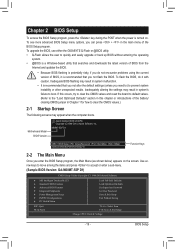
...GIGABYTE Q-Flash or @BIOS utility. • Q-Flash allows the user to quickly and easily upgrade or back up BIOS without entering the operating system. • @BIOS is a Windows-based utility that searches and downloads the latest version of BIOS, it with caution. M68MT...on . Inadequately altering the settings may appear when the computer boots. Motherboard Model BIOS Version Award Modular BIOS v6.00PG Copyright (C) 1984-2010, ... 1 for how to accept or enter a sub-menu. (Sample BIOS Version: GA-M68MT-S2P D1) CMOS Setup Utility-Copyright (C) 1984-2010 Award Software MB ...
...GIGABYTE Q-Flash or @BIOS utility. • Q-Flash allows the user to quickly and easily upgrade or back up BIOS without entering the operating system. • @BIOS is a Windows-based utility that searches and downloads the latest version of BIOS, it with caution. M68MT...on . Inadequately altering the settings may appear when the computer boots. Motherboard Model BIOS Version Award Modular BIOS v6.00PG Copyright (C) 1984-2010, ... 1 for how to accept or enter a sub-menu. (Sample BIOS Version: GA-M68MT-S2P D1) CMOS Setup Utility-Copyright (C) 1984-2010 Award Software MB ...

Manual
Page 30
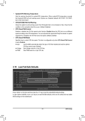
... Opened field will show "No" at next boot. (Default: Disabled) Case Opened Displays the detection status of the chassis intrusion detection device attached to the motherboard CI header. Enabled clears the record of previous chassis intrusion status. BIOS Setup - 30 - Current Voltage(V) Vcore/DDR3 1.5V/+3.3V/+12V Displays the current system...
... Opened field will show "No" at next boot. (Default: Disabled) Case Opened Displays the detection status of the chassis intrusion detection device attached to the motherboard CI header. Enabled clears the record of previous chassis intrusion status. BIOS Setup - 30 - Current Voltage(V) Vcore/DDR3 1.5V/+3.3V/+12V Displays the current system...
Manual
Page 31
.../158oF, 80oC/176oF, 90oC/194oF. In case system instability occurs, you may try to the CPU temperature. BIOS Setup PWM Sets PWM mode for the motherboard. - 31 -
.../158oF, 80oC/176oF, 90oC/194oF. In case system instability occurs, you may try to the CPU temperature. BIOS Setup PWM Sets PWM mode for the motherboard. - 31 -
Manual
Page 34
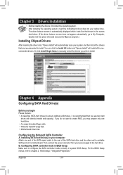
...scan your computer Attach one hard drive. • An empty formatted floppy disk. • Windows Vista/XP setup disk. • Motherboard driver disk. Or click Install Single Items to manually select the drivers you use two hard drives with identical model and capacity). If ... Chapter 3 Drivers Installation • Before installing the drivers, first install the operating system. • After installing the operating system, insert the motherboard driver disk into your power supply to the hard drive. Configuring SATA controller mode in BIOS Setup Make sure to Chapter 2, "BIOS Setup," ...
...scan your computer Attach one hard drive. • An empty formatted floppy disk. • Windows Vista/XP setup disk. • Motherboard driver disk. Or click Install Single Items to manually select the drivers you use two hard drives with identical model and capacity). If ... Chapter 3 Drivers Installation • Before installing the drivers, first install the operating system. • After installing the operating system, insert the motherboard driver disk into your power supply to the hard drive. Configuring SATA controller mode in BIOS Setup Make sure to Chapter 2, "BIOS Setup," ...

Manual
Page 35
...7/Vista). Follow the on-screen instructions to a floppy disk (for Windows XP) or a USB flash drive (for the SATA controller from the motherboard driver disk to install the two drivers displayed. B. For Windows 7, browse to BootDrv\UDA\Win7\sataraid to enter BIOS Setup during the POST (...down arrow key to the Array Disks block. 5. Select the target hard drives using a SATA optical drive) containing the driver or insert the motherboard driver disk. Configuring RAID set the striping block size. C. After the POST memory test begins and before the operating system boot begins, look...
...7/Vista). Follow the on-screen instructions to a floppy disk (for Windows XP) or a USB flash drive (for the SATA controller from the motherboard driver disk to install the two drivers displayed. B. For Windows 7, browse to BootDrv\UDA\Win7\sataraid to enter BIOS Setup during the POST (...down arrow key to the Array Disks block. 5. Select the target hard drives using a SATA optical drive) containing the driver or insert the motherboard driver disk. Configuring RAID set the striping block size. C. After the POST memory test begins and before the operating system boot begins, look...


