Manual
Page 4
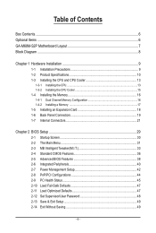
Table of Contents Box Contents...6 Optional Items...6 GA-M68M-S2P Motherboard Layout 7 Block Diagram...8 Chapter 1 Hardware Installation 9 1-1 Installation Precautions 9 1-2 Product Specifications 10 1-3 Installing the CPU and CPU Cooler 13...Dual Channel Memory Configuration 16 1-4-2 Installing a Memory 17 1-5 Installing an Expansion Card 18 1-6 Back Panel Connectors 19 1-7 Internal Connectors 21 Chapter 2 BIOS Setup 29 2-1 Startup Screen 30 2-2 The Main Menu 31 2-3 MB Intelligent Tweaker(M.I.T 33 2-4 Standard CMOS Features 36 2-5 Advanced BIOS Features 38 2-6 Integrated ...
Table of Contents Box Contents...6 Optional Items...6 GA-M68M-S2P Motherboard Layout 7 Block Diagram...8 Chapter 1 Hardware Installation 9 1-1 Installation Precautions 9 1-2 Product Specifications 10 1-3 Installing the CPU and CPU Cooler 13...Dual Channel Memory Configuration 16 1-4-2 Installing a Memory 17 1-5 Installing an Expansion Card 18 1-6 Back Panel Connectors 19 1-7 Internal Connectors 21 Chapter 2 BIOS Setup 29 2-1 Startup Screen 30 2-2 The Main Menu 31 2-3 MB Intelligent Tweaker(M.I.T 33 2-4 Standard CMOS Features 36 2-5 Advanced BIOS Features 38 2-6 Integrated ...
Manual
Page 18
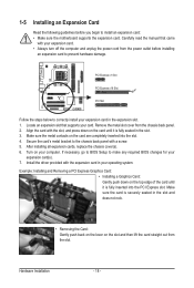
... Graphics Card: • Installing a Graphics Card: Gently push down on the card are completely inserted into the PCI Express slot. If necessary, go to BIOS Setup to make any required BIOS changes for your expansion card. • Always turn off the computer and unplug the power cord from the chassis back...
... Graphics Card: • Installing a Graphics Card: Gently push down on the card are completely inserted into the PCI Express slot. If necessary, go to BIOS Setup to make any required BIOS changes for your expansion card. • Always turn off the computer and unplug the power cord from the chassis back...
Manual
Page 25
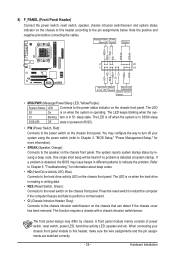
... system is operating. The LED S0 On is detected at system startup. When connecting your system using the power switch (refer to Chapter 2, "BIOS Setup," "Power Management Setup," for information about beep codes. • HD (Hard Drive Activity LED, Blue) Connects to the power status indicator on the chassis front panel. Note...
... system is operating. The LED S0 On is detected at system startup. When connecting your system using the power switch (refer to Chapter 2, "BIOS Setup," "Power Management Setup," for information about beep codes. • HD (Hard Drive Activity LED, Blue) Connects to the power status indicator on the chassis front panel. Note...
Manual
Page 28
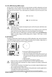
..., or the CMOS values may not be accurate or may be lost. date information and BIOS configurations) and reset the CMOS values to Chapter 2, "BIOS Setup," for 5 seconds.) 3. Failure to do so may cause damage to the motherboard. • After system restart, go to BIOS...
..., or the CMOS values may not be accurate or may be lost. date information and BIOS configurations) and reset the CMOS values to Chapter 2, "BIOS Setup," for 5 seconds.) 3. Failure to do so may cause damage to the motherboard. • After system restart, go to BIOS...
Manual
Page 29
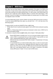
...updates the BIOS. Its major functions include conducting the Power-On Self-Test (POST) during the POST. To upgrade the BIOS, use either the GIGABYTE Q-Flash or @BIOS utility. • Q-Flash allows the user to clear the CMOS values.) - 29 - For instructions on the motherboard. ...system malfunction. • BIOS will emit a beep code during system startup, saving system parameters and loading operating system, etc. Chapter 2 BIOS Setup BIOS (Basic Input and Output System) records hardware parameters of the system in the CMOS on using the current version of BIOS, it with ...
...updates the BIOS. Its major functions include conducting the Power-On Self-Test (POST) during the POST. To upgrade the BIOS, use either the GIGABYTE Q-Flash or @BIOS utility. • Q-Flash allows the user to clear the CMOS values.) - 29 - For instructions on the motherboard. ...system malfunction. • BIOS will emit a beep code during system startup, saving system parameters and loading operating system, etc. Chapter 2 BIOS Setup BIOS (Basic Input and Output System) records hardware parameters of the system in the CMOS on using the current version of BIOS, it with ...
Manual
Page 30
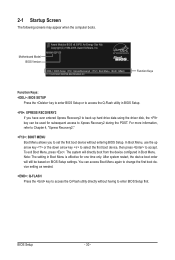
... to Xpress Recovery2 during the POST. BIOS Setup - 30 - Note: The setting in Boot Menu is effective for subsequent access to accept. 2-1 Startup Screen The following screens may appear when the computer boots. M68M-S2P D5 . . . . : BIOS Setup : XpressRecovery2 : Boot Menu : Qflash 11.../13/2009-NF-MCP68-6A61KG0GC-00 Function Keys Function Keys: : BIOS SETUP Press the key to enter BIOS Setup or to access the Q-Flash utility in Boot Menu...
... to Xpress Recovery2 during the POST. BIOS Setup - 30 - Note: The setting in Boot Menu is effective for subsequent access to accept. 2-1 Startup Screen The following screens may appear when the computer boots. M68M-S2P D5 . . . . : BIOS Setup : XpressRecovery2 : Boot Menu : Qflash 11.../13/2009-NF-MCP68-6A61KG0GC-00 Function Keys Function Keys: : BIOS SETUP Press the key to enter BIOS Setup or to access the Q-Flash utility in Boot Menu...

Manual
Page 31
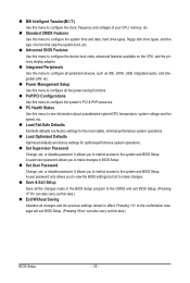
...61565; MB Intelligent Tweaker(M.I.T.) Standard CMOS Features Advanced BIOS Features Integrated Peripherals Power Management Setup PnP/PCI Configurations PC Health Status ESC: Quit F8: Q-Flash Load Fail-Safe Defaults Load Optimized Defaults Set... Supervisor Password Set User Password Save & Exit Setup Exit Without Saving Select Item F10: Save & Exit Setup Change CPU's Clock & Voltage BIOS Setup Program Function Keys Move the selection bar to select an item Execute command or...
...61565; MB Intelligent Tweaker(M.I.T.) Standard CMOS Features Advanced BIOS Features Integrated Peripherals Power Management Setup PnP/PCI Configurations PC Health Status ESC: Quit F8: Q-Flash Load Fail-Safe Defaults Load Optimized Defaults Set... Supervisor Password Set User Password Save & Exit Setup Exit Without Saving Select Item F10: Save & Exit Setup Change CPU's Clock & Voltage BIOS Setup Program Function Keys Move the selection bar to select an item Execute command or...
Manual
Page 32
... can also carry out this task.) Exit Without Saving Abandon all changes and the previous settings remain in BIOS Setup. Set User Password Change, set , or disable password. A user password only allows you to restrict access to see information about ... Peripherals Use this menu to configure all peripheral devices, such as IDE, SATA, USB, integrated audio, and integrated LAN, etc. Power Management Setup Use this menu to configure all the power-saving functions. PnP/PCI Configurations Use this menu to configure the system's PCI & PnP resources. ...
... can also carry out this task.) Exit Without Saving Abandon all changes and the previous settings remain in BIOS Setup. Set User Password Change, set , or disable password. A user password only allows you to restrict access to see information about ... Peripherals Use this menu to configure all peripheral devices, such as IDE, SATA, USB, integrated audio, and integrated LAN, etc. Power Management Setup Use this menu to configure all the power-saving functions. PnP/PCI Configurations Use this menu to configure the system's PCI & PnP resources. ...

Manual
Page 33
....66. X2.66 Sets Memory Clock to DDR 800. - 33 - When you made is set the memory clock as required. BIOS Setup Incorrectly doing overclock may result in damage to CPU, chipset, or memory and reduce the useful life of these components. Auto lets BIOS... the memory clock. DDR 667 Sets Memory Clock to DDR 533. DDR 533 Sets Memory Clock to DDR 667. 2-3 MB Intelligent Tweaker(M.I.T.) CMOS Setup Utility-Copyright (C) 1984-2009 Award Software MB Intelligent Tweaker(M.I.T.) Set Memory Clock x Memory Clock } DRAM Configuration [Auto] x3.33 667Mhz [Press ...
....66. X2.66 Sets Memory Clock to DDR 800. - 33 - When you made is set the memory clock as required. BIOS Setup Incorrectly doing overclock may result in damage to CPU, chipset, or memory and reduce the useful life of these components. Auto lets BIOS... the memory clock. DDR 667 Sets Memory Clock to DDR 533. DDR 533 Sets Memory Clock to DDR 667. 2-3 MB Intelligent Tweaker(M.I.T.) CMOS Setup Utility-Copyright (C) 1984-2009 Award Software MB Intelligent Tweaker(M.I.T.) Set Memory Clock x Memory Clock } DRAM Configuration [Auto] x3.33 667Mhz [Press ...
Manual
Page 34
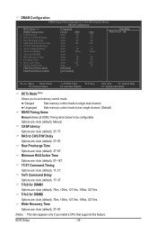
Minimum RAS Active Time Options are: Auto (default), 5T~18T. 1T/2T Command Timing Options are : Auto (default), 3T~6T. DRAM Configuration CMOS Setup Utility-Copyright (C) 1984-2009 Award Software DRAM Configuration DCTs Mode (Note) DDRII Timing Items x CAS# latency x RAS to CAS R/W Delay x Row Precharge Time x Minimum RAS ... below to RAS Delay CKE Power Down Mode CKE Power Down Control [Unganged] [Auto] SPD Auto 5T Auto 5T Auto 5T Auto 15T Auto -- BIOS Setup - 34 -
Minimum RAS Active Time Options are: Auto (default), 5T~18T. 1T/2T Command Timing Options are : Auto (default), 3T~6T. DRAM Configuration CMOS Setup Utility-Copyright (C) 1984-2009 Award Software DRAM Configuration DCTs Mode (Note) DDRII Timing Items x CAS# latency x RAS to CAS R/W Delay x Row Precharge Time x Minimum RAS ... below to RAS Delay CKE Power Down Mode CKE Power Down Control [Unganged] [Auto] SPD Auto 5T Auto 5T Auto 5T Auto 15T Auto -- BIOS Setup - 34 -

Manual
Page 35
Options are : Auto (default), 2T, 3T. CKE Power Down Mode Determines whether to set the memory to power down mode when the CKE pin is closed. (Default: Disabled) CKE Power Down Control Allows you to RAS Delay Options are : Auto (default), 11T~26T. Precharge Time Options are per Channel (Default), per CS. - 35 - RAS to select a CKE power down mode. BIOS Setup Row Cycle Time Options are : Auto (default), 2T~5T.
Options are : Auto (default), 2T, 3T. CKE Power Down Mode Determines whether to set the memory to power down mode when the CKE pin is closed. (Default: Disabled) CKE Power Down Control Allows you to RAS Delay Options are : Auto (default), 11T~26T. Precharge Time Options are per Channel (Default), per CS. - 35 - RAS to select a CKE power down mode. BIOS Setup Row Cycle Time Options are : Auto (default), 2T~5T.

Manual
Page 36
IDE Channel 0 Master/Slave IDE HDD Auto-Detection Press to autodetect the parameters of the IDE/SATA device on this channel. BIOS Setup - 36 - is week (read-only), month, date and year. IDE Channel 2, 3, 4, 5 Master IDE Auto-Detection Press to autodetect the parameters ...methods below : • Auto Lets the BIOS automatically detect IDE/SATA devices during the POST for faster system startup. 2-4 Standard CMOS Features CMOS Setup Utility-Copyright (C) 1984-2009 Award Software Standard CMOS Features Date (mm:dd:yy) Time (hh:mm:ss) Fri, Aug 28 2009 22:31...
IDE Channel 0 Master/Slave IDE HDD Auto-Detection Press to autodetect the parameters of the IDE/SATA device on this channel. BIOS Setup - 36 - is week (read-only), month, date and year. IDE Channel 2, 3, 4, 5 Master IDE Auto-Detection Press to autodetect the parameters ...methods below : • Auto Lets the BIOS automatically detect IDE/SATA devices during the POST for faster system startup. 2-4 Standard CMOS Features CMOS Setup Utility-Copyright (C) 1984-2009 Award Software Standard CMOS Features Date (mm:dd:yy) Time (hh:mm:ss) Fri, Aug 28 2009 22:31...
Manual
Page 37
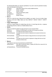
... operating system. Capacity Approximate capacity of extended memory. - 37 - Landing Zone Landing zone. Floppy 3 Mode Support Allows you to select the type of heads. BIOS Setup Extended Memory The amount of the currently installed hard drive. Head Number of floppy disk drive installed in your hard drive specifications. Memory These fields...
... operating system. Capacity Approximate capacity of extended memory. - 37 - Landing Zone Landing zone. Floppy 3 Mode Support Allows you to select the type of heads. BIOS Setup Extended Memory The amount of the currently installed hard drive. Head Number of floppy disk drive installed in your hard drive specifications. Memory These fields...
Manual
Page 38
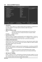
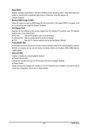
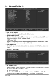
...Mode Backup BIOS Image to HDD Init Display First Frame Buffer Size Onboard GPU [Enabled] [Auto] [Press Enter] [Floppy] [Hard Disk] [CDROM] [Setup] [Disabled] [Disabled] [Disabled] [PEG] [64M] [Enable If No Ext PEG] Item Help Menu Level Move Enter: Select F5: Previous ...Optimized Defaults Virtualization Virtualization allows a platform to issue warnings when a third party hardware monitor utility is installed. (Default: Enabled) BIOS Setup - 38 - Hard Disk Boot Priority Specifies the sequence of your system to report read/write errors of the hard drive and to...
...Mode Backup BIOS Image to HDD Init Display First Frame Buffer Size Onboard GPU [Enabled] [Auto] [Press Enter] [Floppy] [Hard Disk] [CDROM] [Setup] [Disabled] [Disabled] [Disabled] [PEG] [64M] [Enable If No Ext PEG] Item Help Menu Level Move Enter: Select F5: Previous ...Optimized Defaults Virtualization Virtualization allows a platform to issue warnings when a third party hardware monitor utility is installed. (Default: Enabled) BIOS Setup - 38 - Hard Disk Boot Priority Specifies the sequence of your system to report read/write errors of the hard drive and to...
Manual
Page 39
... corrupted, it will use only this image file. (Default: Disabled) Init Display First Specifies the first initiation of system memory allocated solely for display. BIOS Setup If you wish to set up a dual view configuration, set this item to the hard drive. Options are: Disabled, 32MB, 64MB (Default), 128MB, 256MB. PCI...
... corrupted, it will use only this image file. (Default: Disabled) Init Display First Specifies the first initiation of system memory allocated solely for display. BIOS Setup If you wish to set up a dual view configuration, set this item to the hard drive. Options are: Disabled, 32MB, 64MB (Default), 128MB, 256MB. PCI...
Manual
Page 40
...Enables or disables prefetch mode for the first channel of memory allocated for the integrated SATA 3Gb/s controllers. Serial-ATA RAID Config CMOS Setup Utility-Copyright (C) 1984-2009 Award Software Serial-ATA RAID Config NV SATA RAID function x NV SATA 1 Primary RAID x NV ... or disables RAID for USB devices. Enabled activates the IDE prefetch buffer to Enabled. (Default: Enabled) BIOS Setup - 40 - 2-6 Integrated Peripherals CMOS Setup Utility-Copyright (C) 1984-2009 Award Software Integrated Peripherals On-Chip IDE Channel NV Serial-ATA Controller IDE Prefetch Mode...
...Enables or disables prefetch mode for the first channel of memory allocated for the integrated SATA 3Gb/s controllers. Serial-ATA RAID Config CMOS Setup Utility-Copyright (C) 1984-2009 Award Software Serial-ATA RAID Config NV SATA RAID function x NV SATA 1 Primary RAID x NV ... or disables RAID for USB devices. Enabled activates the IDE prefetch buffer to Enabled. (Default: Enabled) BIOS Setup - 40 - 2-6 Integrated Peripherals CMOS Setup Utility-Copyright (C) 1984-2009 Award Software Integrated Peripherals On-Chip IDE Channel NV Serial-ATA Controller IDE Prefetch Mode...
Manual
Page 41
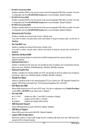
... Mode Selects an operating mode for the onboard parallel (LPT) port. Options are : Auto, 2F8/IRQ3, 3F8/IRQ4(default), 3E8/IRQ4, 2E8/IRQ3, Disabled. BIOS Setup Options are : 3 (default), 1. Options are : SPP (Standard Parallel Port) (default), EPP (Enhanced Parallel Port), ECP (Extended Capabilities Port), ECP+EPP. ECP Mode Use DMA Selects...
... Mode Selects an operating mode for the onboard parallel (LPT) port. Options are : Auto, 2F8/IRQ3, 3F8/IRQ4(default), 3E8/IRQ4, 2E8/IRQ3, Disabled. BIOS Setup Options are : 3 (default), 1. Options are : SPP (Standard Parallel Port) (default), EPP (Enhanced Parallel Port), ECP (Extended Capabilities Port), ECP+EPP. ECP Mode Use DMA Selects...
Manual
Page 42
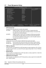
... system appears to turn off instantly. (Default) Delay 4 Sec. Press and hold the power button for less than in a low power mode. BIOS Setup - 42 - S3(STR) Enables the system to enter the ACPI S3 (Suspend to enter the ACPI S1 (Power on Suspend) sleep state. Instant-Off.... Note: To use this function, you need an ATX power supply providing at any time. 2-7 Power Management Setup CMOS Setup Utility-Copyright (C) 1984-2009 Award Software Power Management Setup ACPI Suspend Type Soft-Off by Power button PME Event Wake Up Modem Ring On USB Resume from the installed ...
... system appears to turn off instantly. (Default) Delay 4 Sec. Press and hold the power button for less than in a low power mode. BIOS Setup - 42 - S3(STR) Enables the system to enter the ACPI S3 (Suspend to enter the ACPI S1 (Power on Suspend) sleep state. Instant-Off.... Note: To use this function, you need an ATX power supply providing at any time. 2-7 Power Management Setup CMOS Setup Utility-Copyright (C) 1984-2009 Award Software Power Management Setup ACPI Suspend Type Soft-Off by Power button PME Event Wake Up Modem Ring On USB Resume from the installed ...

Manual
Page 43
... the PS/2 mouse to turn on the system. AC Back Function Determines the state of the system after the return of the AC power. BIOS Setup Select 32-bit mode when you install 64-bit Windows Vista. Any KEY Press any key on the keyboard to turn on the system. HPET...
... the PS/2 mouse to turn on the system. AC Back Function Determines the state of the system after the return of the AC power. BIOS Setup Select 32-bit mode when you install 64-bit Windows Vista. Any KEY Press any key on the keyboard to turn on the system. HPET...

Manual
Page 44
... auto-assigns IRQ to the second PCI slot. (Default) Assigns IRQ 3,4,5,7,9,10,11,12,14,15 to the first PCI slot. 2-8 PnP/PCI Configurations CMOS Setup Utility-Copyright (C) 1984-2009 Award Software PnP/PCI Configurations PCI 1 IRQ Assignment PCI 2 IRQ Assignment [Auto] [Auto] Item Help Menu Level Move Enter: Select...,14,15 BIOS auto-assigns IRQ to the first PCI slot. (Default) Assigns IRQ 3,4,5,7,9,10,11,12,14,15 to the second PCI slot. BIOS Setup - 44 -
... auto-assigns IRQ to the second PCI slot. (Default) Assigns IRQ 3,4,5,7,9,10,11,12,14,15 to the first PCI slot. 2-8 PnP/PCI Configurations CMOS Setup Utility-Copyright (C) 1984-2009 Award Software PnP/PCI Configurations PCI 1 IRQ Assignment PCI 2 IRQ Assignment [Auto] [Auto] Item Help Menu Level Move Enter: Select...,14,15 BIOS auto-assigns IRQ to the first PCI slot. (Default) Assigns IRQ 3,4,5,7,9,10,11,12,14,15 to the second PCI slot. BIOS Setup - 44 -


