Manual
Page 4
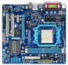
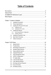
Table of Contents Box Contents...6 Optional Items...6 GA-M68M-S2P Motherboard Layout 7 Block Diagram...8 Chapter 1 Hardware Installation 9 1-1 Installation Precautions 9 1-2 Product Specifications 10 1-3 Installing the CPU and CPU Cooler 13 1-3-1 Installing the CPU 13 1-3-2 Installing the CPU Cooler 15 1-4 Installing the Memory 16 1-4-1 Dual Channel Memory Configuration 16 1-4-2 Installing a Memory 17 1-5 Installing an Expansion Card 18 1-6 Back Panel Connectors 19 1-7 Internal Connectors 21...
Table of Contents Box Contents...6 Optional Items...6 GA-M68M-S2P Motherboard Layout 7 Block Diagram...8 Chapter 1 Hardware Installation 9 1-1 Installation Precautions 9 1-2 Product Specifications 10 1-3 Installing the CPU and CPU Cooler 13 1-3-1 Installing the CPU 13 1-3-2 Installing the CPU Cooler 15 1-4 Installing the Memory 16 1-4-1 Dual Channel Memory Configuration 16 1-4-2 Installing a Memory 17 1-5 Installing an Expansion Card 18 1-6 Back Panel Connectors 19 1-7 Internal Connectors 21...
Manual
Page 5
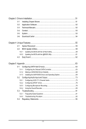
Chapter 3 Drivers Installation 51 3-1 Installing Chipset Drivers 51 3-2 Application Software 52 3-3 Technical Manuals 52 3-4 Contact...53 3-5 System...53 3-6 Download Center 54 Chapter 4 Unique Features 55 4-1 ...EasyTune 6...62 Chapter 5 Appendix...63 5-1 Configuring SATA Hard Drive(s 63 5-1-1 Configuring the Onboard SATA Controller 63 5-1-2 Making a SATA RAID Driver Diskette 68 5-1-3 Installing the SATA RAID Driver and Operating System 69 5-2 Configuring Audio Input and Output 73 5-2-1 Configuring 2/4/5.1/7.1-Channel Audio 73 5-2-2 Configuring S/PDIF In/Out 76 5-2-3 Configuring ...
Chapter 3 Drivers Installation 51 3-1 Installing Chipset Drivers 51 3-2 Application Software 52 3-3 Technical Manuals 52 3-4 Contact...53 3-5 System...53 3-6 Download Center 54 Chapter 4 Unique Features 55 4-1 ...EasyTune 6...62 Chapter 5 Appendix...63 5-1 Configuring SATA Hard Drive(s 63 5-1-1 Configuring the Onboard SATA Controller 63 5-1-2 Making a SATA RAID Driver Diskette 68 5-1-3 Installing the SATA RAID Driver and Operating System 69 5-2 Configuring Audio Input and Output 73 5-2-1 Configuring 2/4/5.1/7.1-Channel Audio 73 5-2-2 Configuring S/PDIF In/Out 76 5-2-3 Configuring ...
Manual
Page 9
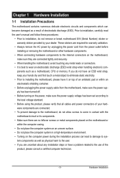
...• Turning on the motherboard, make sure they are connected tightly and securely. • When handling the motherboard, avoid touching any installation steps or have it on top of an antistatic pad or within an electrostatic shielding container. • Before unplugging the power supply cable...break motherboard S/N (Serial Number) sticker or warranty sticker provided by unplugging the power cord from the power outlet before installing or removing the motherboard or other hardware components. • When connecting hardware components to the internal connectors on the computer power ...
...• Turning on the motherboard, make sure they are connected tightly and securely. • When handling the motherboard, avoid touching any installation steps or have it on top of an antistatic pad or within an electrostatic shielding container. • Before unplugging the power supply cable...break motherboard S/N (Serial Number) sticker or warranty sticker provided by unplugging the power cord from the power outlet before installing or removing the motherboard or other hardware components. • When connecting hardware components to the internal connectors on the computer power ...
Manual
Page 10
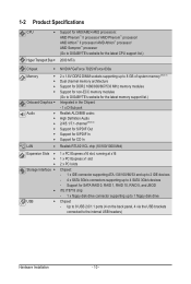
...II processor/ AMD Phenom™ processor/ AMD Athlon™ II processor/ AMD Athlon™ processor/ AMD Sempron™ processor (Go to GIGABYTE's website for the latest CPU support list.) 2000 MT/s Chipset NVIDIA® GeForce 7025/nForce 630a Memory Onboard Graphics ...1, RAID 10, RAID 5, and JBOD iTE IT8718 chip: - 1 x floppy disk drive connector supporting up to the internal USB headers) Hardware Installation - 10 - Support for CD In LAN Realtek RTL8211CL chip (10/100/1000 Mbit) Expansion Slots 1 x PCI Express x16 slot,...
...II processor/ AMD Phenom™ processor/ AMD Athlon™ II processor/ AMD Athlon™ processor/ AMD Sempron™ processor (Go to GIGABYTE's website for the latest CPU support list.) 2000 MT/s Chipset NVIDIA® GeForce 7025/nForce 630a Memory Onboard Graphics ...1, RAID 10, RAID 5, and JBOD iTE IT8718 chip: - 1 x floppy disk drive connector supporting up to the internal USB headers) Hardware Installation - 10 - Support for CD In LAN Realtek RTL8211CL chip (10/100/1000 Mbit) Expansion Slots 1 x PCI Express x16 slot,...

Manual
Page 11
Hardware Installation Internal Connectors Back Panel Connectors w 1 x 24-pin ATX main power connector w 1 x 4-pin ATX 12V power connector w 1 x floppy disk drive connector w 1 x IDE connector w 4 x SATA 3Gb/s connectors w 1 x ...
Hardware Installation Internal Connectors Back Panel Connectors w 1 x 24-pin ATX main power connector w 1 x 4-pin ATX 12V power connector w 1 x floppy disk drive connector w 1 x IDE connector w 4 x SATA 3Gb/s connectors w 1 x ...

Manual
Page 12
...w w w w w Bundled Software w Support for @BIOS Support for Q-Flash Support for Xpress BIOS Rescue Support for Download Center Support for Xpress Install Support for Xpress Recovery2 Support for EasyTune (Note 4) Norton Internet Security (OEM version) Operating System w Support for Microsoft® Windows® 7/Vista/...; 24.4cm x 22.5cm (Note 1) Due to Windows 32-bit operating system limitation, when more than 4 GB of physical memory is installed, the actual memory size displayed will be less than 4 GB. (Note 2) To configure 7.1-channel audio, you have to use an HD...
...w w w w w Bundled Software w Support for @BIOS Support for Q-Flash Support for Xpress BIOS Rescue Support for Download Center Support for Xpress Install Support for Xpress Recovery2 Support for EasyTune (Note 4) Norton Internet Security (OEM version) Operating System w Support for Microsoft® Windows® 7/Vista/...; 24.4cm x 22.5cm (Note 1) Due to Windows 32-bit operating system limitation, when more than 4 GB of physical memory is installed, the actual memory size displayed will be less than 4 GB. (Note 2) To configure 7.1-channel audio, you have to use an HD...
Manual
Page 13
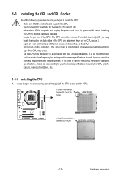
...specifications, please do so according to your hardware specifications including the CPU, graphics card, memory, hard drive, etc. 1-3-1 Installing the CPU A. A Small Triangle Mark Denotes Pin One of the Socket AM2 Socket A Small Triangle Marking Denotes CPU ...Pin One AM3/AM2+/AM2 CPU - 13 - If you begin to install the CPU: • Make sure that the system bus frequency be inserted if oriented incorrectly. (Or you may ...cooler is not recommended that the motherboard supports the CPU. (Go to GIGABYTE's website for the peripherals.
...specifications, please do so according to your hardware specifications including the CPU, graphics card, memory, hard drive, etc. 1-3-1 Installing the CPU A. A Small Triangle Mark Denotes Pin One of the Socket AM2 Socket A Small Triangle Marking Denotes CPU ...Pin One AM3/AM2+/AM2 CPU - 13 - If you begin to install the CPU: • Make sure that the system bus frequency be inserted if oriented incorrectly. (Or you may ...cooler is not recommended that the motherboard supports the CPU. (Go to GIGABYTE's website for the peripherals.
Manual
Page 14
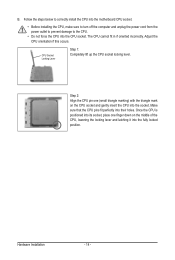
... CPU into the motherboard CPU socket. • Before installing the CPU, make sure to turn off the computer and unplug the power cord from the power outlet to prevent damage to the CPU. • ...Do not force the CPU into their holes. The CPU cannot fit in if oriented incorrectly. Hardware Installation - 14 - Make sure that the CPU pins fit perfectly into the CPU socket. Step 2: Align the CPU pin one finger down on the CPU socket...
... CPU into the motherboard CPU socket. • Before installing the CPU, make sure to turn off the computer and unplug the power cord from the power outlet to prevent damage to the CPU. • ...Do not force the CPU into their holes. The CPU cannot fit in if oriented incorrectly. Hardware Installation - 14 - Make sure that the CPU pins fit perfectly into the CPU socket. Step 2: Align the CPU pin one finger down on the CPU socket...
Manual
Page 15
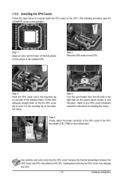
... 2: Place the CPU cooler on one side of the retention frame. Hardware Installation 1-3-2 Installing the CPU Cooler Follow the steps below to correctly install the CPU cooler on the CPU. (The following procedure uses the GIGABYTE cooler as the picture above shows) to lock into place. (Refer to ...your CPU cooler installation manual for instructions on installing the cooler.) Step 5: Finally, attach the...
... 2: Place the CPU cooler on one side of the retention frame. Hardware Installation 1-3-2 Installing the CPU Cooler Follow the steps below to correctly install the CPU cooler on the CPU. (The following procedure uses the GIGABYTE cooler as the picture above shows) to lock into place. (Refer to ...your CPU cooler installation manual for instructions on installing the cooler.) Step 5: Finally, attach the...
Manual
Page 16
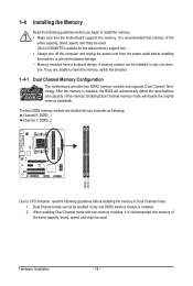
If you begin to install the memory: • Make sure that memory of the same capacity, brand, speed, and chips be enabled if only one direction. Dual Channel mode cannot be used . A memory module can be used . (Go to GIGABYTE's website for the latest memory support list.) &#...8226; Always turn off the computer and unplug the power cord from the power outlet before installing the memory to insert the memory, switch the direction. 1-4-1 Dual Channel Memory...
If you begin to install the memory: • Make sure that memory of the same capacity, brand, speed, and chips be enabled if only one direction. Dual Channel mode cannot be used . A memory module can be used . (Go to GIGABYTE's website for the latest memory support list.) &#...8226; Always turn off the computer and unplug the power cord from the power outlet before installing the memory to insert the memory, switch the direction. 1-4-1 Dual Channel Memory...

Manual
Page 17
...the memory, push down on the memory and insert it can only fit in the memory sockets. Place the memory module on this motherboard. Hardware Installation Spread the retaining clips at both ends of the socket will snap into the memory socket. Step 2: The clips at both ends of the memory... socket. Follow the steps below to correctly install your fingers on the top edge of the memory module. Notch DDR2 DIMM A DDR2 memory module has a notch, so it vertically into place when ...
...the memory, push down on the memory and insert it can only fit in the memory sockets. Place the memory module on this motherboard. Hardware Installation Spread the retaining clips at both ends of the socket will snap into the memory socket. Step 2: The clips at both ends of the memory... socket. Follow the steps below to correctly install your fingers on the top edge of the memory module. Notch DDR2 DIMM A DDR2 memory module has a notch, so it vertically into place when ...
Manual
Page 18
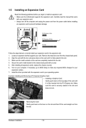
...from the chassis back panel. 2. Secure the card's metal bracket to make any required BIOS changes for your expansion card(s). 7. Install the driver provided with the slot, and press down on the top edge of the card until it is fully inserted into the ... a screw. 5. Carefully read the manual that supports your card. 1-5 Installing an Expansion Card Read the following guidelines before installing an expansion card to correctly install your expansion card in the expansion slot. 1. Hardware Installation - 18 - Align the card with the expansion card in your operating ...
...from the chassis back panel. 2. Secure the card's metal bracket to make any required BIOS changes for your expansion card(s). 7. Install the driver provided with the slot, and press down on the top edge of the card until it is fully inserted into the ... a screw. 5. Carefully read the manual that supports your card. 1-5 Installing an Expansion Card Read the following guidelines before installing an expansion card to correctly install your expansion card in the expansion slot. 1. Hardware Installation - 18 - Align the card with the expansion card in your operating ...

Manual
Page 19
... the parallel port to this port for USB devices such as a USB keyboard/mouse, USB printer, USB flash drive and etc. Use this port. Hardware Installation Connect a monitor that supports D-Sub connection to connect devices such as a mouse, modem or other peripherals. D-Sub Port The D-Sub port supports a 15-pin D-Sub...
... the parallel port to this port for USB devices such as a USB keyboard/mouse, USB printer, USB flash drive and etc. Use this port. Hardware Installation Connect a monitor that supports D-Sub connection to connect devices such as a mouse, modem or other peripherals. D-Sub Port The D-Sub port supports a 15-pin D-Sub...
Manual
Page 20
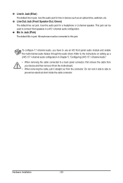
... the cable connected to prevent an electrical short inside the cable connector. Use this jack. Mic In Jack (Pink) The default Mic in jack. Hardware Installation - 20 -
... the cable connected to prevent an electrical short inside the cable connector. Use this jack. Mic In Jack (Pink) The default Mic in jack. Hardware Installation - 20 -

Manual
Page 21
... and before connecting external devices: • First make sure the device cable has been securely attached to turn off the devices and your computer. Hardware Installation 1-7 Internal Connectors 13 9 13 14 10 11 5 1) ATX_12V 2) ATX 3) CPU_FAN 4) SYS_FAN 5) FDD 6) IDE 7) SATA2_0/1/2/3 2 6 7 8 4 12 8) F_PANEL 9) F_AUDIO 10) CD_IN 11) SPDIF_IO 12) ... the following guidelines before turning on the computer, make sure your devices are compliant with the connectors you wish to connect. • Before installing the devices, be sure to the connector on the motherboard. - 21 -
... and before connecting external devices: • First make sure the device cable has been securely attached to turn off the devices and your computer. Hardware Installation 1-7 Internal Connectors 13 9 13 14 10 11 5 1) ATX_12V 2) ATX 3) CPU_FAN 4) SYS_FAN 5) FDD 6) IDE 7) SATA2_0/1/2/3 2 6 7 8 4 12 8) F_PANEL 9) F_AUDIO 10) CD_IN 11) SPDIF_IO 12) ... the following guidelines before turning on the computer, make sure your devices are compliant with the connectors you wish to connect. • Before installing the devices, be sure to the connector on the motherboard. - 21 -
Manual
Page 22
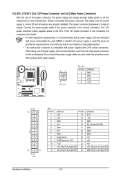
... withstand high power consumption be used that does not provide the required power, the result can supply enough stable power to all devices are properly installed. If a power supply is turned off and all the components on the motherboard. Do not insert the power supply cable into pins under the protective... -12V GND PS_ON (soft On/Off) GND GND GND -5V +5V +5V +5V (Only for 2x12-pin ATX) GND (Only for 2x12-pin ATX) Hardware Installation - 22 -
... withstand high power consumption be used that does not provide the required power, the result can supply enough stable power to all devices are properly installed. If a power supply is turned off and all the components on the motherboard. Do not insert the power supply cable into pins under the protective... -12V GND PS_ON (soft On/Off) GND GND GND -5V +5V +5V +5V (Only for 2x12-pin ATX) GND (Only for 2x12-pin ATX) Hardware Installation - 22 -
Manual
Page 23
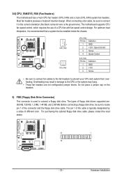
The types of different color. Hardware Installation 3/4) CPU_FAN/SYS_FAN (Fan Headers) The motherboard has a 4-pin CPU fan header (CPU_FAN) and a 3-pin (SYS_FAN) system fan headers. Most fan headers possess a foolproof insertion design. ... MB, and 2.88 MB. For optimum heat dissipation, it in damage to prevent your CPU and system from overheating. Before connecting a floppy disk drive, be installed inside the chassis. 1 CPU_FAN 1 SYS_FAN CPU_FAN: Pin No. The pin 1 of the cable is used to locate pin 1 of a CPU fan with fan speed control...
The types of different color. Hardware Installation 3/4) CPU_FAN/SYS_FAN (Fan Headers) The motherboard has a 4-pin CPU fan header (CPU_FAN) and a 3-pin (SYS_FAN) system fan headers. Most fan headers possess a foolproof insertion design. ... MB, and 2.88 MB. For optimum heat dissipation, it in damage to prevent your CPU and system from overheating. Before connecting a floppy disk drive, be installed inside the chassis. 1 CPU_FAN 1 SYS_FAN CPU_FAN: Pin No. The pin 1 of the cable is used to locate pin 1 of a CPU fan with fan speed control...

Manual
Page 24
.... If more than two hard drives are compatible with SATA 1.5Gb/s standard. Refer to two IDE devices such as hard drives and optical drives. Hardware Installation - 24 - 6) IDE (IDE Connector) The IDE connector supports up to Chapter 5, "Configuring SATA Hard Drive(s)," for the IDE devices, read the instructions from the device...
.... If more than two hard drives are compatible with SATA 1.5Gb/s standard. Refer to two IDE devices such as hard drives and optical drives. Hardware Installation - 24 - 6) IDE (IDE Connector) The IDE connector supports up to Chapter 5, "Configuring SATA Hard Drive(s)," for the IDE devices, read the instructions from the device...
Manual
Page 25
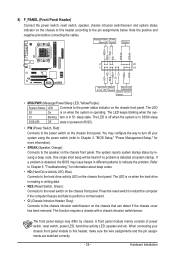
... (Message/Power/Sleep LED, Yellow/Purple): System Status LED Connects to the speaker on the chassis front panel. The LED S0 On is operating. Hardware Installation The LED is off (S5). • PW (Power Switch, Red): Connects to the power switch on when the system is on the chassis front panel...
... (Message/Power/Sleep LED, Yellow/Purple): System Status LED Connects to the speaker on the chassis front panel. The LED S0 On is operating. Hardware Installation The LED is off (S5). • PW (Power Switch, Red): Connects to the power switch on when the system is on the chassis front panel...

Manual
Page 26
... Pin 9 LINE2_L 9 Line Out (L) 10 GND 10 NC • The front panel audio header supports HD audio by default. Definition 1 CD-L 1 2 GND 3 GND 4 CD-R Hardware Installation - 26 - Make sure the wire assignments of the module connector match the pin assignments of a single plug. If your optical drive to work or even...
... Pin 9 LINE2_L 9 Line Out (L) 10 GND 10 NC • The front panel audio header supports HD audio by default. Definition 1 CD-L 1 2 GND 3 GND 4 CD-R Hardware Installation - 26 - Make sure the wire assignments of the module connector match the pin assignments of a single plug. If your optical drive to work or even...


