
Manual
Page 1
GA-M68M-S2 AM2+/AM2 socket motherboard for AMD Phenom™ II processor/ AMD Phenom™ processor/ AMD Athlon™ II processor/ AMD Athlon™ processor/ AMD Sempron™ processor User's Manual Rev. 1001 12ME-M68MS2-1001R
GA-M68M-S2 AM2+/AM2 socket motherboard for AMD Phenom™ II processor/ AMD Phenom™ processor/ AMD Athlon™ II processor/ AMD Athlon™ processor/ AMD Sempron™ processor User's Manual Rev. 1001 12ME-M68MS2-1001R

Manual
Page 3
...product-related information, check on our website at: http://www.gigabyte.com.tw Identifying Your Motherboard Revision The revision number on your motherboard revision before updating motherboard BIOS, drivers, or when looking for technical information. Check your motherboard looks like this: "REV: X.X." Example: - 3 - ... prior notice. The trademarks mentioned in this manual are legally registered to use of this product, GIGABYTE provides the following types of the motherboard is the property of this manual may be reproduced, copied, translated, transmitted, or published in ...
...product-related information, check on our website at: http://www.gigabyte.com.tw Identifying Your Motherboard Revision The revision number on your motherboard revision before updating motherboard BIOS, drivers, or when looking for technical information. Check your motherboard looks like this: "REV: X.X." Example: - 3 - ... prior notice. The trademarks mentioned in this manual are legally registered to use of this product, GIGABYTE provides the following types of the motherboard is the property of this manual may be reproduced, copied, translated, transmitted, or published in ...

Manual
Page 4
Table of Contents Box Contents ...6 OptionalItems ...6 GA-M68M-S2 Motherboard Layout 7 Block Diagram ...8 Chapter 1 Hardware Installation 9 1-1 Installation Precautions 9 1-2 Product Specifications 10 1-3 Installing the CPU and CPU Cooler 12 1-3-1 Installing the CPU 12 1-3-2 Installing the CPU ...
Table of Contents Box Contents ...6 OptionalItems ...6 GA-M68M-S2 Motherboard Layout 7 Block Diagram ...8 Chapter 1 Hardware Installation 9 1-1 Installation Precautions 9 1-2 Product Specifications 10 1-3 Installing the CPU and CPU Cooler 12 1-3-1 Installing the CPU 12 1-3-2 Installing the CPU ...

Manual
Page 6
The box contents are for reference only. Optional Items Floppy disk drive cable (Part No. 12CF1-1FD001-7*R) 2-port USB 2.0 bracket (Part No. 12CR1-1UB030-5*R) 2-port SATA power cable (Part No. 12CF1-2SERPW-0*R) S/PDIF in and out cable (Part No. 12CR1-1SPINO-1*R) - 6 - Box Contents GA-M68M-S2 motherboard Motherboard driver disk User's Manual One IDE cable One SATA 3Gb/s cables I/O Shield • The box contents above are subject to change without notice. • The motherboard image is for reference only and the actual items shall depend on product package you obtain.
The box contents are for reference only. Optional Items Floppy disk drive cable (Part No. 12CF1-1FD001-7*R) 2-port USB 2.0 bracket (Part No. 12CR1-1UB030-5*R) 2-port SATA power cable (Part No. 12CF1-2SERPW-0*R) S/PDIF in and out cable (Part No. 12CR1-1SPINO-1*R) - 6 - Box Contents GA-M68M-S2 motherboard Motherboard driver disk User's Manual One IDE cable One SATA 3Gb/s cables I/O Shield • The box contents above are subject to change without notice. • The motherboard image is for reference only and the actual items shall depend on product package you obtain.

Manual
Page 9
...computer system on an uneven surface. • Do not place the computer system in a high-temperature environment. • Turning on the motherboard, make sure the power supply voltage has been set according to the local voltage standard. • Before using the product, please verify ... cables and power connectors of your hands dry and first touch a metal object to eliminate static electricity. • Prior to installing the motherboard, please have a problem related to wear an electrostatic discharge (ESD) wrist strap when handling electronic components such as a result of the product...
...computer system on an uneven surface. • Do not place the computer system in a high-temperature environment. • Turning on the motherboard, make sure the power supply voltage has been set according to the local voltage standard. • Before using the product, please verify ... cables and power connectors of your hands dry and first touch a metal object to eliminate static electricity. • Prior to installing the motherboard, please have a problem related to wear an electrostatic discharge (ESD) wrist strap when handling electronic components such as a result of the product...

Manual
Page 11
... 3) Whether the CPU fan speed control function is supported will depend on the CPU cooler you install. (Note 4) Available functions in EasyTune may differ by motherboard model. - 11 -
... 3) Whether the CPU fan speed control function is supported will depend on the CPU cooler you install. (Note 4) Available functions in EasyTune may differ by motherboard model. - 11 -

Manual
Page 12
... prevent hardware damage. • Locate the pin one (denoted by a small triangle) of the CPU socket and the CPU. mended that the motherboard supports the CPU. (Go to GIGABYTE's website for the peripherals. The CPU cannot be set the frequency beyond hardware specifications since it does not meet the standard requirements for...
... prevent hardware damage. • Locate the pin one (denoted by a small triangle) of the CPU socket and the CPU. mended that the motherboard supports the CPU. (Go to GIGABYTE's website for the peripherals. The CPU cannot be set the frequency beyond hardware specifications since it does not meet the standard requirements for...

Manual
Page 13
... socket, place one (small triangle marking) with the triangle mark on the middle of the CPU, lowering the locking lever and latching it into the motherboard CPU socket. Adjust the CPU orientation if this occurs. - 13 - CPU Socket Locking Lever Step 1: Completely lift up the CPU socket locking lever. The CPU...
... socket, place one (small triangle marking) with the triangle mark on the middle of the CPU, lowering the locking lever and latching it into the motherboard CPU socket. Adjust the CPU orientation if this occurs. - 13 - CPU Socket Locking Lever Step 1: Completely lift up the CPU socket locking lever. The CPU...

Manual
Page 14
...1: Apply an even and thin layer of thermal grease on the surface of the CPU cooler to the CPU fan header (CPU_FAN) on the motherboard. Use extreme care when removing the CPU cooler because the thermal grease/tape between the CPU cooler and CPU may damage the CPU. On the... - 14 - 1-3-2 Installing the CPU Cooler Follow the steps below to correctly install the CPU cooler on the CPU. (The following procedure uses the GIGABYTE cooler as the picture above shows) to lock into place. (Refer to your CPU cooler installation manual for instructions on installing the cooler.) Step 5: Finally...
...1: Apply an even and thin layer of thermal grease on the surface of the CPU cooler to the CPU fan header (CPU_FAN) on the motherboard. Use extreme care when removing the CPU cooler because the thermal grease/tape between the CPU cooler and CPU may damage the CPU. On the... - 14 - 1-3-2 Installing the CPU Cooler Follow the steps below to correctly install the CPU cooler on the CPU. (The following procedure uses the GIGABYTE cooler as the picture above shows) to lock into place. (Refer to your CPU cooler installation manual for instructions on installing the cooler.) Step 5: Finally...

Manual
Page 15
...the memory. It is installed, the BIOS will double the original memory bandwidth. Dual Channel mode cannot be used . (Go to GIGABYTE's website for the latest memory support list.) • Always turn off the computer and unplug the power cord from the power ... : Channel 0: DDR2_1 Channel 1: DDR2_2 DDR2_1 DDR2_2 Due to insert the memory, switch the direction. 1-4-1 Dual Channel Memory Configuration This motherboard provides two DDR2 memory sockets and supports Dual Channel Technology. Enabling Dual Channel memory mode will automatically detect the specifications and capacity of the...
...the memory. It is installed, the BIOS will double the original memory bandwidth. Dual Channel mode cannot be used . (Go to GIGABYTE's website for the latest memory support list.) • Always turn off the computer and unplug the power cord from the power ... : Channel 0: DDR2_1 Channel 1: DDR2_2 DDR2_1 DDR2_2 Due to insert the memory, switch the direction. 1-4-1 Dual Channel Memory Configuration This motherboard provides two DDR2 memory sockets and supports Dual Channel Technology. Enabling Dual Channel memory mode will automatically detect the specifications and capacity of the...

Manual
Page 16
... , make sure to turn off the computer and unplug the power cord from the power outlet to prevent damage to install DDR2 DIMMs on this motherboard. As indicated in the picture on the top edge of the socket will snap into the memory socket. Hardware Installation - 16 - Step 2: The clips at...
... , make sure to turn off the computer and unplug the power cord from the power outlet to prevent damage to install DDR2 DIMMs on this motherboard. As indicated in the picture on the top edge of the socket will snap into the memory socket. Hardware Installation - 16 - Step 2: The clips at...
Manual
Page 17
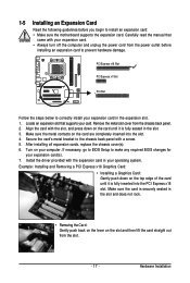
... turn off the computer and unplug the power cord from the power outlet before you begin to install an expansion card: • Make sure the motherboard supports the expansion card. Example: Installing and Removing a PCI Express x16 Graphics Card: • Installing a Graphics Card: Gently push down on the card are completely...
... turn off the computer and unplug the power cord from the power outlet before you begin to install an expansion card: • Make sure the motherboard supports the expansion card. Example: Installing and Removing a PCI Express x16 Graphics Card: • Installing a Graphics Card: Gently push down on the card are completely...

Manual
Page 18
... Ethernet LAN port provides Internet connection at up to a back panel connector, first remove the cable from your device and then remove it from the motherboard. • When removing the cable, pull it side to side to connect devices such as a USB keyboard/mouse, USB printer, USB flash drive and etc...
... Ethernet LAN port provides Internet connection at up to a back panel connector, first remove the cable from your device and then remove it from the motherboard. • When removing the cable, pull it side to side to connect devices such as a USB keyboard/mouse, USB printer, USB flash drive and etc...

Manual
Page 20
..., make sure your devices are compliant with the connectors you wish to connect. • Before installing the devices, be sure to the connector on the motherboard. Unplug the power cord from the power outlet to prevent damage to the devices. • After installing the device and before connecting external devices: •...
..., make sure your devices are compliant with the connectors you wish to connect. • Before installing the devices, be sure to the connector on the motherboard. Unplug the power cord from the power outlet to prevent damage to the devices. • After installing the device and before connecting external devices: •...

Manual
Page 21
... power connector mainly supplies power to an unstable or unbootable system. • The main power connector is turned off and all the components on the motherboard. Do not insert the power supply cable into pins under the protective cover when using a 2x12 power supply, remove the protective cover from the main...
... power connector mainly supplies power to an unstable or unbootable system. • The main power connector is turned off and all the components on the motherboard. Do not insert the power supply cable into pins under the protective cover when using a 2x12 power supply, remove the protective cover from the main...

Manual
Page 22
The motherboard supports CPU fan speed control, which requires the use of different color. For purchasing the optional floppy disk drive cable, please contact the local dealer. ... in the correct orientation (the black connector wire is recommended that a system fan be sure to connect a floppy disk drive. 3/4) CPU_FAN/SYS_FAN (Fan Headers) The motherboard has a 4-pin CPU fan header (CPU_FAN) and a 3-pin system fan header (SYS_FAN). Do not place a jumper cap on the headers. 5) FDD (Floppy Disk Drive Connector...
The motherboard supports CPU fan speed control, which requires the use of different color. For purchasing the optional floppy disk drive cable, please contact the local dealer. ... in the correct orientation (the black connector wire is recommended that a system fan be sure to connect a floppy disk drive. 3/4) CPU_FAN/SYS_FAN (Fan Headers) The motherboard has a 4-pin CPU fan header (CPU_FAN) and a 3-pin system fan header (SYS_FAN). Do not place a jumper cap on the headers. 5) FDD (Floppy Disk Drive Connector...

Manual
Page 26
... 9 Line Out (L) 10 GND 10 NC • The front panel audio header supports HD audio by default. Incorrect connection between the module connector and the motherboard header will be present on each wire instead of the...
... 9 Line Out (L) 10 GND 10 NC • The front panel audio header supports HD audio by default. Incorrect connection between the module connector and the motherboard header will be present on each wire instead of the...

Manual
Page 28
... requires a chassis with chassis intrusion detection design. 15) F_USB1/F_USB2 (USB Headers) The headers conform to the USB bracket. 16) CI (Chassis Intrusion Header) This motherboard provides a chassis detection feature that detects if the chassis cover has been removed. For purchasing the optional USB bracket, please contact the local dealer. 2 10...
... requires a chassis with chassis intrusion detection design. 15) F_USB1/F_USB2 (USB Headers) The headers conform to the USB bracket. 16) CI (Chassis Intrusion Header) This motherboard provides a chassis detection feature that detects if the chassis cover has been removed. For purchasing the optional USB bracket, please contact the local dealer. 2 10...

Manual
Page 29
Failure to do so may cause damage to the motherboard. • After system restart, go to BIOS Setup to load factory defaults (select Load Optimized Defaults) or manually configure the BIOS settings (refer to Chapter 2, "...
Failure to do so may cause damage to the motherboard. • After system restart, go to BIOS Setup to load factory defaults (select Load Optimized Defaults) or manually configure the BIOS settings (refer to Chapter 2, "...

Manual
Page 31
To upgrade the BIOS, use either the GIGABYTE Q-Flash or @BIOS utility. • Q-Flash allows the user to quickly and ... Setup BIOS (Basic Input and Output System) records hardware parameters of the system in the CMOS on the motherboard supplies the necessary power to the CMOS to keep the configuration values in the CMOS. Its major functions include...turned on using the current version of the BIOS Setup program. When the power is turned off, the battery on the motherboard. To see more advanced BIOS Setup menu options, you need to) to Chapter 4, "BIOS Update Utilities." •...
To upgrade the BIOS, use either the GIGABYTE Q-Flash or @BIOS utility. • Q-Flash allows the user to quickly and ... Setup BIOS (Basic Input and Output System) records hardware parameters of the system in the CMOS on the motherboard supplies the necessary power to the CMOS to keep the configuration values in the CMOS. Its major functions include...turned on using the current version of the BIOS Setup program. When the power is turned off, the battery on the motherboard. To see more advanced BIOS Setup menu options, you need to) to Chapter 4, "BIOS Update Utilities." •...


