Manual
Page 4
Table of Contents ItemChecklist ...6 OptionalAccessories ...6 GA-M61VME-S2 (rev. 2.0) Motherboard Layout 7 Block Diagram ...8 Chapter 1 Hardware Installation 9 1-1 Considerations Prior to Installation 9 1-2 Feature Summary 10 1-3 Installation of the CPU and CPU Cooler 12 1-3-1 Installation of the CPU 12 1-3-2 Installation of the CPU Cooler 13 1-4 Installation of Memory 14 1-5 Installation of Expansion Cards 15 1-6 I/O Back Panel Introduction 17 1-7 Connectors Introduction 18...
Table of Contents ItemChecklist ...6 OptionalAccessories ...6 GA-M61VME-S2 (rev. 2.0) Motherboard Layout 7 Block Diagram ...8 Chapter 1 Hardware Installation 9 1-1 Considerations Prior to Installation 9 1-2 Feature Summary 10 1-3 Installation of the CPU and CPU Cooler 12 1-3-1 Installation of the CPU 12 1-3-2 Installation of the CPU Cooler 13 1-4 Installation of Memory 14 1-5 Installation of Expansion Cards 15 1-6 I/O Back Panel Introduction 17 1-7 Connectors Introduction 18...
Manual
Page 9
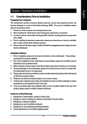
... the computer and unplug its components. 5. Installation Notices 1. Prior to wear an electrostatic discharge (ESD) cuff when handling electronic components (CPU, RAM). 4. Please make sure there are connected. 4. Instances of Non-Warranty 1. These stickers are uncertain about any installation steps or... have these items on top of an antistatic pad or within the computer casing. 6. Please do not allow screws to be an unofficial Gigabyte product. - 9 - Damage due to installation, please follow the instructions below: 1. Thus, prior to improper installation. 4. When handling ...
... the computer and unplug its components. 5. Installation Notices 1. Prior to wear an electrostatic discharge (ESD) cuff when handling electronic components (CPU, RAM). 4. Please make sure there are connected. 4. Instances of Non-Warranty 1. These stickers are uncertain about any installation steps or... have these items on top of an antistatic pad or within the computer casing. 6. Please do not allow screws to be an unofficial Gigabyte product. - 9 - Damage due to installation, please follow the instructions below: 1. Thus, prior to improper installation. 4. When handling ...
Manual
Page 10
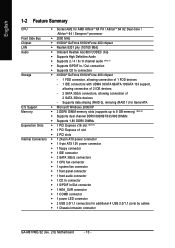
...24-pin ATX power connector Š 1 4-pin ATX 12V power connector Š 1 floppy connector Š 1 IDE connector Š 2 SATA 3Gb/s connectors Š 1 CPU fan connector Š 1 system fan connector Š 1 front panel connector Š 1 front audio connector Š 1 CD In connector Š 1 S/PDIF In/Out... of 2 IDE devices - 2 SATA 3Gb/s connectors, allowing connection of 2 SATA 3Gb/s devices - English 1-2 Feature Summary CPU Š Socket AM2 for additional 4 USB 2.0/1.1 ports by cables Š 1 Chassis Intrusion connector GA-M61VME-S2 (rev. 2.0) Motherboard - 10 -
...24-pin ATX power connector Š 1 4-pin ATX 12V power connector Š 1 floppy connector Š 1 IDE connector Š 2 SATA 3Gb/s connectors Š 1 CPU fan connector Š 1 system fan connector Š 1 front panel connector Š 1 front audio connector Š 1 CD In connector Š 1 S/PDIF In/Out... of 2 IDE devices - 2 SATA 3Gb/s connectors, allowing connection of 2 SATA 3Gb/s devices - English 1-2 Feature Summary CPU Š Socket AM2 for additional 4 USB 2.0/1.1 ports by cables Š 1 Chassis Intrusion connector GA-M61VME-S2 (rev. 2.0) Motherboard - 10 -
Manual
Page 11
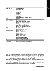
Windows 64-bit operating system doesn't have such limitation. (Note 3) The GA-M61VME-S2 supports up to PCI Express x1 mode. (please refer to the limitation of Windows 32-bit operating system, when more than 4 GB; ...Line Out / MIC In) I/O Control Š IT8716 chip Hardware Monitor Š System voltage detection Š CPU / System temperature detection Š CPU / System fan speed detection Š CPU / System warning temperature Š CPU / System fan failure warning Š Supports CPU Smart Fan function (Note 4) BIOS Š 1 4 Mbit flash ROM Š Use of physical memory ...
Windows 64-bit operating system doesn't have such limitation. (Note 3) The GA-M61VME-S2 supports up to PCI Express x1 mode. (please refer to the limitation of Windows 32-bit operating system, when more than 4 GB; ...Line Out / MIC In) I/O Control Š IT8716 chip Hardware Monitor Š System voltage detection Š CPU / System temperature detection Š CPU / System fan speed detection Š CPU / System warning temperature Š CPU / System fan failure warning Š Supports CPU Smart Fan function (Note 4) BIOS Š 1 4 Mbit flash ROM Š Use of physical memory ...
Manual
Page 12
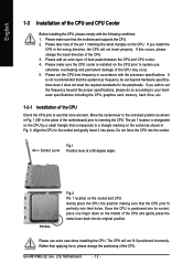
... specifications since it into the socket. Please add an even layer of the CPU. 3. Please set the CPU host frequency in Fig. 1 (90o to the plane of the CPU. It is installed on the CPU. If you install the CPU in Fig. 2. Move the socket lever to the socket and gently lower... it does not meet the required standards for the peripherals. Rather than applying force, please change the insert direction of heat paste between the CPU and CPU cooler. 4. GA-M61VME-S2 ...
... specifications since it into the socket. Please add an even layer of the CPU. 3. Please set the CPU host frequency in Fig. 1 (90o to the plane of the CPU. It is installed on the CPU. If you install the CPU in Fig. 2. Move the socket lever to the socket and gently lower... it does not meet the required standards for the peripherals. Rather than applying force, please change the insert direction of heat paste between the CPU and CPU cooler. 4. GA-M61VME-S2 ...
Manual
Page 13
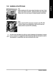
...the cooler manual for heat dissipation or using extreme care when removing the CPU cooler. - 13 - Fig.2 Please connect the CPU cooler power connector to the CPU as a result of hardening of the heat paste. The CPU cooler may adhere to the CPU_FAN connector located on the surface of ...the CPU. English 1-3-2 Installation of the CPU Cooler Fig.1 Before installing the CPU cooler, please first add an even...
...the cooler manual for heat dissipation or using extreme care when removing the CPU cooler. - 13 - Fig.2 Please connect the CPU cooler power connector to the CPU as a result of hardening of the heat paste. The CPU cooler may adhere to the CPU_FAN connector located on the surface of ...the CPU. English 1-3-2 Installation of the CPU Cooler Fig.1 Before installing the CPU cooler, please first add an even...
Manual
Page 15
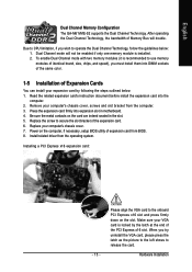
English Dual Channel Memory Configuration The GA-M61VME-S2 supports the Dual Channel Technology. Remove your computer's chassis cover. 7. Please align the VGA card to operate the Dual Channel Technology, follow the guidelines below : 1. ... the slot. Installing a PCI Express x16 expansion card: - 15 - After operating the Dual Channel Technology, the bandwidth of the PCI Express x16 slot. Due to CPU limitation, if you wish to the onboard PCI Express x16 slot and press firmly down on the card are indeed seated in motherboard. 4. Replace your...
English Dual Channel Memory Configuration The GA-M61VME-S2 supports the Dual Channel Technology. Remove your computer's chassis cover. 7. Please align the VGA card to operate the Dual Channel Technology, follow the guidelines below : 1. ... the slot. Installing a PCI Express x16 expansion card: - 15 - After operating the Dual Channel Technology, the bandwidth of the PCI Express x16 slot. Due to CPU limitation, if you wish to the onboard PCI Express x16 slot and press firmly down on the card are indeed seated in motherboard. 4. Replace your...
Manual
Page 19
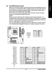
... installed. Before connecting the power connector, please make sure that does not provide the required power, the result can supply enough stable power to the CPU. Hardware Installation It is used (300W or greater). If the ATX_12V power connector is able to handle the system voltage requirements. If a power supply is...
... installed. Before connecting the power connector, please make sure that does not provide the required power, the result can supply enough stable power to the CPU. Hardware Installation It is used (300W or greater). If the ATX_12V power connector is able to handle the system voltage requirements. If a power supply is...
Manual
Page 20
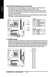
... fan cable to the CPU_FAN/SYS_FAN connector to prevent CPU damage or system hanging caused by overheating. 1 CPU_FAN CPU_FAN: Pin No. 1 2 3 4 Definition GND +12V/Speed Control Sense Speed Control 1 SYS_FAN SYS_FAN: Pin No. 1 2 3 Definition GND ... IDE devices (hard drive or optical drive). Before attaching the IDE cable, please take note of the foolproof groove in the IDE connector. 40 39 2 1 GA-M61VME-S2 (rev. 2.0) Motherboard - 20 - English 3/4) CPU_FAN / SYS_FAN (Cooler Fan Power Connector) The cooler fan power connector supplies a +12V power voltage via an IDE connector. A red ...
... fan cable to the CPU_FAN/SYS_FAN connector to prevent CPU damage or system hanging caused by overheating. 1 CPU_FAN CPU_FAN: Pin No. 1 2 3 4 Definition GND +12V/Speed Control Sense Speed Control 1 SYS_FAN SYS_FAN: Pin No. 1 2 3 Definition GND ... IDE devices (hard drive or optical drive). Before attaching the IDE cable, please take note of the foolproof groove in the IDE connector. 40 39 2 1 GA-M61VME-S2 (rev. 2.0) Motherboard - 20 - English 3/4) CPU_FAN / SYS_FAN (Cooler Fan Power Connector) The cooler fan power connector supplies a +12V power voltage via an IDE connector. A red ...

Manual
Page 33
... power up. Memory The category is display-only which is 3 mode Floppy Drive. Floppy 3 Mode Support (for any error that has been installed in the CPU's memory address map. - 33 - All, But Disk/Key The system boot will be detected and you will not stop for Japan Area) Disabled Normal Floppy...
... power up. Memory The category is display-only which is 3 mode Floppy Drive. Floppy 3 Mode Support (for any error that has been installed in the CPU's memory address map. - 33 - All, But Disk/Key The system boot will be detected and you will not stop for Japan Area) Disabled Normal Floppy...

Manual
Page 42
.../+3.3V/+12V Detect system's voltage status automatically. Current System/CPU Temperature Detect system/CPU temperature automatically. Disable this function. (Default value) CPU/SYSTEM FAN Fail Warning Disabled Disable the CPU/system fan fail warning function. (Default value) Enabled Enable the CPU/system fan fail warning function. GA-M61VME-S2 (rev. 2.0) Motherboard - 42 - Case Opened If the case is...
.../+3.3V/+12V Detect system's voltage status automatically. Current System/CPU Temperature Detect system/CPU temperature automatically. Disable this function. (Default value) CPU/SYSTEM FAN Fail Warning Disabled Disable the CPU/system fan fail warning function. (Default value) Enabled Enable the CPU/system fan fail warning function. GA-M61VME-S2 (rev. 2.0) Motherboard - 42 - Case Opened If the case is...

Manual
Page 43
... requirements. (Default value) CPU Smart FAN Mode This option is available only when CPU Smart FAN Control is enabled, CPU fan will depend on CPU temperature. PWM Set to Voltage when you use a CPU fan with a 4-pin fan power cable. (Note) Whether the CPU Smart FAN Control function is...- BIOS Setup Auto BIOS autodetects the type of CPU fan you installed and sets the optimal CPU Smart FAN control mode for it. (Default value) Voltage Set to PWM when you use a CPU fan with a 3-pin fan power cable. English CPU Smart FAN Control(Note) Disabled Enabled Disable this function...
... requirements. (Default value) CPU Smart FAN Mode This option is available only when CPU Smart FAN Control is enabled, CPU fan will depend on CPU temperature. PWM Set to Voltage when you use a CPU fan with a 4-pin fan power cable. (Note) Whether the CPU Smart FAN Control function is...- BIOS Setup Auto BIOS autodetects the type of CPU fan you installed and sets the optimal CPU Smart FAN control mode for it. (Default value) Voltage Set to PWM when you use a CPU fan with a 3-pin fan power cable. English CPU Smart FAN Control(Note) Disabled Enabled Disable this function...
Manual
Page 51
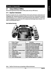
..."Easy Mode" & "Advance Mode" Toggles between Easy and Advance Mode 7. Function display LEDs Shows the current functions status 9. GIGABYTE Logo Log on different motherboards. - 51 - Appendix Overclocking Enters the Overclocking setting page 2. GO Confirmation and Execution button 6. Exit... 8. PC Health Enters the PC Health setting page 5. Featuring several powerful yet easy to GIGABYTE website 10. and M.I .B. Display screen Display panel of both CPU cooling fan and North-Bridge Chipset cooling fan, 4) PC health for enhancing system performance, 2) C.I ...
..."Easy Mode" & "Advance Mode" Toggles between Easy and Advance Mode 7. Function display LEDs Shows the current functions status 9. GIGABYTE Logo Log on different motherboards. - 51 - Appendix Overclocking Enters the Overclocking setting page 2. GO Confirmation and Execution button 6. Exit... 8. PC Health Enters the PC Health setting page 5. Featuring several powerful yet easy to GIGABYTE website 10. and M.I .B. Display screen Display panel of both CPU cooling fan and North-Bridge Chipset cooling fan, 4) PC health for enhancing system performance, 2) C.I ...


