
Manual
Page 1
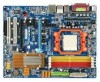
GA-M57SLI-S4 AMD AthlonTM 64 FX / AthlonTM 64 X2 Dual-Core / AMD AthlonTM 64 / SempronTM AM2 Processor Motherboard User's Manual Rev. 2002 12ME-M57SLI4R-2002R * The WEEE marking on the product indicates this product must not be disposed of with user's other household waste and must be handed over to a designated collection point for the recycling of waste electrical and electronic equipment!! * The WEEE marking applies only in European Union's member states.
GA-M57SLI-S4 AMD AthlonTM 64 FX / AthlonTM 64 X2 Dual-Core / AMD AthlonTM 64 / SempronTM AM2 Processor Motherboard User's Manual Rev. 2002 12ME-M57SLI4R-2002R * The WEEE marking on the product indicates this product must not be disposed of with user's other household waste and must be handed over to a designated collection point for the recycling of waste electrical and electronic equipment!! * The WEEE marking applies only in European Union's member states.
Manual
Page 4
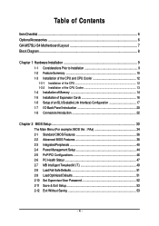
Table of Contents ItemChecklist ...6 OptionalAccessories ...6 GA-M57SLI-S4 Motherboard Layout 7 Block Diagram ...8 Chapter 1 Hardware Installation 9 1-1 Considerations Prior to Installation 9 1-2 Feature Summary 10 1-3 Installation of the CPU and CPU Cooler 12 1-3-1 Installation of the CPU ...
Table of Contents ItemChecklist ...6 OptionalAccessories ...6 GA-M57SLI-S4 Motherboard Layout 7 Block Diagram ...8 Chapter 1 Hardware Installation 9 1-1 Considerations Prior to Installation 9 1-2 Feature Summary 10 1-3 Installation of the CPU and CPU Cooler 12 1-3-1 Installation of the CPU ...

Manual
Page 9
...handling electronic components (CPU, RAM). 4. Please do not remove the stickers on the motherboard. Damage due to be an unofficial Gigabyte product. - 9 - When handling the motherboard, avoid touching any hardware, please first carefully read the information in the provided manual...electrostatic discharge (ESD). Damage as a result of uncertified components. 5. Instances of violating the conditions recommended in contact with the motherboard circuit or its power cord. 2. Product determined to natural disaster, accident or human cause. 2. Thus, prior to improper installation...
...handling electronic components (CPU, RAM). 4. Please do not remove the stickers on the motherboard. Damage due to be an unofficial Gigabyte product. - 9 - When handling the motherboard, avoid touching any hardware, please first carefully read the information in the provided manual...electrostatic discharge (ESD). Damage as a result of uncertified components. 5. Instances of violating the conditions recommended in contact with the motherboard circuit or its power cord. 2. Product determined to natural disaster, accident or human cause. 2. Thus, prior to improper installation...
Manual
Page 10
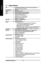
... connection of 6 SATA 3Gb/s devices - English 1-2 Feature Summary CPU Š Socket AM2 for additional 2 ports by cables Š 1 chassis intrusion connector Š 1 power LED connector GA-M57SLI-S4 Motherboard - 10 - Supports RAID 0, RAID 1, RAID 0+1, and RAID 5 for Serial ATA O.S Support Š Microsoft Windows Vista/2000/XP Memory Š 4 DDRII DIMM memory slots (supports up...
... connection of 6 SATA 3Gb/s devices - English 1-2 Feature Summary CPU Š Socket AM2 for additional 2 ports by cables Š 1 chassis intrusion connector Š 1 power LED connector GA-M57SLI-S4 Motherboard - 10 - Supports RAID 0, RAID 1, RAID 0+1, and RAID 5 for Serial ATA O.S Support Š Microsoft Windows Vista/2000/XP Memory Š 4 DDRII DIMM memory slots (supports up...
Manual
Page 11
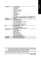
... is installed, the actual memory available for the operating system will depend on the CPU you install. (Note 3) EasyTune functions may vary depending on different motherboards. - 11 -
... is installed, the actual memory available for the operating system will depend on the CPU you install. (Note 3) EasyTune functions may vary depending on different motherboards. - 11 -
Manual
Page 12
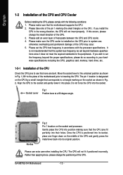
... as shown in accordance with the following conditions: 1. Please make sure that the CPU pins fit perfectly into position making sure that the motherboard supports the CPU. 2. Move the socket lever to set the CPU host frequency in Fig. 2. The pin 1 location is positioned into... metal lever back into its original position. Please set the frequency beyond hardware specifications since it into the socket. GA-M57SLI-S4 Motherboard - 12 - English 1-3 Installation of the CPU and CPU Cooler Before installing the CPU, please comply with the processor specifications.
... as shown in accordance with the following conditions: 1. Please make sure that the CPU pins fit perfectly into position making sure that the motherboard supports the CPU. 2. Move the socket lever to set the CPU host frequency in Fig. 2. The pin 1 location is positioned into... metal lever back into its original position. Please set the frequency beyond hardware specifications since it into the socket. GA-M57SLI-S4 Motherboard - 12 - English 1-3 Installation of the CPU and CPU Cooler Before installing the CPU, please comply with the processor specifications.

Manual
Page 13
English 1-3-2 Installation of the CPU Cooler Fig.1 Before installing the CPU cooler, please first add an even layer of heat paste on the motherboard so that the CPU cooler can properly function to the CPU. Use extreme care when removing the CPU cooler because the thermal grease/tape between ...
English 1-3-2 Installation of the CPU Cooler Fig.1 Before installing the CPU cooler, please first add an even layer of heat paste on the motherboard so that the CPU cooler can properly function to the CPU. Use extreme care when removing the CPU cooler because the thermal grease/tape between ...

Manual
Page 14
Before installing or removing memory modules, please make sure that they can be inserted only in one direction. The motherboard supports DDRII memory modules, whereby BIOS will automatically detect memory capacity and specifications. Notch DDRII Fig.1 The DIMM socket ... DIMM module. Insert the DIMM memory module vertically into the DIMM socket. GA-M57SLI-S4 Motherboard - 14 - Memory modules have a foolproof insertion design. It is recommended that the computer power is supported by the motherboard. Fig.2 Close the plastic clip at both edges of Memory Before installing the...
Before installing or removing memory modules, please make sure that they can be inserted only in one direction. The motherboard supports DDRII memory modules, whereby BIOS will automatically detect memory capacity and specifications. Notch DDRII Fig.1 The DIMM socket ... DIMM module. Insert the DIMM memory module vertically into the DIMM socket. GA-M57SLI-S4 Motherboard - 14 - Memory modules have a foolproof insertion design. It is recommended that the computer power is supported by the motherboard. Fig.2 Close the plastic clip at both edges of Memory Before installing the...

Manual
Page 16
...screws and slot bracket from its power source and read the expansion card's installation manual before installing the expansion card in the computer. 2. GA-M57SLI-S4 Motherboard - 16 - Press the expansion card firmly into the expansion slot in the operating system. Make sure the metal contacts on the card... BIOS Setup. 8. Or you try to the onboard PCI Express x16 slot. Disconnect your computer's chassis cover. 7. The motherboard includes a PCIE_12V power connector, which provides extra power to uninstall the VGA card. Power on the opposite side of the expansion card. 6....
...screws and slot bracket from its power source and read the expansion card's installation manual before installing the expansion card in the computer. 2. GA-M57SLI-S4 Motherboard - 16 - Press the expansion card firmly into the expansion slot in the operating system. Make sure the metal contacts on the card... BIOS Setup. 8. Or you try to the onboard PCI Express x16 slot. Disconnect your computer's chassis cover. 7. The motherboard includes a PCIE_12V power connector, which provides extra power to uninstall the VGA card. Power on the opposite side of the expansion card. 6....

Manual
Page 18
... to securely fix the bridge connector beween the two cards, you must install the retention bracket included with the motherboard and secure the retention bracket to the chassis back panel with a screw. GA-M57SLI-S4 Motherboard - 18 - retention bracket Step 4: Plug the display cable into the graphics card on the PCIE_16_1 slot(Note). (Note) To...
... to securely fix the bridge connector beween the two cards, you must install the retention bracket included with the motherboard and secure the retention bracket to the chassis back panel with a screw. GA-M57SLI-S4 Motherboard - 18 - retention bracket Step 4: Plug the display cable into the graphics card on the PCIE_16_1 slot(Note). (Note) To...
Manual
Page 20
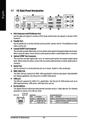
... 1394a specification, featuring high speed, high bandwidth and hotplug capabilities. USB port The USB port supports the USB 2.0/1.1 specification. The parallel port is not established GA-M57SLI-S4 Motherboard - 20 - Before using this feature, ensure that your audio system provides an optical digital audio in connector. Optical S/PDIF Out Connector This connector provides digital...
... 1394a specification, featuring high speed, high bandwidth and hotplug capabilities. USB port The USB port supports the USB 2.0/1.1 specification. The parallel port is not established GA-M57SLI-S4 Motherboard - 20 - Before using this feature, ensure that your audio system provides an optical digital audio in connector. Optical S/PDIF Out Connector This connector provides digital...

Manual
Page 22
English 1-8 Connectors Introduction 314 6 2 8 9 13 9 15 14 19 10 16 5 7 17 18 12 11 1) ATX_12V 2) ATX (Power Connector) 3) PCIE_12V 4) CPU_FAN 5) SYS_FAN 6) PWR_FAN 7) FDD 8) IDE1 9) SATAII1 / 2 / 3 / 4 / 5 / 6 10) BATTERY 11) F_PANEL 12) PWR_LED 13) F_AUDIO 14) CD_IN 15) SPDIF_I 16) F_USB1 / F_USB2 / F_USB3 17) F1_1394 / F2_1394 18) CI 19) CLR_CMOS GA-M57SLI-S4 Motherboard - 22 -
English 1-8 Connectors Introduction 314 6 2 8 9 13 9 15 14 19 10 16 5 7 17 18 12 11 1) ATX_12V 2) ATX (Power Connector) 3) PCIE_12V 4) CPU_FAN 5) SYS_FAN 6) PWR_FAN 7) FDD 8) IDE1 9) SATAII1 / 2 / 3 / 4 / 5 / 6 10) BATTERY 11) F_PANEL 12) PWR_LED 13) F_AUDIO 14) CD_IN 15) SPDIF_I 16) F_USB1 / F_USB2 / F_USB3 17) F1_1394 / F2_1394 18) CI 19) CLR_CMOS GA-M57SLI-S4 Motherboard - 22 -

Manual
Page 23
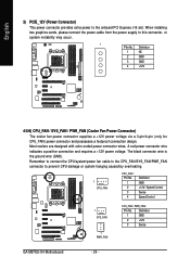
... use a 24-pin ATX power supply, please remove the small cover on the power connector on the motherboard and connect tightly. Align the power connector with its proper location on the motherboard before plugging in the power cord; If you use a power supply that can lead to an unstable system... or a system that all the components on the motherboard. It is recommended that a power supply that is unable to ...
... use a 24-pin ATX power supply, please remove the small cover on the power connector on the motherboard and connect tightly. Align the power connector with its proper location on the motherboard before plugging in the power cord; If you use a power supply that can lead to an unstable system... or a system that all the components on the motherboard. It is recommended that a power supply that is unable to ...
Manual
Page 24
... cooler fan power connector supplies a +12V power voltage via a 3-pin/4-pin (only for CPU_FAN) power connector and possesses a foolproof connection design. Definition 1 GND 2 +12V 3 Sense GA-M57SLI-S4 Motherboard - 24 - Remember to connect the CPU/system/power fan cable to the CPU_FAN/SYS_FAN/PWR_FAN connector to prevent CPU damage or system hanging caused by...
... cooler fan power connector supplies a +12V power voltage via a 3-pin/4-pin (only for CPU_FAN) power connector and possesses a foolproof connection design. Definition 1 GND 2 +12V 3 Sense GA-M57SLI-S4 Motherboard - 24 - Remember to connect the CPU/system/power fan cable to the CPU_FAN/SYS_FAN/PWR_FAN connector to prevent CPU damage or system hanging caused by...
Manual
Page 26
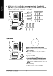
...'s instructions. Plug the power cord in order to work properly. 7 1 SATAII6 SATAII5 SATAII4 Pin No. 1 2 3 4 5 6 7 Definition GND TXP TXN GND RXN RXP GND 1 7 10) BATTERY GA-M57SLI-S4 Motherboard Danger of used batteries according to erase CMOS... 1. English SATAII1 SATAII2 SATAII3 9) SATAII1 / 2 / 3 / 4 / 5 / 6 (SATA 3Gb/s Connectors, Controlled by the manufacturer. Please refer to 300 MB...
...'s instructions. Plug the power cord in order to work properly. 7 1 SATAII6 SATAII5 SATAII4 Pin No. 1 2 3 4 5 6 7 Definition GND TXP TXN GND RXN RXP GND 1 7 10) BATTERY GA-M57SLI-S4 Motherboard Danger of used batteries according to erase CMOS... 1. English SATAII1 SATAII2 SATAII3 9) SATAII1 / 2 / 3 / 4 / 5 / 6 (SATA 3Gb/s Connectors, Controlled by the manufacturer. Please refer to 300 MB...
Manual
Page 28
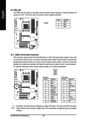
... Connector) This connector supports either HD (High Definition) or AC97 front panel audio module. To connect an AC97 front panel audio module to this connector. GA-M57SLI-S4 Motherboard - 28 - Pin No. Check the pin assignments carefully while you wish to use the front audio function, connect the front panel audio module to indicate...
... Connector) This connector supports either HD (High Definition) or AC97 front panel audio module. To connect an AC97 front panel audio module to this connector. GA-M57SLI-S4 Motherboard - 28 - Pin No. Check the pin assignments carefully while you wish to use the front audio function, connect the front panel audio module to indicate...

Manual
Page 30
... features like high speed, high bandwidth and hot plug. Definition 2 10 1 9 1 TPA+ 2 TPA- 3 GND 4 GND 5 TPB+ 6 TPB- 7 Power (12V) 8 Power (12V) 9 No Pin 10 GND GA-M57SLI-S4 Motherboard - 30 - For optional front USB cable, please contact your local dealer. Pin No. English 16) F_ USB1 / F_USB2 / F_USB3 (Front USB Connector) Be careful with...
... features like high speed, high bandwidth and hot plug. Definition 2 10 1 9 1 TPA+ 2 TPA- 3 GND 4 GND 5 TPB+ 6 TPB- 7 Power (12V) 8 Power (12V) 9 No Pin 10 GND GA-M57SLI-S4 Motherboard - 30 - For optional front USB cable, please contact your local dealer. Pin No. English 16) F_ USB1 / F_USB2 / F_USB3 (Front USB Connector) Be careful with...

Manual
Page 33
...or to select item Select Item Main Menu - The CMOS SETUP saves the configuration in system malfunction. - 33 - If you to a new BIOS, either Gigabyte's Q-Flash or @BIOS utility can enter the BIOS setup screen by pressing "Ctrl + F1". Q-Flash allows the user to quickly and easily update or ...it with caution and avoid inadequate operation that does not require users to boot to the CMOS SRAM. CMOS Profiles Main Menu The on the motherboard supplies the necessary power to DOS before upgrading BIOS but directly download and update BIOS from BIOS - Because BIOS flashing is turned off, ...
...or to select item Select Item Main Menu - The CMOS SETUP saves the configuration in system malfunction. - 33 - If you to a new BIOS, either Gigabyte's Q-Flash or @BIOS utility can enter the BIOS setup screen by pressing "Ctrl + F1". Q-Flash allows the user to quickly and easily update or ...it with caution and avoid inadequate operation that does not require users to boot to the CMOS SRAM. CMOS Profiles Main Menu The on the motherboard supplies the necessary power to DOS before upgrading BIOS but directly download and update BIOS from BIOS - Because BIOS flashing is turned off, ...
Manual
Page 34
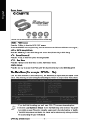
This action makes the system reset to BIOS F12: Load CMOS from the exact settings for your motherboard. CMOS Setup Utility-Copyright (C) 1984-2007 Award Software Standard CMOS Features Advanced BIOS Features Integrated Peripherals Power Management Setup PnP/PCI Configurations PC ... differ from BIOS Time, Date, Hard Disk Type... 1. Use arrow keys to select among the items and press to accept or enter the sub-menu. GA-M57SLI-S4 Motherboard - 34 - The Main Menu (For example: BIOS Ver. : FAa) Once you want, press "Ctrl+F1" to access advanced options. 2. If you don't find ...
This action makes the system reset to BIOS F12: Load CMOS from the exact settings for your motherboard. CMOS Setup Utility-Copyright (C) 1984-2007 Award Software Standard CMOS Features Advanced BIOS Features Integrated Peripherals Power Management Setup PnP/PCI Configurations PC ... differ from BIOS Time, Date, Hard Disk Type... 1. Use arrow keys to select among the items and press to accept or enter the sub-menu. GA-M57SLI-S4 Motherboard - 34 - The Main Menu (For example: BIOS Ver. : FAa) Once you want, press "Ctrl+F1" to access advanced options. 2. If you don't find ...
Manual
Page 36
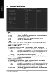
... HDD Auto-Detection Press "Enter" to select this to set the access mode for automatic device detection. The four options are : Large/Auto(default:Auto) GA-M57SLI-S4 Motherboard - 36 - Through Dec.
... HDD Auto-Detection Press "Enter" to select this to set the access mode for automatic device detection. The four options are : Large/Auto(default:Auto) GA-M57SLI-S4 Motherboard - 36 - Through Dec.


