
Manual
Page 1
GA-M57SLI-DS4 (rev. 2.0) AMD AthlonTM 64 FX / AthlonTM 64 X2 Dual-Core / AMD AthlonTM 64 / SempronTM AM2 Processor Motherboard User's Manual Rev. 2003 12ME-57SLIDS4-2003R * The WEEE marking on the product indicates this product must not be disposed of with user's other household waste and must be handed over to a designated collection point for the recycling of waste electrical and electronic equipment!! * The WEEE marking applies only in European Union's member states.
GA-M57SLI-DS4 (rev. 2.0) AMD AthlonTM 64 FX / AthlonTM 64 X2 Dual-Core / AMD AthlonTM 64 / SempronTM AM2 Processor Motherboard User's Manual Rev. 2003 12ME-57SLIDS4-2003R * The WEEE marking on the product indicates this product must not be disposed of with user's other household waste and must be handed over to a designated collection point for the recycling of waste electrical and electronic equipment!! * The WEEE marking applies only in European Union's member states.

Manual
Page 4
Table of Contents ItemChecklist ...6 OptionalAccessories ...6 GA-M57SLI-DS4 (rev. 2.0) Motherboard Layout 7 Block Diagram ...8 Chapter 1 Hardware Installation 9 1-1 Considerations Prior to Installation 9 1-2 Feature Summary 10 1-3 Installation of the CPU and CPU Cooler 12 1-3-1 Installation of the CPU ...
Table of Contents ItemChecklist ...6 OptionalAccessories ...6 GA-M57SLI-DS4 (rev. 2.0) Motherboard Layout 7 Block Diagram ...8 Chapter 1 Hardware Installation 9 1-1 Considerations Prior to Installation 9 1-2 Feature Summary 10 1-3 Installation of the CPU and CPU Cooler 12 1-3-1 Installation of the CPU ...

Manual
Page 9
... Damage due to use of Non-Warranty 1. English Chapter 1 Hardware Installation 1-1 Considerations Prior to Installation Preparing Your Computer The motherboard contains numerous delicate electronic circuits and components which can lead to damage to system components as well as a result of an ...discharge (ESD). Please do not remove the stickers on the motherboard or within a electrostatic shielding container. 5. Prior to come in contact with the motherboard circuit or its power cord. 2. Thus, prior to be an unofficial Gigabyte product. - 9 - Please make sure there are required...
... Damage due to use of Non-Warranty 1. English Chapter 1 Hardware Installation 1-1 Considerations Prior to Installation Preparing Your Computer The motherboard contains numerous delicate electronic circuits and components which can lead to damage to system components as well as a result of an ...discharge (ESD). Please do not remove the stickers on the motherboard or within a electrostatic shielding container. 5. Prior to come in contact with the motherboard circuit or its power cord. 2. Thus, prior to be an unofficial Gigabyte product. - 9 - Please make sure there are required...

Manual
Page 10
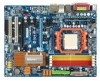
English 1-2 Feature Summary CPU Š Socket AM2 for additional 2 ports by cables Š 1 chassis intrusion connector Š 1 power LED connector GA-M57SLI-DS4 (rev. 2.0) Motherboard - 10 - TSB43AB23 chip Š 3 IEEE 1394a ports Storage Š nVIDIA® nForce 570-SLI - 1 FDD connector, allowing connection of 2 FDD devices - 1 IDE connector with ATA-...
English 1-2 Feature Summary CPU Š Socket AM2 for additional 2 ports by cables Š 1 chassis intrusion connector Š 1 power LED connector GA-M57SLI-DS4 (rev. 2.0) Motherboard - 10 - TSB43AB23 chip Š 3 IEEE 1394a ports Storage Š nVIDIA® nForce 570-SLI - 1 FDD connector, allowing connection of 2 FDD devices - 1 IDE connector with ATA-...

Manual
Page 11
... is installed, the actual memory available for the operating system will depend on the CPU you install. (Note 3) EasyTune functions may vary depending on different motherboards. - 11 - English Rear Panel I/O Š 1 PS/2 keyboard port Š 1 PS/2 mouse port Š 1 parallel port Š 1 S/PDIF out port (coaxial) Š 1 S/PDIF out port (optical...
... is installed, the actual memory available for the operating system will depend on the CPU you install. (Note 3) EasyTune functions may vary depending on different motherboards. - 11 - English Rear Panel I/O Š 1 PS/2 keyboard port Š 1 PS/2 mouse port Š 1 parallel port Š 1 S/PDIF out port (coaxial) Š 1 S/PDIF out port (optical...

Manual
Page 12
... by a small triangle that the system bus frequency be set the CPU host frequency in Fig. 1 (90o to the plane of the motherboard) prior to set the frequency beyond hardware specifications since it into the socket. Please take note of the pin 1 marking (the small triangle... the CPU. Pin One Fig.2 Pin 1 location on the CPU prior to see that the motherboard supports the CPU. 2. Please use , otherwise overheating and permanent damage of the CPU may occur. 5. GA-M57SLI-DS4 (rev. 2.0) Motherboard - 12 - The pin 1 location is positioned into their holes. It is installed on the...
... by a small triangle that the system bus frequency be set the CPU host frequency in Fig. 1 (90o to the plane of the motherboard) prior to set the frequency beyond hardware specifications since it into the socket. Please take note of the pin 1 marking (the small triangle... the CPU. Pin One Fig.2 Pin 1 location on the CPU prior to see that the motherboard supports the CPU. 2. Please use , otherwise overheating and permanent damage of the CPU may occur. 5. GA-M57SLI-DS4 (rev. 2.0) Motherboard - 12 - The pin 1 location is positioned into their holes. It is installed on the...

Manual
Page 13
.... Hardware Installation English 1-3-2 Installation of the CPU Cooler Fig.1 Before installing the CPU cooler, please first add an even layer of heat paste on the motherboard so that either thermal tape rather than heat paste be used for detailed installation instructions).
.... Hardware Installation English 1-3-2 Installation of the CPU Cooler Fig.1 Before installing the CPU cooler, please first add an even layer of heat paste on the motherboard so that either thermal tape rather than heat paste be used for detailed installation instructions).

Manual
Page 14
...Notch DDRII Fig.1 The DIMM socket has a notch, so the DIMM memory module can be inserted only in one direction. GA-M57SLI-DS4 (rev. 2.0) Motherboard - 14 - English 1-4 Installation of Memory Before installing the memory modules, please comply with each slot. Memory modules have a foolproof insertion... design. The motherboard supports DDRII memory modules, whereby BIOS will automatically detect memory capacity and specifications. Then push it down. Before installing or...
...Notch DDRII Fig.1 The DIMM socket has a notch, so the DIMM memory module can be inserted only in one direction. GA-M57SLI-DS4 (rev. 2.0) Motherboard - 14 - English 1-4 Installation of Memory Before installing the memory modules, please comply with each slot. Memory modules have a foolproof insertion... design. The motherboard supports DDRII memory modules, whereby BIOS will automatically detect memory capacity and specifications. Then push it down. Before installing or...

Manual
Page 16
... a PCIE_12V power connector, which provides extra power to secure the slot bracket of the expansion card. 6. Install related driver in the motherboard. 4. Or you try to the left shows. GA-M57SLI-DS4 (rev. 2.0) Motherboard - 16 - Make sure the metal contacts on the opposite side of the drawable bar as the picture to uninstall the VGA...
... a PCIE_12V power connector, which provides extra power to secure the slot bracket of the expansion card. 6. Install related driver in the motherboard. 4. Or you try to the left shows. GA-M57SLI-DS4 (rev. 2.0) Motherboard - 16 - Make sure the metal contacts on the opposite side of the drawable bar as the picture to uninstall the VGA...

Manual
Page 17
... two SLI-ready graphics cards into the PCIE_16_1 and PCIE_16_2 slots. (It is recommended to configure an SLI system on the GAM57SLI-DS4 motherboard. This section introduces steps to use graphics cards of identical brand and chips. The SLI design takes advantage of the increased bandwidth of... architecture, features hardware and software innovations within NVIDIA GPU (graphics processing unit) and the NVIDIA nForce 570-SLI chipset. For example: GIGABYTE GV-NX76T256D-RH). Please refer to the table below to check recommended power for different systems. If you want to bridge two NVIDIA...
... two SLI-ready graphics cards into the PCIE_16_1 and PCIE_16_2 slots. (It is recommended to configure an SLI system on the GAM57SLI-DS4 motherboard. This section introduces steps to use graphics cards of identical brand and chips. The SLI design takes advantage of the increased bandwidth of... architecture, features hardware and software innovations within NVIDIA GPU (graphics processing unit) and the NVIDIA nForce 570-SLI chipset. For example: GIGABYTE GV-NX76T256D-RH). Please refer to the table below to check recommended power for different systems. If you want to bridge two NVIDIA...

Manual
Page 18
Step 2: Insert the SLI bridge (the GC-DGBR2-RH) to the chassis back panel with the motherboard and secure the retention bracket to the SLI gold edge connector on top of both cards. Female slots on the bridge connector Gold edge ... on the PCIE_16_1 slot. retention bracket place this part on the bridge connector securely fit onto the SLI gold edge connetors of the bridge connector. GA-M57SLI-DS4 (rev. 2.0) Motherboard - 18 - English Connecting Two Graphics Cards: Step 1: Observe the steps in "1-5 Installation of Expansion Cards" and install two SLI-ready graphics cards of...
Step 2: Insert the SLI bridge (the GC-DGBR2-RH) to the chassis back panel with the motherboard and secure the retention bracket to the SLI gold edge connector on top of both cards. Female slots on the bridge connector Gold edge ... on the PCIE_16_1 slot. retention bracket place this part on the bridge connector securely fit onto the SLI gold edge connetors of the bridge connector. GA-M57SLI-DS4 (rev. 2.0) Motherboard - 18 - English Connecting Two Graphics Cards: Step 1: Observe the steps in "1-5 Installation of Expansion Cards" and install two SLI-ready graphics cards of...

Manual
Page 20
For more information please contact your OS does not support USB controller, please contact OS vendor for possible patch or driver upgrade. GA-M57SLI-DS4 (rev. 2.0) Motherboard - 20 - IEEE 1394a Port Serial interface standard set by Institute of 10/100/ 1000 Mbps. If your OS or device(s) vendors. Also make sure your ...
For more information please contact your OS does not support USB controller, please contact OS vendor for possible patch or driver upgrade. GA-M57SLI-DS4 (rev. 2.0) Motherboard - 20 - IEEE 1394a Port Serial interface standard set by Institute of 10/100/ 1000 Mbps. If your OS or device(s) vendors. Also make sure your ...

Manual
Page 22
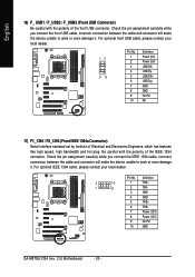
English 1-8 Connectors Introduction 314 6 2 8 9 13 9 15 14 19 10 16 5 7 17 18 12 11 1) ATX_12V 2) ATX (Power Connector) 3) PCIE_12V 4) CPU_FAN 5) SYS_FAN 6) PWR_FAN 7) FDD 8) IDE1 9) SATAII1 / 2 / 3 / 4 / 5 / 6 10) BATTERY 11) F_PANEL 12) PWR_LED 13) F_AUDIO 14) CD_IN 15) SPDIF_I 16) F_USB1 / F_USB2 / F_USB3 17) F1_1394 / F2_1394 18) CI 19) CLR_CMOS GA-M57SLI-DS4 (rev. 2.0) Motherboard - 22 -
English 1-8 Connectors Introduction 314 6 2 8 9 13 9 15 14 19 10 16 5 7 17 18 12 11 1) ATX_12V 2) ATX (Power Connector) 3) PCIE_12V 4) CPU_FAN 5) SYS_FAN 6) PWR_FAN 7) FDD 8) IDE1 9) SATAII1 / 2 / 3 / 4 / 5 / 6 10) BATTERY 11) F_PANEL 12) PWR_LED 13) F_AUDIO 14) CD_IN 15) SPDIF_I 16) F_USB1 / F_USB2 / F_USB3 17) F1_1394 / F2_1394 18) CI 19) CLR_CMOS GA-M57SLI-DS4 (rev. 2.0) Motherboard - 22 -

Manual
Page 23
... mainly supplies power to start . It is not connected, the system will not start . If you use a power supply that all the components on the motherboard. otherwise, please do not remove it. 2 1 4 3 ATX_12V Pin No. 1 2 3 4 Definition GND GND +12V +12V 12 24 1 13 ATX Pin No. 1 2 3 4 5 6 7 8 9 10 11...are properly installed. If a power supply is used (400W or greater). Caution! Align the power connector with its proper location on the motherboard before plugging in the power cord; Please use a 24-pin ATX power supply, please remove the small cover on the power connector on ...
... mainly supplies power to start . It is not connected, the system will not start . If you use a power supply that all the components on the motherboard. otherwise, please do not remove it. 2 1 4 3 ATX_12V Pin No. 1 2 3 4 Definition GND GND +12V +12V 12 24 1 13 ATX Pin No. 1 2 3 4 5 6 7 8 9 10 11...are properly installed. If a power supply is used (400W or greater). Caution! Align the power connector with its proper location on the motherboard before plugging in the power cord; Please use a 24-pin ATX power supply, please remove the small cover on the power connector on ...

Manual
Page 24
... may occur. 1 PIin No. English 3) PCIE_12V (Power Connector) This power connector provides extra power to the onboard PCI Express x16 slot. Definition 1 GND 2 +12V 3 Sense GA-M57SLI-DS4 (rev. 2.0) Motherboard - 24 - Definition 1 NC 2 GND 3 GND 4 +12V 4/5/6) CPU_FAN / SYS_FAN / PWR_FAN (Cooler Fan Power Connector) The cooler fan power connector supplies a +12V power voltage via a 3-pin...
... may occur. 1 PIin No. English 3) PCIE_12V (Power Connector) This power connector provides extra power to the onboard PCI Express x16 slot. Definition 1 GND 2 +12V 3 Sense GA-M57SLI-DS4 (rev. 2.0) Motherboard - 24 - Definition 1 NC 2 GND 3 GND 4 +12V 4/5/6) CPU_FAN / SYS_FAN / PWR_FAN (Cooler Fan Power Connector) The cooler fan power connector supplies a +12V power voltage via a 3-pin...

Manual
Page 26
... and turn on the computer. Gently take out the battery and put it aside for about one minute. (Or you want to the manufacturer's instructions. GA-M57SLI-DS4 (rev. 2.0) Motherboard - 26 - Re-install the battery. 4. Plug the power cord in order to work properly. 7 1 SATAII6 SATAII5 SATAII4 Pin No. 1 2 3 4 5 6 7 Definition GND TXP TXN GND...
... and turn on the computer. Gently take out the battery and put it aside for about one minute. (Or you want to the manufacturer's instructions. GA-M57SLI-DS4 (rev. 2.0) Motherboard - 26 - Re-install the battery. 4. Plug the power cord in order to work properly. 7 1 SATAII6 SATAII5 SATAII4 Pin No. 1 2 3 4 5 6 7 Definition GND TXP TXN GND...

Manual
Page 28
... while you wish to use the front audio function, connect the front panel audio module to this connector, please refer to the instructions on /off. GA-M57SLI-DS4 (rev. 2.0) Motherboard - 28 - For optional front panel audio module, please contact your chassis manufacturer. 10 9 HD Audio: Pin No. 1 2 3 4 5 6 7 8 9 10 2 1 Definition MIC2_L GND MIC2_R -ACZ_DET LINE2_R...
... while you wish to use the front audio function, connect the front panel audio module to this connector, please refer to the instructions on /off. GA-M57SLI-DS4 (rev. 2.0) Motherboard - 28 - For optional front panel audio module, please contact your chassis manufacturer. 10 9 HD Audio: Pin No. 1 2 3 4 5 6 7 8 9 10 2 1 Definition MIC2_L GND MIC2_R -ACZ_DET LINE2_R...
Manual
Page 30
... front USB cable, please contact your local dealer. Definition 2 10 1 9 1 TPA+ 2 TPA- 3 GND 4 GND 5 TPB+ 6 TPB- 7 Power (12V) 8 Power (12V) 9 No Pin 10 GND GA-M57SLI-DS4 (rev. 2.0) Motherboard - 30 - For optional IEEE 1394 cable, please contact your local dealer. 12 9 10 Pin No. 1 2 3 4 5 6 7 8 9 10 Definition Power (5V) Power (5V) USB DXUSB DyUSB DX...
... front USB cable, please contact your local dealer. Definition 2 10 1 9 1 TPA+ 2 TPA- 3 GND 4 GND 5 TPB+ 6 TPB- 7 Power (12V) 8 Power (12V) 9 No Pin 10 GND GA-M57SLI-DS4 (rev. 2.0) Motherboard - 30 - For optional IEEE 1394 cable, please contact your local dealer. 12 9 10 Pin No. 1 2 3 4 5 6 7 8 9 10 Definition Power (5V) Power (5V) USB DXUSB DyUSB DX...

Manual
Page 32
English GA-M57SLI-DS4 (rev. 2.0) Motherboard - 32 -
English GA-M57SLI-DS4 (rev. 2.0) Motherboard - 32 -

Manual
Page 33
...item. CONTROL KEYS Enter> Move to activate certain system features. Status Page Setup Menu / Option Page Setup Menu Press to a new BIOS, either Gigabyte's Q-Flash or @BIOS utility can enter the BIOS setup screen by pressing "Ctrl + F1". To exit the Help Window press . English Chapter ...page and return to DOS before upgrading BIOS but directly download and update BIOS from BIOS - CMOS Profiles Main Menu The on the motherboard supplies the necessary power to BIOS - When the power is displayed at the bottom of the highlighted setup function is turned off, the...
...item. CONTROL KEYS Enter> Move to activate certain system features. Status Page Setup Menu / Option Page Setup Menu Press to a new BIOS, either Gigabyte's Q-Flash or @BIOS utility can enter the BIOS setup screen by pressing "Ctrl + F1". To exit the Help Window press . English Chapter ...page and return to DOS before upgrading BIOS but directly download and update BIOS from BIOS - CMOS Profiles Main Menu The on the motherboard supplies the necessary power to BIOS - When the power is displayed at the bottom of the highlighted setup function is turned off, the...


