Manual
Page 1
GA-M55S-S3 (rev. 2.0) AMD Socket AM2 Processor Motherboard User's Manual Rev. 2002 12ME-M55S3R-2002R * The WEEE marking on the product indicates this product must not be disposed of with user's other household waste and must be handed over to a designated collection point for the recycling of waste electrical and electronic equipment!! * The WEEE marking applies only in European Union's member states.
GA-M55S-S3 (rev. 2.0) AMD Socket AM2 Processor Motherboard User's Manual Rev. 2002 12ME-M55S3R-2002R * The WEEE marking on the product indicates this product must not be disposed of with user's other household waste and must be handed over to a designated collection point for the recycling of waste electrical and electronic equipment!! * The WEEE marking applies only in European Union's member states.
Manual
Page 2
Motherboard GA-M55S-S3 (rev. 2.0) Nov. 10, 2006 Motherboard GA-M55S-S3 (rev. 2.0) Nov. 10, 2006
Motherboard GA-M55S-S3 (rev. 2.0) Nov. 10, 2006 Motherboard GA-M55S-S3 (rev. 2.0) Nov. 10, 2006
Manual
Page 4
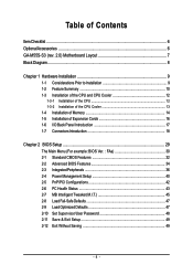
Table of Contents ItemChecklist ...6 OptionalAccessories ...6 GA-M55S-S3 (rev. 2.0) Motherboard Layout 7 Block Diagram ...8 Chapter 1 Hardware Installation 9 1-1 Considerations Prior to Installation 9 1-2 Feature Summary 10 1-3 Installation of the CPU and CPU Cooler 12 1-3-1 Installation of the CPU ...
Table of Contents ItemChecklist ...6 OptionalAccessories ...6 GA-M55S-S3 (rev. 2.0) Motherboard Layout 7 Block Diagram ...8 Chapter 1 Hardware Installation 9 1-1 Considerations Prior to Installation 9 1-2 Feature Summary 10 1-3 Installation of the CPU and CPU Cooler 12 1-3-1 Installation of the CPU ...
Manual
Page 7
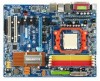
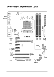
GA-M55S-S3 (rev. 2.0) Motherboard Layout CPU_FAN KB_MS ATX_12V ATX SPDIF_O SPDIFO_OPT Socket AM2 COMA LPT PWR_FAN USB 1394 USB LAN1 Marvell 88E1116 AUDIO PCIE_12V F_AUDIO PCIE_1 CODEC PCIE_16_1 PCIE_2 SPDIF_I CD_IN PCIE_3 PCIE_4 PCI1 IT8716 PCI2 REV: 2.0 FDD DDRII_1 DDRII_2 DDRII_3 DDRII_4 GA-M55S-S3 IDE1 SATAII4 SATAII1 SATAII2 SATAII3 BIOS nVIDIA® nForce 550 CLR_CMOS TSB43AB23 BATTERY F_USB3 F_USB2 F_USB1 F1_1394 F2_1394 CI F_PANEL PWR_LED SYS_FAN - 7 -
GA-M55S-S3 (rev. 2.0) Motherboard Layout CPU_FAN KB_MS ATX_12V ATX SPDIF_O SPDIFO_OPT Socket AM2 COMA LPT PWR_FAN USB 1394 USB LAN1 Marvell 88E1116 AUDIO PCIE_12V F_AUDIO PCIE_1 CODEC PCIE_16_1 PCIE_2 SPDIF_I CD_IN PCIE_3 PCIE_4 PCI1 IT8716 PCI2 REV: 2.0 FDD DDRII_1 DDRII_2 DDRII_3 DDRII_4 GA-M55S-S3 IDE1 SATAII4 SATAII1 SATAII2 SATAII3 BIOS nVIDIA® nForce 550 CLR_CMOS TSB43AB23 BATTERY F_USB3 F_USB2 F_USB1 F1_1394 F2_1394 CI F_PANEL PWR_LED SYS_FAN - 7 -

Manual
Page 9
... uneven surface. 7. Damage due to be an unofficial Gigabyte product. - 9 - Instances of electrostatic discharge (ESD). Hardware Installation It is switched off the computer and unplug its components. 5. Please do not allow screws to the motherboard, please do not place the computer system on the motherboard or within a electrostatic shielding container. 5. Product determined to...
... uneven surface. 7. Damage due to be an unofficial Gigabyte product. - 9 - Instances of electrostatic discharge (ESD). Hardware Installation It is switched off the computer and unplug its components. 5. Please do not allow screws to the motherboard, please do not place the computer system on the motherboard or within a electrostatic shielding container. 5. Product determined to...
Manual
Page 10
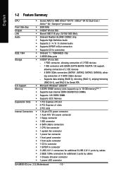
...; 1 CD In connector Š 1 S/PDIF In connector Š 3 USB 2.0/1.1 connectors for additional 6 USB 2.0/1.1 ports by cables Š 1 Chassis Intrusion connector Š 1 power LED connector GA-M55S-S3 (rev. 2.0) Motherboard - 10 - ing connection of 2 IDE devices - 4 SATA 3Gb/s connectors (SATAII1, SATAII2, SATAII3, SATAII4), allow- English 1-2 Feature Summary CPU Š Socket AM2 for additional 2 ports by...
...; 1 CD In connector Š 1 S/PDIF In connector Š 3 USB 2.0/1.1 connectors for additional 6 USB 2.0/1.1 ports by cables Š 1 Chassis Intrusion connector Š 1 power LED connector GA-M55S-S3 (rev. 2.0) Motherboard - 10 - ing connection of 2 IDE devices - 4 SATA 3Gb/s connectors (SATAII1, SATAII2, SATAII3, SATAII4), allow- English 1-2 Feature Summary CPU Š Socket AM2 for additional 2 ports by...
Manual
Page 11
... is installed, the actual memory available for the operating system will depend on the CPU you install. (Note 3) EasyTune functions may vary depending on different motherboards. - 11 - Hardware Installation English Rear Panel I/O Š 1 PS/2 keyboard port Š 1 PS/2 mouse port Š 1 parallel port Š 1 S/PDIF out port (coaxial) Š 1 S/PDIF out...
... is installed, the actual memory available for the operating system will depend on the CPU you install. (Note 3) EasyTune functions may vary depending on different motherboards. - 11 - Hardware Installation English Rear Panel I/O Š 1 PS/2 keyboard port Š 1 PS/2 mouse port Š 1 parallel port Š 1 S/PDIF out port (coaxial) Š 1 S/PDIF out...
Manual
Page 12
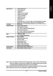
... the CPU. English 1-3 Installation of heat paste between the CPU and CPU cooler. 4. If this occurs, please change the positioning of the motherboard) prior to see that corresponds to set the CPU host frequency in Fig. 1 (90o to the socket and gently lower it does not ...otherwise overheating and permanent damage of the CPU. 3. If you install the CPU in Fig. 2. Pin One Fig.2 Pin 1 location on the CPU. GA-M55S-S3 (rev. 2.0) Motherboard - 12 - Gently place the CPU into its socket, place one finger down on the middle of the pin 1 marking (the small triangle) on ...
... the CPU. English 1-3 Installation of heat paste between the CPU and CPU cooler. 4. If this occurs, please change the positioning of the motherboard) prior to see that corresponds to set the CPU host frequency in Fig. 1 (90o to the socket and gently lower it does not ...otherwise overheating and permanent damage of the CPU. 3. If you install the CPU in Fig. 2. Pin One Fig.2 Pin 1 location on the CPU. GA-M55S-S3 (rev. 2.0) Motherboard - 12 - Gently place the CPU into its socket, place one finger down on the middle of the pin 1 marking (the small triangle) on ...

Manual
Page 13
... cooler. - 13 - English 1-3-2 Installation of the CPU Cooler Fig.1 Before installing the CPU cooler, please first add an even layer of heat paste on the motherboard so that either thermal tape rather than heat paste be used for detailed installation instructions). Hardware Installation The CPU cooler may adhere to the CPU...
... cooler. - 13 - English 1-3-2 Installation of the CPU Cooler Fig.1 Before installing the CPU cooler, please first add an even layer of heat paste on the motherboard so that either thermal tape rather than heat paste be used for detailed installation instructions). Hardware Installation The CPU cooler may adhere to the CPU...

Manual
Page 14
... clip at both edges of the DIMM sockets to insert the module, please switch the direction. Memory modules have a foolproof insertion design. GA-M55S-S3 (rev. 2.0) Motherboard - 14 - It is switched off to remove the DIMM module. Before installing or removing memory modules, please make sure that the memory...Please make sure that the computer power is recommended that they can be inserted only in only one direction. The motherboard supports DDRII memory modules, whereby BIOS will automatically detect memory capacity and specifications. The memory capacity used is supported by the...
... clip at both edges of the DIMM sockets to insert the module, please switch the direction. Memory modules have a foolproof insertion design. GA-M55S-S3 (rev. 2.0) Motherboard - 14 - It is switched off to remove the DIMM module. Before installing or removing memory modules, please make sure that the memory...Please make sure that the computer power is recommended that they can be inserted only in only one direction. The motherboard supports DDRII memory modules, whereby BIOS will automatically detect memory capacity and specifications. The memory capacity used is supported by the...
Manual
Page 16
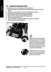
...sure the metal contacts on the back of the expansion card. 6. Replace your computer's chassis cover, screws and slot bracket from the computer. 3. GA-M55S-S3 (rev. 2.0) Motherboard - 16 - Remove your computer's chassis cover. 7. Press the expansion card firmly into the computer. 2. Install related driver from BIOS. 8. Make ...picture to the left shows. English 1-5 Installation of Expansion Cards You can also press the latch on the card are indeed seated in motherboard. 4. To install a VGA card or to install/ uninstall the VGA card. Please align the VGA card to the onboard PCI ...
...sure the metal contacts on the back of the expansion card. 6. Replace your computer's chassis cover, screws and slot bracket from the computer. 3. GA-M55S-S3 (rev. 2.0) Motherboard - 16 - Remove your computer's chassis cover. 7. Press the expansion card firmly into the computer. 2. Install related driver from BIOS. 8. Make ...picture to the left shows. English 1-5 Installation of Expansion Cards You can also press the latch on the card are indeed seated in motherboard. 4. To install a VGA card or to install/ uninstall the VGA card. Please align the VGA card to the onboard PCI ...
Manual
Page 18
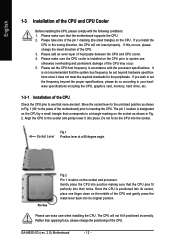
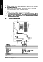
... for detailed software configuration information. 1-7 Connectors Introduction 3 14 6 2 8 13 15 14 7 1) ATX_12V 2) ATX (Power Connector) 3) PCIE_12V 4) CPU_FAN 5) SYS_FAN 6) PWR_FAN 7) FDD 8) IDE1 9) SATAII1 / 2 / 3 / 4 10) BATTERY GA-M55S-S3 (rev. 2.0) Motherboard 9 9 19 10 5 17 1812 11 16 11) F_PANEL 12) PWR_LED 13) F_AUDIO 14) CD_IN 15) SPDIF_I 16) F_USB1 / F_USB2 / F_USB3 17) F1_1394 / F2_1394 18) CI...
... for detailed software configuration information. 1-7 Connectors Introduction 3 14 6 2 8 13 15 14 7 1) ATX_12V 2) ATX (Power Connector) 3) PCIE_12V 4) CPU_FAN 5) SYS_FAN 6) PWR_FAN 7) FDD 8) IDE1 9) SATAII1 / 2 / 3 / 4 10) BATTERY GA-M55S-S3 (rev. 2.0) Motherboard 9 9 19 10 5 17 1812 11 16 11) F_PANEL 12) PWR_LED 13) F_AUDIO 14) CD_IN 15) SPDIF_I 16) F_USB1 / F_USB2 / F_USB3 17) F1_1394 / F2_1394 18) CI...
Manual
Page 19
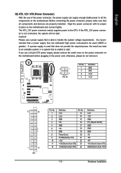
... please make sure that is used (400W or greater). Align the power connector with its proper location on the motherboard. Caution! Please use a 24-pin ATX power supply, please remove the small cover on the power connector on the... motherboard before plugging in the power cord; If a power supply is able to handle the system voltage requirements. If ...is not connected, the system will not start . If you use a power supply that all the components on the motherboard and connect tightly.
... please make sure that is used (400W or greater). Align the power connector with its proper location on the motherboard. Caution! Please use a 24-pin ATX power supply, please remove the small cover on the power connector on the... motherboard before plugging in the power cord; If a power supply is able to handle the system voltage requirements. If ...is not connected, the system will not start . If you use a power supply that all the components on the motherboard and connect tightly.
Manual
Page 20
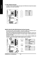
... Control Sense Speed Control SYS_FAN / PWR_FAN : Pin No. A red power connector wire indicates a positive connection and requires a +12V power voltage. Definition 1 GND 2 +12V 3 Sense GA-M55S-S3 (rev. 2.0) Motherboard - 20 - The black connector wire is the ground wire (GND). Most coolers are designed with color-coded power connector wires. Connect this connector depending on...
... Control Sense Speed Control SYS_FAN / PWR_FAN : Pin No. A red power connector wire indicates a positive connection and requires a +12V power voltage. Definition 1 GND 2 +12V 3 Sense GA-M55S-S3 (rev. 2.0) Motherboard - 20 - The black connector wire is the ground wire (GND). Most coolers are designed with color-coded power connector wires. Connect this connector depending on...
Manual
Page 22
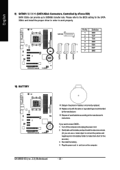
... 300MB/s transfer rate. Re-install the battery. 4. If you can provide up to the manufacturer's instructions. Turn off the computer and unplug the power cord. 2. GA-M55S-S3 (rev. 2.0) Motherboard - 22 - Dispose of explosion if battery is incorrectly replaced. SATAII4 Pin No. English SATAII1 SATAII2 SATAII3 9) SATAII1 / 2 / 3 / 4 (SATA 3Gb/s Connectors, Controlled by the manufacturer...
... 300MB/s transfer rate. Re-install the battery. 4. If you can provide up to the manufacturer's instructions. Turn off the computer and unplug the power cord. 2. GA-M55S-S3 (rev. 2.0) Motherboard - 22 - Dispose of explosion if battery is incorrectly replaced. SATAII4 Pin No. English SATAII1 SATAII2 SATAII3 9) SATAII1 / 2 / 3 / 4 (SATA 3Gb/s Connectors, Controlled by the manufacturer...
Manual
Page 24
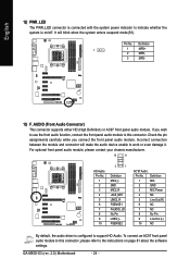
... module and connector will blink when the system enters suspend mode(S1). To connect an AC97 front panel audio module to this connector. Pin No. GA-M55S-S3 (rev. 2.0) Motherboard - 24 - If you connect the front panel audio module. Check the pin assignments carefully while you wish to use the front audio function, connect...
... module and connector will blink when the system enters suspend mode(S1). To connect an AC97 front panel audio module to this connector. Pin No. GA-M55S-S3 (rev. 2.0) Motherboard - 24 - If you connect the front panel audio module. Check the pin assignments carefully while you wish to use the front audio function, connect...
Manual
Page 26
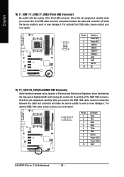
... has features like high speed, highbandwidth and hot plug. Definition 2 10 1 9 1 TPA+ 2 TPA- 3 GND 4 GND 5 TPB+ 6 TPB- 7 No Pin 7 Power (12V) 8 Power (12V) 10 GND GA-M55S-S3 (rev. 2.0) Motherboard - 26 -
... has features like high speed, highbandwidth and hot plug. Definition 2 10 1 9 1 TPA+ 2 TPA- 3 GND 4 GND 5 TPB+ 6 TPB- 7 No Pin 7 Power (12V) 8 Power (12V) 10 GND GA-M55S-S3 (rev. 2.0) Motherboard - 26 -
Manual
Page 28
English GA-M55S-S3 (rev. 2.0) Motherboard - 28 -
English GA-M55S-S3 (rev. 2.0) Motherboard - 28 -
Manual
Page 29
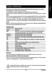
... default CMOS value from BIOS - CMOS Profiles Main Menu The on-line description of the highlighted setup function is displayed at the bottom of the motherboard. BIOS Setup English Chapter 2 BIOS Setup BIOS (Basic Input and Output System) includes a CMOS SETUP utility which allows user to configure required settings...do it with caution and avoid inadequate operation that does not require users to boot to the CMOS SRAM. If you to a new BIOS, either Gigabyte's Q-Flash or @BIOS utility can enter the BIOS setup screen by pressing "Ctrl + F1". To exit the Help Window press . Quit and not...
... default CMOS value from BIOS - CMOS Profiles Main Menu The on-line description of the highlighted setup function is displayed at the bottom of the motherboard. BIOS Setup English Chapter 2 BIOS Setup BIOS (Basic Input and Output System) includes a CMOS SETUP utility which allows user to configure required settings...do it with caution and avoid inadequate operation that does not require users to boot to the CMOS SRAM. If you to a new BIOS, either Gigabyte's Q-Flash or @BIOS utility can enter the BIOS setup screen by pressing "Ctrl + F1". To exit the Help Window press . Quit and not...
Manual
Page 30
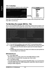
M55S-S3 FAa . . . . :BIOS Setup/Q-Flash, : XpressRecovery2, : Boot Menu 09/28/2006-NV-MCP55S-6A61JG07C.... The BIOS Setup menus described in the BIOS Setup when somehow the system is not stable as a profile. GA-M55S-S3 (rev. 2.0) Motherboard - 30 - Award Modular BIOS v6.00PG, An Energy Star Ally Copyright (C) 1984-2006, Award Software, Inc. ...F12 : Load CMOS from BIOS If your motherboard. This action makes the system reset to the default settings for your system becomes unstable and you load the ...
M55S-S3 FAa . . . . :BIOS Setup/Q-Flash, : XpressRecovery2, : Boot Menu 09/28/2006-NV-MCP55S-6A61JG07C.... The BIOS Setup menus described in the BIOS Setup when somehow the system is not stable as a profile. GA-M55S-S3 (rev. 2.0) Motherboard - 30 - Award Modular BIOS v6.00PG, An Energy Star Ally Copyright (C) 1984-2006, Award Software, Inc. ...F12 : Load CMOS from BIOS If your motherboard. This action makes the system reset to the default settings for your system becomes unstable and you load the ...


