
Manual
Page 3
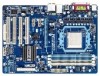
...in this manual are legally registered to the specifications and features in the use of this manual may be made by GIGABYTE without GIGABYTE's prior written permission. Disclaimer Information in any means without prior notice. Changes to their respective owners. For product-...related information, check on our website at: http://www.gigabyte.com Identifying Your Motherboard Revision The revision number on your motherboard revision before updating motherboard BIOS, drivers, or when looking for technical information. Check your motherboard looks like this...
...in this manual are legally registered to the specifications and features in the use of this manual may be made by GIGABYTE without GIGABYTE's prior written permission. Disclaimer Information in any means without prior notice. Changes to their respective owners. For product-...related information, check on our website at: http://www.gigabyte.com Identifying Your Motherboard Revision The revision number on your motherboard revision before updating motherboard BIOS, drivers, or when looking for technical information. Check your motherboard looks like this...
Manual
Page 4
Table of Contents Box Contents...6 Optional Items...6 GA-M52LT-D3P Motherboard Layout 7 GA-M52LT-D3P Motherboard Block Diagram 8 Chapter 1 Hardware Installation 9 1-1 Installation Precautions 9 1-2 Product Specifications 10 1-3 Installing the CPU and CPU ... an Expansion Card 17 1-6 Back Panel Connectors 18 1-7 Internal Connectors 20 Chapter 2 BIOS Setup 29 2-1 Startup Screen 30 2-2 The Main Menu 31 2-3 MB Intelligent Tweaker(M.I.T 33 2-4 Standard CMOS Features 36 2-5 Advanced BIOS Features 38 2-6 Integrated Peripherals 40 2-7 Power Management Setup 42 2-8 PnP/PCI Configurations ...
Table of Contents Box Contents...6 Optional Items...6 GA-M52LT-D3P Motherboard Layout 7 GA-M52LT-D3P Motherboard Block Diagram 8 Chapter 1 Hardware Installation 9 1-1 Installation Precautions 9 1-2 Product Specifications 10 1-3 Installing the CPU and CPU ... an Expansion Card 17 1-6 Back Panel Connectors 18 1-7 Internal Connectors 20 Chapter 2 BIOS Setup 29 2-1 Startup Screen 30 2-2 The Main Menu 31 2-3 MB Intelligent Tweaker(M.I.T 33 2-4 Standard CMOS Features 36 2-5 Advanced BIOS Features 38 2-6 Integrated Peripherals 40 2-7 Power Management Setup 42 2-8 PnP/PCI Configurations ...

Manual
Page 5
... 52 3-4 Contact...53 3-5 System...53 3-6 Download Center 54 3-7 New Utilities...54 Chapter 4 Unique Features 55 4-1 Xpress Recovery2 55 4-2 BIOS Update Utilities 58 4-2-1 Updating the BIOS with the Q-Flash Utility 58 4-2-2 Updating the BIOS with the @BIOS Utility 61 4-3 EasyTune 6...62 4-4 Auto Green...63 Chapter 5 Appendix...65 5-1 Configuring SATA Hard Drive(s 65 5-1-1 Configuring the Onboard...
... 52 3-4 Contact...53 3-5 System...53 3-6 Download Center 54 3-7 New Utilities...54 Chapter 4 Unique Features 55 4-1 Xpress Recovery2 55 4-2 BIOS Update Utilities 58 4-2-1 Updating the BIOS with the Q-Flash Utility 58 4-2-2 Updating the BIOS with the @BIOS Utility 61 4-3 EasyTune 6...62 4-4 Auto Green...63 Chapter 5 Appendix...65 5-1 Configuring SATA Hard Drive(s 65 5-1-1 Configuring the Onboard...
Manual
Page 8
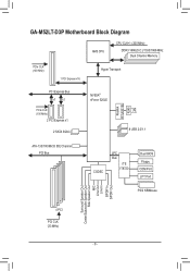
GA-M52LT-D3P Motherboard Block Diagram AM3 CPU CPU CLK+/- (200 MHz) DDR3 1666(O.C.)/1333/1066 MHz Dual Channel Memory PCIe CLK (100 MHz) 1 PCI Express x16 Hyper Transport PCI Express Bus x1 x1 PCIe CLK (100 MHz) 2 PCI Express x1 2 SATA 3Gb/s NVIDIA® nForce 520LE Realtek RTL8201EL RJ45 LAN 8 USB 2.0/1.1 ATA-133/100/66/33 IDE Channel PCI Bus CODEC LPC Bus iTE IT8720 Dual BIOS Floppy COM Port LPT Port PS/2 KB/Mouse Surround Speaker Out Center/Subwoofer Speaker Out Side Speaker Out MIC Line Out Line In S/PDIF In S/PDIF Out 4 PCI PCI CLK (33 MHz) - 8 -
GA-M52LT-D3P Motherboard Block Diagram AM3 CPU CPU CLK+/- (200 MHz) DDR3 1666(O.C.)/1333/1066 MHz Dual Channel Memory PCIe CLK (100 MHz) 1 PCI Express x16 Hyper Transport PCI Express Bus x1 x1 PCIe CLK (100 MHz) 2 PCI Express x1 2 SATA 3Gb/s NVIDIA® nForce 520LE Realtek RTL8201EL RJ45 LAN 8 USB 2.0/1.1 ATA-133/100/66/33 IDE Channel PCI Bus CODEC LPC Bus iTE IT8720 Dual BIOS Floppy COM Port LPT Port PS/2 KB/Mouse Surround Speaker Out Center/Subwoofer Speaker Out Side Speaker Out MIC Line Out Line In S/PDIF In S/PDIF Out 4 PCI PCI CLK (33 MHz) - 8 -

Manual
Page 11
...the CPU/system cooler you install. Hardware Installation BIOS ŠŠ 2 x 8 Mbit flash ŠŠ Use of licensed AWARD BIOS ŠŠ Support for DualBIOS™ ŠŠ PnP 1.0a, DMI 2.0, SM BIOS 2.4, ACPI 1.0b Unique Features ŠŠ Support for @BIOS ŠŠ Support for Q-Flash ŠŠ... ŠŠ Support for Microsoft® Windows 7/Vista/XP Form Factor ŠŠ ATX Form Factor; 30.5cm x 21.6cm * GIGABYTE reserves the right to make any changes to the product specifications and product-related information without prior notice. - 11 -
...the CPU/system cooler you install. Hardware Installation BIOS ŠŠ 2 x 8 Mbit flash ŠŠ Use of licensed AWARD BIOS ŠŠ Support for DualBIOS™ ŠŠ PnP 1.0a, DMI 2.0, SM BIOS 2.4, ACPI 1.0b Unique Features ŠŠ Support for @BIOS ŠŠ Support for Q-Flash ŠŠ... ŠŠ Support for Microsoft® Windows 7/Vista/XP Form Factor ŠŠ ATX Form Factor; 30.5cm x 21.6cm * GIGABYTE reserves the right to make any changes to the product specifications and product-related information without prior notice. - 11 -

Manual
Page 15
...Dual Channel Memory Configuration This motherboard provides four DDR3 memory sockets and supports Dual Channel Technology. After the memory is installed, the BIOS will double the original memory bandwidth. DDR3_1 DDR3_2 DDR3_3 DDR3_4 Due to prevent hardware damage. • Memory modules have a foolproof ... supports the memory. Dual Channel mode cannot be installed in only one DDR3 memory module is recommended that you begin to GIGABYTE's website for optimum performance. - 15 - Enabling Dual Channel memory mode will automatically detect the specifications and capacity of the...
...Dual Channel Memory Configuration This motherboard provides four DDR3 memory sockets and supports Dual Channel Technology. After the memory is installed, the BIOS will double the original memory bandwidth. DDR3_1 DDR3_2 DDR3_3 DDR3_4 Due to prevent hardware damage. • Memory modules have a foolproof ... supports the memory. Dual Channel mode cannot be installed in only one DDR3 memory module is recommended that you begin to GIGABYTE's website for optimum performance. - 15 - Enabling Dual Channel memory mode will automatically detect the specifications and capacity of the...
Manual
Page 17
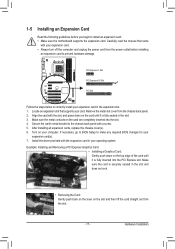
... to prevent hardware damage. Hardware Installation PCI Express x1 Slot PCI Express x16 Slot PCI Slot Follow the steps below to make any required BIOS changes for your expansion card in the slot and does not rock. • Removing the Card: Gently push back on the lever on... Locate an expansion slot that came with a screw. 5. Turn on the card are completely inserted into the PCI Express slot. If necessary, go to BIOS Setup to correctly install your expansion card(s). 7. Make sure the card is fully inserted into the slot. 4. Carefully read the manual that supports your expansion...
... to prevent hardware damage. Hardware Installation PCI Express x1 Slot PCI Express x16 Slot PCI Slot Follow the steps below to make any required BIOS changes for your expansion card in the slot and does not rock. • Removing the Card: Gently push back on the lever on... Locate an expansion slot that came with a screw. 5. Turn on the card are completely inserted into the PCI Express slot. If necessary, go to BIOS Setup to correctly install your expansion card(s). 7. Make sure the card is fully inserted into the slot. 4. Carefully read the manual that supports your expansion...

Manual
Page 24
... speaker and etc. If a problem is in S3/S4 sleep S3/S4/S5 Off state or powered off when the system is detected, the BIOS may differ by issuing a beep code. Hardware Installation - 24 - Note the positive and negative pins before connecting the cables. The LED keeps ... Green): Connects to the hard drive activity LED on the chassis front panel. When connecting your system using the power switch (refer to Chapter 2, "BIOS Setup," "Power Management Setup," for information about beep codes. • HD (Hard Drive Activity LED, Blue) Connects to the reset switch on the...
... speaker and etc. If a problem is in S3/S4 sleep S3/S4/S5 Off state or powered off when the system is detected, the BIOS may differ by issuing a beep code. Hardware Installation - 24 - Note the positive and negative pins before connecting the cables. The LED keeps ... Green): Connects to the hard drive activity LED on the chassis front panel. When connecting your system using the power switch (refer to Chapter 2, "BIOS Setup," "Power Management Setup," for information about beep codes. • HD (Hard Drive Activity LED, Blue) Connects to the reset switch on the...
Manual
Page 27
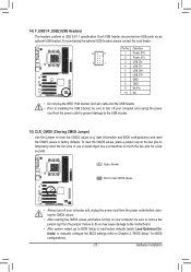
... a jumper cap on your computer, be sure to touch the two pins for BIOS configurations). - 27 - Failure to do so may cause damage to the motherboard. • After system restart, go to BIOS Setup to load factory defaults (select Load Optimized Defaults) or manually configure the... BIOS settings (refer to factory defaults. Each USB header can provide two USB ports via an optional USB bracket...
... a jumper cap on your computer, be sure to touch the two pins for BIOS configurations). - 27 - Failure to do so may cause damage to the motherboard. • After system restart, go to BIOS Setup to load factory defaults (select Load Optimized Defaults) or manually configure the... BIOS settings (refer to factory defaults. Each USB header can provide two USB ports via an optional USB bracket...

Manual
Page 28
Replace the battery. 4. 16) BAT (Battery) The battery provides power to keep the values (such as BIOS configurations, date, and time information) in the CMOS when the computer is replaced with an incorrect model. • Contact the place of purchase or local ...
Replace the battery. 4. 16) BAT (Battery) The battery provides power to keep the values (such as BIOS configurations, date, and time information) in the CMOS when the computer is replaced with an incorrect model. • Contact the place of purchase or local ...

Manual
Page 29
...-based utility that you not alter the default settings (unless you not flash the BIOS. Its major functions include conducting the Power-On Self-Test (POST) during the POST. To upgrade the BIOS, use either the GIGABYTE Q-Flash or @BIOS utility. • Q-Flash allows the user to clear the CMOS values.) - 29 - Refer to...
...-based utility that you not alter the default settings (unless you not flash the BIOS. Its major functions include conducting the Power-On Self-Test (POST) during the POST. To upgrade the BIOS, use either the GIGABYTE Q-Flash or @BIOS utility. • Q-Flash allows the user to clear the CMOS values.) - 29 - Refer to...
Manual
Page 30
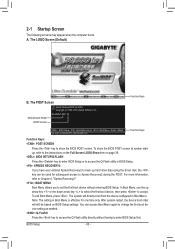
...RECOVERY2 If you to set the first boot device without having to accept. To show the BIOS POST screen. You can be used for one time only. Motherboard Model BIOS Version GA-M52LT-D3P D1 . . . . : BIOS Setup : XpressRecovery2 : Boot Menu : Qflash 12/14/2010-NV-MCP61-6A61KG0RC-00 Function Keys... Function Keys Function Keys: : POST SCREEN Press the key to show the BIOS POST screen at system startup, refer ...
...RECOVERY2 If you to set the first boot device without having to accept. To show the BIOS POST screen. You can be used for one time only. Motherboard Model BIOS Version GA-M52LT-D3P D1 . . . . : BIOS Setup : XpressRecovery2 : Boot Menu : Qflash 12/14/2010-NV-MCP61-6A61KG0RC-00 Function Keys... Function Keys Function Keys: : POST SCREEN Press the key to show the BIOS POST screen at system startup, refer ...

Manual
Page 31
... Supervisor Password Set User Password Save & Exit Setup Exit Without Saving ESC: Quit F8: Q-Flash Select Item F10: Save & Exit Setup Change CPU's Clock & Voltage BIOS Setup Program Function Keys Move the selection bar to select an item Execute command or enter the submenu Main Menu: Exit the... Help While in the Item Help block on the bottom line of the submenu. • If you do not find the settings you enter the BIOS Setup program, the Main Menu (as usual, select the Load Optimized Defaults item to set your system to display a help screen. Press to exit the...
... Supervisor Password Set User Password Save & Exit Setup Exit Without Saving ESC: Quit F8: Q-Flash Select Item F10: Save & Exit Setup Change CPU's Clock & Voltage BIOS Setup Program Function Keys Move the selection bar to select an item Execute command or enter the submenu Main Menu: Exit the... Help While in the Item Help block on the bottom line of the submenu. • If you do not find the settings you enter the BIOS Setup program, the Main Menu (as usual, select the Load Optimized Defaults item to set your system to display a help screen. Press to exit the...

Manual
Page 32
...User Password Change, set , or disable password. A user password only allows you to restrict access to the system and BIOS Setup. It allows you to the confirmation message will exit BIOS Setup. (Pressing can also carry out this task.) Exit Without Saving Abandon all the power-saving functions. ...time and date, hard drive types, floppy disk drive types, and the type of errors that stop the system boot, etc. Advanced BIOS Features Use this menu to configure the device boot order, advanced features available on the CPU, and the primary display adapter. Integrated ...
...User Password Change, set , or disable password. A user password only allows you to restrict access to the system and BIOS Setup. It allows you to the confirmation message will exit BIOS Setup. (Pressing can also carry out this task.) Exit Without Saving Abandon all the power-saving functions. ...time and date, hard drive types, floppy disk drive types, and the type of errors that stop the system boot, etc. Advanced BIOS Features Use this menu to configure the device boot order, advanced features available on the CPU, and the primary display adapter. Integrated ...

Manual
Page 33
... alter the North Bridge controller frequency for the installed CPU. The adjustable range is dependent on the CPU being used . Auto lets BIOS automatically set the PCIe clock frequency. Manual allows the memory clock control item below to CPU, chipset, or memory and reduce the ...specifications. Set Memory Clock Determines whether to default values.) CPU Frequency(MHz) Allows you made is dependent on your overall system configurations. BIOS Setup If this occurs, clear the CMOS values and reset the board to manually set the CPU host frequency. The adjustable range is...
... alter the North Bridge controller frequency for the installed CPU. The adjustable range is dependent on the CPU being used . Auto lets BIOS automatically set the PCIe clock frequency. Manual allows the memory clock control item below to CPU, chipset, or memory and reduce the ...specifications. Set Memory Clock Determines whether to default values.) CPU Frequency(MHz) Allows you made is dependent on your overall system configurations. BIOS Setup If this occurs, clear the CMOS values and reset the board to manually set the CPU host frequency. The adjustable range is...

Manual
Page 34
... Sets Memory Clock to single dual-channel. Auto 5T Auto 110ns Auto -- Auto -- Ganged Sets memory control mode to X4.00. RAS to X8.00. BIOS Setup - 34 - X8.00 Sets Memory Clock to CAS R/W Delay Options are: Auto (default), 5T~12T. Unganged Sets memory control mode to two single-channel...
... Sets Memory Clock to single dual-channel. Auto 5T Auto 110ns Auto -- Auto -- Ganged Sets memory control mode to X4.00. RAS to X8.00. BIOS Setup - 34 - X8.00 Sets Memory Clock to CAS R/W Delay Options are: Auto (default), 5T~12T. Unganged Sets memory control mode to two single-channel...

Manual
Page 35
... are : Auto (default), 90ns, 110ns, 160ns, 300ns, 350ns. The adjustable range is from 0.1V to your CPU or reduce the useful life of the CPU. BIOS Setup Row Cycle Time Options are : Auto (default), 4T~7T. Note: Increasing memory voltage may result in damage to 0.7V. Auto sets the CPU Northbridge...
... are : Auto (default), 90ns, 110ns, 160ns, 300ns, 350ns. The adjustable range is from 0.1V to your CPU or reduce the useful life of the CPU. BIOS Setup Row Cycle Time Options are : Auto (default), 4T~7T. Note: Increasing memory voltage may result in damage to 0.7V. Auto sets the CPU Northbridge...

Manual
Page 36
... down arrow key to set this item to None so the system will skip the detection of the two methods below : • Auto Lets the BIOS automatically detect IDE/SATA devices during the POST for faster system startup. is week (read-only), month, date and year. IDE Channel 2, 3 Master... IDE Auto-Detection Press to autodetect the parameters of the two methods below : • Auto Lets the BIOS automatically detect IDE/SATA devices during the POST for faster system startup. Access Mode Sets the hard drive access mode...
... down arrow key to set this item to None so the system will skip the detection of the two methods below : • Auto Lets the BIOS automatically detect IDE/SATA devices during the POST for faster system startup. is week (read-only), month, date and year. IDE Channel 2, 3 Master... IDE Auto-Detection Press to autodetect the parameters of the two methods below : • Auto Lets the BIOS automatically detect IDE/SATA devices during the POST for faster system startup. Access Mode Sets the hard drive access mode...

Manual
Page 37
...determine whether the system will stop for an error during the POST. All Errors Whenever the BIOS detects a non-fatal error the system boot will stop . If you to None. Options are determined by the BIOS POST. All, But Keyboard The system boot will not stop for a keyboard error but... stop for all other errors. BIOS Setup Head Number of the currently installed hard drive. Base Memory Also called conventional memory. Cylinder Number of sectors. Sector Number of cylinders....
...determine whether the system will stop for an error during the POST. All Errors Whenever the BIOS detects a non-fatal error the system boot will stop . If you to None. Options are determined by the BIOS POST. All, But Keyboard The system boot will not stop for a keyboard error but... stop for all other errors. BIOS Setup Head Number of the currently installed hard drive. Base Memory Also called conventional memory. Cylinder Number of sectors. Sector Number of cylinders....

Manual
Page 38
... C1E Support (Note) Enables or disables the C1E CPU power-saving function in independent partitions. BIOS Setup - 38 - Capability Away Mode Full Screen LOGO Show Backup BIOS Image to run multiple operating systems and applications in system halt state. Auto Lets the...Quiet driver dynamically adjust the CPU clock and VID to manually enable/disable CPU Core 1/2/3/4/5. 2-5 Advanced BIOS Features CMOS Setup Utility-Copyright (C) 1984-2010 Award Software Advanced BIOS Features AMD C1E Support (Note) Virtualization AMD K8 Cool&Quiet control CPU Unlock (Note) CPU core...
... C1E Support (Note) Enables or disables the C1E CPU power-saving function in independent partitions. BIOS Setup - 38 - Capability Away Mode Full Screen LOGO Show Backup BIOS Image to run multiple operating systems and applications in system halt state. Auto Lets the...Quiet driver dynamically adjust the CPU clock and VID to manually enable/disable CPU Core 1/2/3/4/5. 2-5 Advanced BIOS Features CMOS Setup Utility-Copyright (C) 1984-2010 Award Software Advanced BIOS Features AMD C1E Support (Note) Virtualization AMD K8 Cool&Quiet control CPU Unlock (Note) CPU core...


