User Manual
Page 6
English Table of Content Read Me First 4 Chapter 1 Introduction 8 Features Summary 8 GA-K8VM800M Motherboard Layout 10 Block Diagram 11 Chapter 2 Hardware Installation Process 13 Step 1: Install the Central Processing Unit (CPU 14 Step 2: Install ...20 Chapter 3 BIOS Setup 35 The Main Menu (For example: BIOS Ver. : F6 36 Standard CMOS Features 38 Advanced BIOS Features 40 Integrated Peripherals 41 Power Management Setup 44 PnP/PCI Configurations 45 PC Health Status 46 Frequency/Voltage Control 47 Load Fail-Safe Defaults 48 Load Optimized Defaults 48 GA-K8VM800M Motherboard - ...
English Table of Content Read Me First 4 Chapter 1 Introduction 8 Features Summary 8 GA-K8VM800M Motherboard Layout 10 Block Diagram 11 Chapter 2 Hardware Installation Process 13 Step 1: Install the Central Processing Unit (CPU 14 Step 2: Install ...20 Chapter 3 BIOS Setup 35 The Main Menu (For example: BIOS Ver. : F6 36 Standard CMOS Features 38 Advanced BIOS Features 40 Integrated Peripherals 41 Power Management Setup 44 PnP/PCI Configurations 45 PC Health Status 46 Frequency/Voltage Control 47 Load Fail-Safe Defaults 48 Load Optimized Defaults 48 GA-K8VM800M Motherboard - ...

User Manual
Page 7
Table of Content English Set Supervisor/User Password 49 Save & Exit Setup 50 Exit Without Saving 50 Chapter 4 Technical Reference 53 @BIOS™ Introduction 53 Flash BIOS Method Introduction 54 2-/4-/6-Channel Audio Function Introduction 65 Jack-Sensing Introduction 71 Xpress Recovery Introduction 73 Serial ATA RAID BIOS Utility Introduction 76 Chapter 5 Appendix 83 - 7 -
Table of Content English Set Supervisor/User Password 49 Save & Exit Setup 50 Exit Without Saving 50 Chapter 4 Technical Reference 53 @BIOS™ Introduction 53 Flash BIOS Method Introduction 54 2-/4-/6-Channel Audio Function Introduction 65 Jack-Sensing Introduction 71 Xpress Recovery Introduction 73 Serial ATA RAID BIOS Utility Introduction 76 Chapter 5 Appendix 83 - 7 -

User Manual
Page 9
Introduction English Hardware Monitor BIOS Additional Features Overclocking Form Factor y CPU/System fan revolution detect y CPU temperature detect y System voltage detect y CPU/System fan fail warning y Licensed AWARD BIOS y Supports Q-Flash y Supports Thermal Shutdown function y Supports @BIOS y Supports EasyTune y Over Clock (CPU/DDR/AGP/PCI) by BIOS y Micro ATX size form factor 24.4cm x 24.4cm - 9 -
Introduction English Hardware Monitor BIOS Additional Features Overclocking Form Factor y CPU/System fan revolution detect y CPU temperature detect y System voltage detect y CPU/System fan fail warning y Licensed AWARD BIOS y Supports Q-Flash y Supports Thermal Shutdown function y Supports @BIOS y Supports EasyTune y Over Clock (CPU/DDR/AGP/PCI) by BIOS y Micro ATX size form factor 24.4cm x 24.4cm - 9 -

User Manual
Page 11
English Block Diagram AGP 4X/8X AGPCLK (66MHz) VGA Port 3 PCI LAN RJ45 RTL8100C AMD AlthlonTM 64 processor (K8) CPUCLK+/- (200MHz) H.T. Bus 800MHz VIA K8M800 DDR RAM 400/333/266/200MHz 33 MHz 14.318 MHz BIOS VIA VT8237 LPC BUS IT8705F IR Game Port Floppy LPT Port AC97 Link PCICLK (33MHz) 2 Serial ATA Audio 8 USB CODEC Ports ATA33/66/100/133 IDE Channels 24 MHz 33 MHz PS/2 KB/Mouse 2 COM Ports MIC LINE-IN LINE-OUT - 11 - Introduction
English Block Diagram AGP 4X/8X AGPCLK (66MHz) VGA Port 3 PCI LAN RJ45 RTL8100C AMD AlthlonTM 64 processor (K8) CPUCLK+/- (200MHz) H.T. Bus 800MHz VIA K8M800 DDR RAM 400/333/266/200MHz 33 MHz 14.318 MHz BIOS VIA VT8237 LPC BUS IT8705F IR Game Port Floppy LPT Port AC97 Link PCICLK (33MHz) 2 Serial ATA Audio 8 USB CODEC Ports ATA33/66/100/133 IDE Channels 24 MHz 33 MHz PS/2 KB/Mouse 2 COM Ports MIC LINE-IN LINE-OUT - 11 - Introduction
User Manual
Page 13
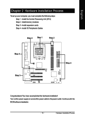
You have accomplished the hardware installation! Install memory modules Step 3 - Turn on the power supply or connect the power cable to the power outlet. Install I/O Peripherals Cables Step 4 Step 1 Step 2 Step 4 Step 3 Step 4 Congratulations! Continue with the BIOS/software installation. - 13 - Install the Central Processing Unit (CPU) Step 2 - Hardware Installation Process English Chapter 2 Hardware Installation Process To set up your computer, you must complete the following steps: Step 1 - Install expansion cards Step 4 -
You have accomplished the hardware installation! Install memory modules Step 3 - Turn on the power supply or connect the power cable to the power outlet. Install I/O Peripherals Cables Step 4 Step 1 Step 2 Step 4 Step 3 Step 4 Congratulations! Continue with the BIOS/software installation. - 13 - Install the Central Processing Unit (CPU) Step 2 - Hardware Installation Process English Chapter 2 Hardware Installation Process To set up your computer, you must complete the following steps: Step 1 - Install expansion cards Step 4 -

User Manual
Page 16
... size. Memory size can only fit in one direction due to the notch. Insert the DIMM memory module vertically into the DIMM socket. Notch DDR GA-K8VM800M Motherboard 1. The DIMM socket has a notch, so the DIMM memory module can only fit in one notch. Please note that the DIMM module can only... - The motherboard has 2 dual inline memory module (DIMM) sockets. Close the plastic clip at both edges of the DIMM sockets to the one direction. 2. The BIOS will cause improper installation. The DIMM module can vary between sockets.
... size. Memory size can only fit in one direction due to the notch. Insert the DIMM memory module vertically into the DIMM socket. Notch DDR GA-K8VM800M Motherboard 1. The DIMM socket has a notch, so the DIMM memory module can only fit in one notch. Please note that the DIMM module can only... - The motherboard has 2 dual inline memory module (DIMM) sockets. Close the plastic clip at both edges of the DIMM sockets to the one direction. 2. The BIOS will cause improper installation. The DIMM module can vary between sockets.

User Manual
Page 17
... of the expansion card. 6. Hardware Installation Process English Step 3: Install expansion cards 1. Be sure the metal contacts on the computer, if necessary, setup BIOS utility of expansion card from BIOS. 8. Press the expansion card firmly into the computer. 2. Please align the AGP card to install / uninstall the AGP card. Install related driver...
... of the expansion card. 6. Hardware Installation Process English Step 3: Install expansion cards 1. Be sure the metal contacts on the computer, if necessary, setup BIOS utility of expansion card from BIOS. 8. Press the expansion card firmly into the computer. 2. Please align the AGP card to install / uninstall the AGP card. Install related driver...
User Manual
Page 24
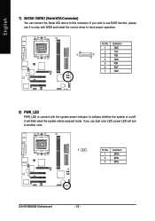
Definition 1 GND 2 TXP 1 7 3 TXN 4 GND 5 RXN 6 RXP 7 GND 8) PWR_LED PWR_LED is connect with BIOS and install the correct driver to have proper operation. Pin No. GA-K8VM800M Motherboard - 24 - If you wish to this connector. It will turn to indicate whether the system is on/off. If you use it in unity ...
Definition 1 GND 2 TXP 1 7 3 TXN 4 GND 5 RXN 6 RXP 7 GND 8) PWR_LED PWR_LED is connect with BIOS and install the correct driver to have proper operation. Pin No. GA-K8VM800M Motherboard - 24 - If you wish to this connector. It will turn to indicate whether the system is on/off. If you use it in unity ...
User Manual
Page 35
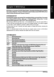
...to modify the basic system configuration. The program that does not require users to boot to DOS before upgrading BIOS but directly download and update BIOS from BIOS default table Load the Optimized Defaults Q-Flash utility System Information Save all the CMOS changes, only for the ... immediately will allow you require more advanced BIOS settings, please go to "Advanced BIOS" setting menu. Quit and not save the current BIOS to a disk in the event that you wish to upgrade to a new BIOS, either Gigabyte's Q-Flash or @BIOS utility can be reset to its original settings...
...to modify the basic system configuration. The program that does not require users to boot to DOS before upgrading BIOS but directly download and update BIOS from BIOS default table Load the Optimized Defaults Q-Flash utility System Information Save all the CMOS changes, only for the ... immediately will allow you require more advanced BIOS settings, please go to "Advanced BIOS" setting menu. Quit and not save the current BIOS to a disk in the event that you wish to upgrade to a new BIOS, either Gigabyte's Q-Flash or @BIOS utility can be reset to its original settings...

User Manual
Page 36
... function is displayed at the bottom of Award special enhanced features. GA-K8VM800M Motherboard - 36 - English Main Menu The on the screen. The BIOS Setup menus described in standard compatible BIOS. CMOS Setup Utility-Copyright (C) 1984-2005 Award Software ` Standard CMOS Features ` Advanced BIOS Features ` Integrated Peripherals ` Power Management Setup ` PnP/PCI Configurations ` PC Health...
... function is displayed at the bottom of Award special enhanced features. GA-K8VM800M Motherboard - 36 - English Main Menu The on the screen. The BIOS Setup menus described in standard compatible BIOS. CMOS Setup Utility-Copyright (C) 1984-2005 Award Software ` Standard CMOS Features ` Advanced BIOS Features ` Integrated Peripherals ` Power Management Setup ` PnP/PCI Configurations ` PC Health...

User Manual
Page 37
... CPU's clock and frequency ratio. z Load OptimizedDefaults Optimized Defaults indicates the value of PCI & PnP ISA resources. z Set User Password Change, set , or disable password. BIOS Setup z PnP/PCI Configurations This setup page includes all CMOS value changes and exit setup. - 37 - z Frequency/Voltage Control This setup page is the System...
... CPU's clock and frequency ratio. z Load OptimizedDefaults Optimized Defaults indicates the value of PCI & PnP ISA resources. z Set User Password Change, set , or disable password. BIOS Setup z PnP/PCI Configurations This setup page includes all CMOS value changes and exit setup. - 37 - z Frequency/Voltage Control This setup page is the System...

User Manual
Page 38
... through 2098 Time The times format in the month) < Ye a r > 1999 to Sat, determined by the BIOS and is calculated base on the 24-hour military-time clock. For example, 1 p.m. is , , , . GA-K8VM800M Motherboard - 38 - Week The week, from 1 to Sat. The time is displayed only Month The month, Jan...devices during POST. (Default value) None Select this option for the hard drive. You can use one of three methods: Auto Allows BIOS to select this if no IDE devices are used and the system will skip the automatic detection step and allow for faster system start ...
... through 2098 Time The times format in the month) < Ye a r > 1999 to Sat, determined by the BIOS and is calculated base on the 24-hour military-time clock. For example, 1 p.m. is , , , . GA-K8VM800M Motherboard - 38 - Week The week, from 1 to Sat. The time is displayed only Month The month, Jan...devices during POST. (Default value) None Select this option for the hard drive. You can use one of three methods: Auto Allows BIOS to select this if no IDE devices are used and the system will skip the automatic detection step and allow for faster system start ...

User Manual
Page 39
...Auto) Capacity Capacity of floppy disk drive A or drive B that used. - 39 - All Errors Whenever the BIOS detects a non-fatal error the system will determine the amount of the BIOS. All, But Disk/Key The system boot will be labeled on the motherboard. it will stop for all other... errors. (Default value) All, But Diskette The system boot will stop for a keyboard error; Extended Memory The BIOS determines how much extended memory is detected during the POST. Floppy 3 Mode Support (for all other errors. it will not stop for Japan Area...
...Auto) Capacity Capacity of floppy disk drive A or drive B that used. - 39 - All Errors Whenever the BIOS detects a non-fatal error the system will determine the amount of the BIOS. All, But Disk/Key The system boot will be labeled on the motherboard. it will stop for all other... errors. (Default value) All, But Diskette The system boot will stop for a keyboard error; Extended Memory The BIOS determines how much extended memory is detected during the POST. Floppy 3 Mode Support (for all other errors. it will not stop for Japan Area...

User Manual
Page 40
...move it down the list. Press to Setup will be denied if the correct password is not entered at the prompt. (Default value) GA-K8VM800M Motherboard - 40 - Password Check System Setup The system can not boot and can not access to move it up, or to Setup ...password is not entered at the prompt. USB-CDROM Select your boot device priority by USB-CDROM. English Advanced BIOS Features CMOS Setup Utility-Copyright (C) 1984-2005 Award Software Advanced BIOS Features ` Hard Disk Boot Priority First Boot Device Second Boot Device Third Boot Device Password Check [Press Enter]...
...move it down the list. Press to Setup will be denied if the correct password is not entered at the prompt. (Default value) GA-K8VM800M Motherboard - 40 - Password Check System Setup The system can not boot and can not access to move it up, or to Setup ...password is not entered at the prompt. USB-CDROM Select your boot device priority by USB-CDROM. English Advanced BIOS Features CMOS Setup Utility-Copyright (C) 1984-2005 Award Software Advanced BIOS Features ` Hard Disk Boot Priority First Boot Device Second Boot Device Third Boot Device Password Check [Press Enter]...
User Manual
Page 41
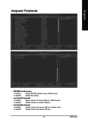
BIOS Setup On-Chip IDE Channel0 Enabled Enable onboard 1st channel IDE port. (Default value) Disabled Disable onboard 1st channel IDE port. On-Chip IDE Channel1 ...
BIOS Setup On-Chip IDE Channel0 Enabled Enable onboard 1st channel IDE port. (Default value) Disabled Disable onboard 1st channel IDE port. On-Chip IDE Channel1 ...

User Manual
Page 42
.... (Default value) Disabled Disable onboard LAN function. Onboard LAN Boot ROM This function decide whether to IDE. Disabled Disable this function. GA-K8VM800M Motherboard - 42 - USB 1.1 Controller Disable USB 1.1 host controller if you are not using high speed USB devices. USB 2.0 Controller...are not using USB devices. Enabled Enable USB 2.0 controller. (Default value) Disabled Disable USB 2.0 controller. Onboard Serial Port 1 Auto BIOS will automatically setup the port 1 address. 3F8/IRQ4 Enable onboard Serial port 1 and address is 3F8/IRQ4. (Default value) 2F8/IRQ3...
.... (Default value) Disabled Disable onboard LAN function. Onboard LAN Boot ROM This function decide whether to IDE. Disabled Disable this function. GA-K8VM800M Motherboard - 42 - USB 1.1 Controller Disable USB 1.1 host controller if you are not using high speed USB devices. USB 2.0 Controller...are not using USB devices. Enabled Enable USB 2.0 controller. (Default value) Disabled Disable USB 2.0 controller. Onboard Serial Port 1 Auto BIOS will automatically setup the port 1 address. 3F8/IRQ4 Enable onboard Serial port 1 and address is 3F8/IRQ4. (Default value) 2F8/IRQ3...

User Manual
Page 43
...Set Game Port Address to determine which infrared(IR) function of onboard I /O chip UART to IrDA Mode. English Onboard Serial Port 2 Auto BIOS will available when "UART Mode Select" doesn't set at Normal. Disabled Disable onboard LPT port. 3BC/IRQ7 Enable onboard LPT port and address... is 278/IRQ5. Half IR Function Duplex Half. (Default value) Full IR Function Duplex Full. BIOS Setup UART Mode Select This item allows you to 209. Disabled Disable this function. (Default value) Midi Port IRQ 5 Set Midi Port...
...Set Game Port Address to determine which infrared(IR) function of onboard I /O chip UART to IrDA Mode. English Onboard Serial Port 2 Auto BIOS will available when "UART Mode Select" doesn't set at Normal. Disabled Disable onboard LPT port. 3BC/IRQ7 Enable onboard LPT port and address... is 278/IRQ5. Half IR Function Duplex Half. (Default value) Full IR Function Duplex Full. BIOS Setup UART Mode Select This item allows you to 209. Disabled Disable this function. (Default value) Midi Port IRQ 5 Set Midi Port...

User Manual
Page 45
... IRQ 3,4,5,7,9,10,11,12,14,15 to PCI 2. Auto assign IRQ to PCI 2. (Default value) Set IRQ 3,4,5,7,9,10,11,12,14,15 to PCI 3. - 45 - BIOS Setup Enabled Enable Modem Ring on function. (Default value) Resume by Alarm You can awake the system from any suspend state. Date (of Month) Alarm...
... IRQ 3,4,5,7,9,10,11,12,14,15 to PCI 2. Auto assign IRQ to PCI 2. (Default value) Set IRQ 3,4,5,7,9,10,11,12,14,15 to PCI 3. - 45 - BIOS Setup Enabled Enable Modem Ring on function. (Default value) Resume by Alarm You can awake the system from any suspend state. Date (of Month) Alarm...
User Manual
Page 47
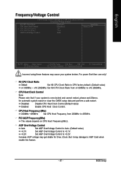
CPU Host Frequency (Mhz) 200MHz ~455MHz Set CPU Host Frequency from x4 800Mhz to AGP Card when enable this feature. - 47 - BIOS Setup English Frequency/Voltage Control CMOS Setup Utility-Copyright (C) 1984-2005 Award Software Frequency/Voltage Control K8 CPU Clock Ratio CPU Host Clock Control x CPU ...
CPU Host Frequency (Mhz) 200MHz ~455MHz Set CPU Host Frequency from x4 800Mhz to AGP Card when enable this feature. - 47 - BIOS Setup English Frequency/Voltage Control CMOS Setup Utility-Copyright (C) 1984-2005 Award Software Frequency/Voltage Control K8 CPU Clock Ratio CPU Host Clock Control x CPU ...

User Manual
Page 48
GA-K8VM800M Motherboard - 48 - Load Optimized Defaults CMOS Setup Utility-Copyright (C) 1984-2005 Award Software ` Standard CMOS Features ` Advanced BIOS Features ` Integrated Peripherals ` Power Management Setup ` PnP/PCI Configurations ` PC Health Status ` Frequency/Voltage Control ESC: Quit...Exit Without Saving KLJI: Select Item F10: Save & Exit Setup Load Optimized Defaults Selecting this field loads the factory defaults for BIOS and Chipset Features which the system automatically detects. English Load Fail-Safe Defaults CMOS Setup Utility-Copyright (C) 1984-2005 Award Software ...
GA-K8VM800M Motherboard - 48 - Load Optimized Defaults CMOS Setup Utility-Copyright (C) 1984-2005 Award Software ` Standard CMOS Features ` Advanced BIOS Features ` Integrated Peripherals ` Power Management Setup ` PnP/PCI Configurations ` PC Health Status ` Frequency/Voltage Control ESC: Quit...Exit Without Saving KLJI: Select Item F10: Save & Exit Setup Load Optimized Defaults Selecting this field loads the factory defaults for BIOS and Chipset Features which the system automatically detects. English Load Fail-Safe Defaults CMOS Setup Utility-Copyright (C) 1984-2005 Award Software ...


