User Manual
Page 4
... GA-K8NXP-SLI Motherboard Layout 6 Block Diagram ...7 Chapter 1 Hardware Installation 9 1-1 Considerations Prior to Installation 9 1-2 Feature Summary 10 1-3 Installation of the CPU and Fan Heat Sink 12 1-3-1 Installation of the CPU 12 1-3-2 Installation of the Fan Heat Sink 13 1-4 Installation of Memory ...14 1-5 Installation of Expansion Cards 16 1-6 Installation of K8DPS (Dual Power System 17 1-7 Setup of SLI (Scalable Link Interface) Configuration 18 1-8 I/O Back Panel Introduction 21 1-9 ...
... GA-K8NXP-SLI Motherboard Layout 6 Block Diagram ...7 Chapter 1 Hardware Installation 9 1-1 Considerations Prior to Installation 9 1-2 Feature Summary 10 1-3 Installation of the CPU and Fan Heat Sink 12 1-3-1 Installation of the CPU 12 1-3-2 Installation of the Fan Heat Sink 13 1-4 Installation of Memory ...14 1-5 Installation of Expansion Cards 16 1-6 Installation of K8DPS (Dual Power System 17 1-7 Setup of SLI (Scalable Link Interface) Configuration 18 1-8 I/O Back Panel Introduction 21 1-9 ...
User Manual
Page 10
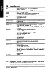
Line Out (Front Speaker Out) ; MIC ; GA-K8NXP-SLI Motherboard - 10 - Surround Speaker Out (Rear Speaker Out) ; For example, 4 GB of memory size will instead be shown as 3.xxGB memory during system startup. Center/Subwoofer Speaker Out ; Side Speaker Out connection Š SPDIF In/Out connection Š...; CD In connection Š IT8712F (Note) Due to 4GB memory) (Note) Š Supports dual channel DDR 400/333/266/200 DIMM Š 2 PCI Express x 16 slots Š 2 PCI Express x 1 ...
Line Out (Front Speaker Out) ; MIC ; GA-K8NXP-SLI Motherboard - 10 - Surround Speaker Out (Rear Speaker Out) ; For example, 4 GB of memory size will instead be shown as 3.xxGB memory during system startup. Center/Subwoofer Speaker Out ; Side Speaker Out connection Š SPDIF In/Out connection Š...; CD In connection Š IT8712F (Note) Due to 4GB memory) (Note) Š Supports dual channel DDR 400/333/266/200 DIMM Š 2 PCI Express x 16 slots Š 2 PCI Express x 1 ...
User Manual
Page 12
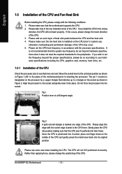
..., memory, hard drive, etc. 1-3-1 Installation of the CPU and gently press the metal lever back into its original position. Align the processor to inserting the processor. Once the CPU is installed on the CPU prior to a triangle on the middle of the CPU Check the processor pins to the CPU lever. GA-K8NXP-SLI...
..., memory, hard drive, etc. 1-3-1 Installation of the CPU and gently press the metal lever back into its original position. Align the processor to inserting the processor. Once the CPU is installed on the CPU prior to a triangle on the middle of the CPU Check the processor pins to the CPU lever. GA-K8NXP-SLI...
User Manual
Page 14
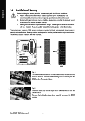
....1 The DIMM socket has a notch, so the DIMM memory module can be installed in one direction. Insert the DIMM memory module vertically into the DIMM socket. Memory modules have a foolproof insertion design. The memory capacity used is switched off to remove the DIMM module... the direction. A memory module can only fit in only one direction. The motherboard supports DDR memory modules, whereby BIOS will automatically detect memory capacity and specifications. Please make sure that the memory used can be used. 2. Then push it down. GA-K8NXP-SLI Motherboard - 14 -...
....1 The DIMM socket has a notch, so the DIMM memory module can be installed in one direction. Insert the DIMM memory module vertically into the DIMM socket. Memory modules have a foolproof insertion design. The memory capacity used is switched off to remove the DIMM module... the direction. A memory module can only fit in only one direction. The motherboard supports DDR memory modules, whereby BIOS will automatically detect memory capacity and specifications. Please make sure that the memory used can be used. 2. Then push it down. GA-K8NXP-SLI Motherboard - 14 -...

User Manual
Page 15
...operating the Dual Channel Technology, the bandwidth of Memory Bus will cause system unable to use memory modules of the memory configurations below for Dual Channel memory configuration. 1. To enable Dual Channel mode with 4 memory modules, it is recommended to use memory modules of the same color. 3. The following...be used to operate the Dual Channel Technology, please follow the guidelines below will double. English Dual Channel Memory Configuration The GA-K8NXP-SLI supports the Dual Channel Technology. Due to CPU limitation, if you want to achieve Dual Channel mode, we...
...operating the Dual Channel Technology, the bandwidth of Memory Bus will cause system unable to use memory modules of the memory configurations below for Dual Channel memory configuration. 1. To enable Dual Channel mode with 4 memory modules, it is recommended to use memory modules of the same color. 3. The following...be used to operate the Dual Channel Technology, please follow the guidelines below will double. English Dual Channel Memory Configuration The GA-K8NXP-SLI supports the Dual Channel Technology. Due to CPU limitation, if you want to achieve Dual Channel mode, we...
User Manual
Page 40
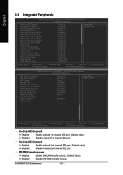
... Slave RAID Serial-ATA 1 SATA 1 Primary RAID SATA 1 Secondary RAID Serial-ATA 2 SATA 2 Primary RAID SATA 2 Secondary RAID IDE Prefetch Mode On-Chip USB USB Memory Type [Enabled] [Enabled] [Enabled] [Auto] [Disabled] [Enabled] [Disabled] [Disabled] [Disabled] [Disabled] [Enabled] [Enabled] [Enabled] [Enabled] [Enabled] [Enabled] [Enabled] [V1.1+V2.0] [SHADOW] Item Help Menu Level... IDE port. On-Chip IDE Channel1 Enabled Enable onboard 2nd channel IDE port. (Default value) Disabled Disable onboard 2nd channel IDE port. F1: General Help GA-K8NXP-SLI Motherboard - 40 -
... Slave RAID Serial-ATA 1 SATA 1 Primary RAID SATA 1 Secondary RAID Serial-ATA 2 SATA 2 Primary RAID SATA 2 Secondary RAID IDE Prefetch Mode On-Chip USB USB Memory Type [Enabled] [Enabled] [Enabled] [Auto] [Disabled] [Enabled] [Disabled] [Disabled] [Disabled] [Disabled] [Enabled] [Enabled] [Enabled] [Enabled] [Enabled] [Enabled] [Enabled] [V1.1+V2.0] [SHADOW] Item Help Menu Level... IDE port. On-Chip IDE Channel1 Enabled Enable onboard 2nd channel IDE port. (Default value) Disabled Disable onboard 2nd channel IDE port. F1: General Help GA-K8NXP-SLI Motherboard - 40 -

User Manual
Page 42
...port 1 and address is 3F8/IRQ4. (Default value) 2F8/IRQ3 3E8/IRQ4 Enable onboard Serial port 1 and address is 2E8/IRQ3. GA-K8NXP-SLI Motherboard - 42 - Enabled Enable onboard Serial ATA Chip.(Default value) Disabled Disable onboard Serial ATA Chip. Disable onboard Serial port 1. ...up a non-RAID configuration, please select JBOD mode from the RAID BIOS. USB Memory Type SHADOW Set USB Memory Type to SHADOW. (Default value) Base Memory (640K) Set USB Memory Type to Base Memory (640K). USB Keyboard Support Enabled Enable USB keyboard support. Disabled Disable USB keyboard ...
...port 1 and address is 3F8/IRQ4. (Default value) 2F8/IRQ3 3E8/IRQ4 Enable onboard Serial port 1 and address is 2E8/IRQ3. GA-K8NXP-SLI Motherboard - 42 - Enabled Enable onboard Serial ATA Chip.(Default value) Disabled Disable onboard Serial ATA Chip. Disable onboard Serial port 1. ...up a non-RAID configuration, please select JBOD mode from the RAID BIOS. USB Memory Type SHADOW Set USB Memory Type to SHADOW. (Default value) Base Memory (640K) Set USB Memory Type to Base Memory (640K). USB Keyboard Support Enabled Enable USB keyboard support. Disabled Disable USB keyboard ...
User Manual
Page 49
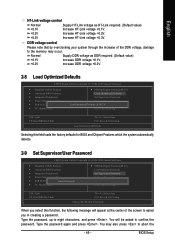
... voltage as HT-Link required. (Default value) Increase HT-Link voltage +0.1V. You will appear at the center of the DDR voltage, damage to the memory may also press to eight characters, and press . Increase HT-Link voltage +0.2V. Type the password, up to abort the - 49 - Type the password again...
... voltage as HT-Link required. (Default value) Increase HT-Link voltage +0.1V. You will appear at the center of the DDR voltage, damage to the memory may also press to eight characters, and press . Increase HT-Link voltage +0.2V. Type the password, up to abort the - 49 - Type the password again...
User Manual
Page 55
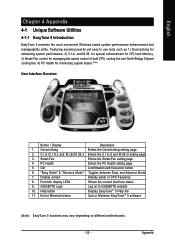
for special enhancement for CPU and Memory, 3) Smart-Fan control for managing fan speed control of CPU frequency 8. Display screen Display panel of both CPU cooling fan...Button / Display Description 1. C.I.A./C.I.A.2 and M.I.B./M.I.B.2 Enters the C.I.A./2 and M.I .B. Smart-Fan Enters the Smart-Fan setting page 4. GIGABYTE Logo Log on different motherboards. - 55 - Featuring several powerful yet easy to GIGABYTE website 10. Overclocking Enters the Overclocking setting page 2. Function display LEDs Shows the current functions status 9. Appendix and M.I .B./2 ...
for special enhancement for CPU and Memory, 3) Smart-Fan control for managing fan speed control of CPU frequency 8. Display screen Display panel of both CPU cooling fan...Button / Display Description 1. C.I.A./C.I.A.2 and M.I.B./M.I.B.2 Enters the C.I.A./2 and M.I .B. Smart-Fan Enters the Smart-Fan setting page 4. GIGABYTE Logo Log on different motherboards. - 55 - Featuring several powerful yet easy to GIGABYTE website 10. Overclocking Enters the Overclocking setting page 2. Function display LEDs Shows the current functions status 9. Appendix and M.I .B./2 ...
User Manual
Page 61
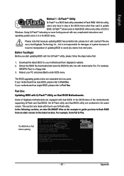
... are combined in DOS or Windows. In the following sections, we take GA-8KNXP Ultra as the example to Part Two. Part One: Updating BIOS with... System Health OK , VCore = 1.5250 Main Processor : Intel Pentium(R) 4 1.6GHz (133x12) Memory Testing : 131072K OK Memory Frequency 266 MHz in the BIOS menu when they want to a floppy disk. 3. In the BIOS...None Secondary Master : CREATIVEDVD-RM DVD1242E BC101 Secondary Slave : None Press DEL to avoid any claims from Gigabyte's website. 2. If your motherboard from end-users. Using Q-FlashTM indicating no more fooling around with ...
... are combined in DOS or Windows. In the following sections, we take GA-8KNXP Ultra as the example to Part Two. Part One: Updating BIOS with... System Health OK , VCore = 1.5250 Main Processor : Intel Pentium(R) 4 1.6GHz (133x12) Memory Testing : 131072K OK Memory Frequency 266 MHz in the BIOS menu when they want to a floppy disk. 3. In the BIOS...None Secondary Master : CREATIVEDVD-RM DVD1242E BC101 Secondary Slave : None Press DEL to avoid any claims from Gigabyte's website. 2. If your motherboard from end-users. Using Q-FlashTM indicating no more fooling around with ...
User Manual
Page 64
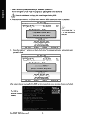
... Press Esc and then Y button to enter SETUP / Dual BIOS / Q-Flash / F9 For Xpress Recovery 09/23/2003-i875P-6A79BG03C-00 GA-K8NXP-SLI Motherboard - 64 - Dual BIOS Utility Boot From Main Bios Main ROM Type/Size SST 49LF003A Backup ROM Type/Size SST 49LF003A 512K 512K Wide...i875P AGPset BIOS for 8KNXP Ultra Fba Check System Health OK , VCore = 1.5250 Main Processor : Intel Pentium(R) 4 1.6GHz (133x12) Memory Testing : 131072K OK Memory Frequency 266 MHz in Single Channel Primary Master : FUJITSU MPE3170AT ED-03-08 Primary Slave : None Secondary Master : CREATIVEDVD-RM DVD1242E BC101 ...
... Press Esc and then Y button to enter SETUP / Dual BIOS / Q-Flash / F9 For Xpress Recovery 09/23/2003-i875P-6A79BG03C-00 GA-K8NXP-SLI Motherboard - 64 - Dual BIOS Utility Boot From Main Bios Main ROM Type/Size SST 49LF003A Backup ROM Type/Size SST 49LF003A 512K 512K Wide...i875P AGPset BIOS for 8KNXP Ultra Fba Check System Health OK , VCore = 1.5250 Main Processor : Intel Pentium(R) 4 1.6GHz (133x12) Memory Testing : 131072K OK Memory Frequency 266 MHz in Single Channel Primary Master : FUJITSU MPE3170AT ED-03-08 Primary Slave : None Secondary Master : CREATIVEDVD-RM DVD1242E BC101 ...

User Manual
Page 67
... then Y button to update BIOS. Intel 845GE AGPSet BIOS for 8GE800 F4 Check System Health OK Main Processor : Intel Pentium(R) 4 1.7GHz (100x17.0) Memory Testing : 122880K OK + 8192K Shared Memory Primary Master : FUJITSU MPE3170AT ED-03-08 Primary Slave : None Secondary Master : CREATIVEDVD-RM DVD1242E BC101 Secondary Slave : None Press DEL to Floppy...
... then Y button to update BIOS. Intel 845GE AGPSet BIOS for 8GE800 F4 Check System Health OK Main Processor : Intel Pentium(R) 4 1.7GHz (100x17.0) Memory Testing : 122880K OK + 8192K Shared Memory Primary Master : FUJITSU MPE3170AT ED-03-08 Primary Slave : None Secondary Master : CREATIVEDVD-RM DVD1242E BC101 Secondary Slave : None Press DEL to Floppy...
User Manual
Page 82
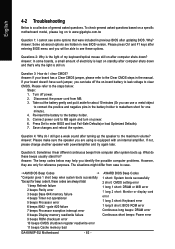
...). 7. gate A20 failure 7 beeps Processor exception interrupt error 8 beeps Display memory read/write failure 9 beeps ROM checksum error 10 beeps CMOS shutdown register read/write error 11 beeps Cache memory bad GA-K8NXP-SLI Motherboard - 82 - Why? Answer: If your board doesn't have such jumper...power. 6. English 4-2 Troubleshooting Below is a collection of general asked questions based on a specific motherboard model, please log on to www.gigabyte.com.tw Question 1: I cannot see these beeps usually stand for? Save changes and reboot the system. Question 5: Sometimes I clear ...
...). 7. gate A20 failure 7 beeps Processor exception interrupt error 8 beeps Display memory read/write failure 9 beeps ROM checksum error 10 beeps CMOS shutdown register read/write error 11 beeps Cache memory bad GA-K8NXP-SLI Motherboard - 82 - Why? Answer: If your board doesn't have such jumper...power. 6. English 4-2 Troubleshooting Below is a collection of general asked questions based on a specific motherboard model, please log on to www.gigabyte.com.tw Question 1: I cannot see these beeps usually stand for? Save changes and reboot the system. Question 5: Sometimes I clear ...


