User Manual
Page 1
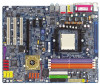
GA-K8NXP-9 AMD Socket 939 Processor Motherboard User's Manual Rev. 1003 12ME-K8NXP9-1003
GA-K8NXP-9 AMD Socket 939 Processor Motherboard User's Manual Rev. 1003 12ME-K8NXP9-1003

User Manual
Page 2
Motherboard GA-K8NXP-9 Dec. 22, 2004 Motherboard GA-K8NXP-9 Dec. 22, 2004
Motherboard GA-K8NXP-9 Dec. 22, 2004 Motherboard GA-K8NXP-9 Dec. 22, 2004
User Manual
Page 4
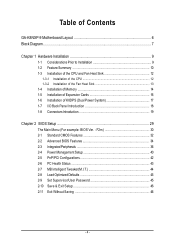
Table of Contents GA-K8NXP-9 Motherboard Layout 6 Block Diagram ...7 Chapter 1 Hardware Installation 9 1-1 Considerations Prior to Installation 9 1-2 Feature Summary 10 1-3 Installation of the CPU and Fan Heat Sink 12 1-3-1 Installation of the ...
Table of Contents GA-K8NXP-9 Motherboard Layout 6 Block Diagram ...7 Chapter 1 Hardware Installation 9 1-1 Considerations Prior to Installation 9 1-2 Feature Summary 10 1-3 Installation of the CPU and Fan Heat Sink 12 1-3-1 Installation of the ...
User Manual
Page 9
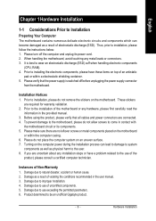
... these items on the computer power during the installation process can become damaged as a result of the motherboard or any metal leads or connectors. 3. Thus, prior to be an unofficial Gigabyte product. - 9 - Please make sure there are required for warranty validation. 2. Prior to come ...in the provided manual. 3. To prevent damage to the motherboard, please do not allow screws to installing the electronic components, ...
... these items on the computer power during the installation process can become damaged as a result of the motherboard or any metal leads or connectors. 3. Thus, prior to be an unofficial Gigabyte product. - 9 - Please make sure there are required for warranty validation. 2. Prior to come ...in the provided manual. 3. To prevent damage to the motherboard, please do not allow screws to installing the electronic components, ...
User Manual
Page 10
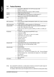
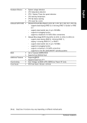
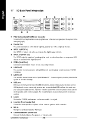
GA-K8NXP-9 Motherboard - 10 - Line Out (Front Speaker Out) ; Surround Speaker Out (Rear Speaker Out) ; Center/Subwoofer Speaker Out ; MIC ; Side Speaker Out connection Š SPDIF In/Out ...
GA-K8NXP-9 Motherboard - 10 - Line Out (Front Speaker Out) ; Surround Speaker Out (Rear Speaker Out) ; Center/Subwoofer Speaker Out ; MIC ; Side Speaker Out connection Š SPDIF In/Out ...
User Manual
Page 11
...) Over Voltage via BIOS (CPU/ DDR/Core Power/ HT-Link) ATX form factor; 30.5cm x 24.4cm (Note) EasyTune 5 functions may vary depending on different motherboards. - 11 - supports data striping (RAID 0) or mirroring (RAID 1) function or RAID 0+1 - supports hot plugging function - Hardware Installation supported on the Win 2003/2000/XP operating...
...) Over Voltage via BIOS (CPU/ DDR/Core Power/ HT-Link) ATX form factor; 30.5cm x 24.4cm (Note) EasyTune 5 functions may vary depending on different motherboards. - 11 - supports data striping (RAID 0) or mirroring (RAID 1) function or RAID 0+1 - supports hot plugging function - Hardware Installation supported on the Win 2003/2000/XP operating...

User Manual
Page 12
... damage of the CPU and Fan Heat Sink Before installing the CPU, please comply with the following conditions: 1. GA-K8NXP-9 Motherboard - 12 - Please take note of the one indented corner of the motherboard) prior to the CPU lever. If you install the CPU in Figure 2. Please make sure that the CPU ...pins fit perfectly into position making sure that the motherboard supports the CPU. 2. The pin 1 location is not recommended that the system bus frequency be set the CPU host frequency in Figure 1.(90o...
... damage of the CPU and Fan Heat Sink Before installing the CPU, please comply with the following conditions: 1. GA-K8NXP-9 Motherboard - 12 - Please take note of the one indented corner of the motherboard) prior to the CPU lever. If you install the CPU in Figure 2. Please make sure that the CPU ...pins fit perfectly into position making sure that the motherboard supports the CPU. 2. The pin 1 location is not recommended that the system bus frequency be set the CPU host frequency in Figure 1.(90o...

User Manual
Page 13
... 1-3-2 Installation of the Fan Heat Sink Fig.1 Before installing the fan heat sink, please first add an even layer of heat sink paste on the motherboard so that either thermal tape rather than heat sink paste be used for detailed installation instructions). To prevent such an occurrence, it is suggested that...
... 1-3-2 Installation of the Fan Heat Sink Fig.1 Before installing the fan heat sink, please first add an even layer of heat sink paste on the motherboard so that either thermal tape rather than heat sink paste be used for detailed installation instructions). To prevent such an occurrence, it is suggested that...
User Manual
Page 14
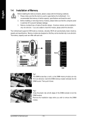
...sure that they can be inserted only in one direction. Then push it down. A memory module can be installed in one direction. The motherboard supports DDR memory modules, whereby BIOS will automatically detect memory capacity and specifications. Notch DDR Fig.1 The DIMM socket has a notch, so... that the memory used is recommended that memory of similar capacity, specifications and brand be used can only fit in only one direction. GA-K8NXP-9 Motherboard - 14 - Insert the DIMM memory module vertically into the DIMM socket. Fig.2 Close the plastic clip at both edges of the ...
...sure that they can be inserted only in one direction. Then push it down. A memory module can be installed in one direction. The motherboard supports DDR memory modules, whereby BIOS will automatically detect memory capacity and specifications. Notch DDR Fig.1 The DIMM socket has a notch, so... that the memory used is recommended that memory of similar capacity, specifications and brand be used can only fit in only one direction. GA-K8NXP-9 Motherboard - 14 - Insert the DIMM memory module vertically into the DIMM socket. Fig.2 Close the plastic clip at both edges of the ...
User Manual
Page 16
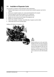
.... 6. Replace the screw to install/uninstall the VGA card. Replace your VGA card is locked by following the steps outlined below: 1. GA-K8NXP-9 Motherboard - 16 - Installing a PCI Express x 16 expansion card: Please carefully pull out the small whitedrawable bar at the end of expansion card... sure your computer's chassis cover. 7. Power on the slot. Be sure the metal contacts on the card are indeed seated in motherboard. 4. Read the related expansion card's instruction document before install the expansion card into expansion slot in the slot. 5. Install related driver ...
.... 6. Replace the screw to install/uninstall the VGA card. Replace your VGA card is locked by following the steps outlined below: 1. GA-K8NXP-9 Motherboard - 16 - Installing a PCI Express x 16 expansion card: Please carefully pull out the small whitedrawable bar at the end of expansion card... sure your computer's chassis cover. 7. Power on the slot. Be sure the metal contacts on the card are indeed seated in motherboard. 4. Read the related expansion card's instruction document before install the expansion card into expansion slot in the slot. 5. Install related driver ...

User Manual
Page 17
... the Dual Power System function. The K8DPS socket (VRM_CONN) has a notch, so the K8DPS can only fit in a Dual Power System: Parallel Mode-K8DPS and motherboard CPU power can provide you want to install K8DPS? 1. Hardware Installation English 1-6 Installation of 6-phase power circuit. K8DPS (Dual Power System) is K8DPS? A cool ...stylish neon blue K8DPS that supplies a total 6-phase power circuit design, delivers a high durable power design for the new generation motherboard. Insert the K8DPS vertically into the socket and then push it down. 3.
... the Dual Power System function. The K8DPS socket (VRM_CONN) has a notch, so the K8DPS can only fit in a Dual Power System: Parallel Mode-K8DPS and motherboard CPU power can provide you want to install K8DPS? 1. Hardware Installation English 1-6 Installation of 6-phase power circuit. K8DPS (Dual Power System) is K8DPS? A cool ...stylish neon blue K8DPS that supplies a total 6-phase power circuit design, delivers a high durable power design for the new generation motherboard. Insert the K8DPS vertically into the socket and then push it down. 3.
User Manual
Page 18
... connected to MIC In jack. SPDIF_O (SPDIF Out) The SPDIF output is capable of 10/100/1000Mbps. Line In Devices like CD-ROM, walkman etc. GA-K8NXP-9 Motherboard - 18 - USB port Before you connect your device(s) into USB connector(s), please make sure your OS does not support USB controller, please contact OS ven...
... connected to MIC In jack. SPDIF_O (SPDIF Out) The SPDIF output is capable of 10/100/1000Mbps. Line In Devices like CD-ROM, walkman etc. GA-K8NXP-9 Motherboard - 18 - USB port Before you connect your device(s) into USB connector(s), please make sure your OS does not support USB controller, please contact OS ven...

User Manual
Page 20
... is recommended that a power supply that can supply enough stable power to all components and devices are properly installed. Please remove the sticker on the motherboard and connect tightly. If a power supply is used (300W or greater). Definition 1 3 1 GND 2 GND 2 4 3 +12V 4 +12V 12 24 Pin No...12V(Onlyfor24-pinATX) 23 +5V (Only for 24-pin ATX) 1 13 12 3.3V(Onlyfor24-pin ATX) 24 GND(Only for 24-pin ATX) GA-K8NXP-9 Motherboard - 20 - If the ATX_12V power connector is not connected, the system will not start . English 1/2) ATX_12V/ATX (Power Connector) With the ...
... is recommended that a power supply that can supply enough stable power to all components and devices are properly installed. Please remove the sticker on the motherboard and connect tightly. If a power supply is used (300W or greater). Definition 1 3 1 GND 2 GND 2 4 3 +12V 4 +12V 12 24 Pin No...12V(Onlyfor24-pinATX) 23 +5V (Only for 24-pin ATX) 1 13 12 3.3V(Onlyfor24-pin ATX) 24 GND(Only for 24-pin ATX) GA-K8NXP-9 Motherboard - 20 - If the ATX_12V power connector is not connected, the system will not start . English 1/2) ATX_12V/ATX (Power Connector) With the ...
User Manual
Page 22
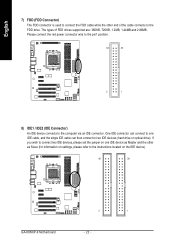
If you wish to connect two IDE devices, please set the jumper on the IDE device). 40 39 2 1 GA-K8NXP-9 Motherboard - 22 - Please connect the red power connector wire to the pin1 position. 34 33 2 1 8) IDE1 / IDE2 (IDE Connector) An IDE device connects to the computer ...
If you wish to connect two IDE devices, please set the jumper on the IDE device). 40 39 2 1 GA-K8NXP-9 Motherboard - 22 - Please connect the red power connector wire to the pin1 position. 34 33 2 1 8) IDE1 / IDE2 (IDE Connector) An IDE device connects to the computer ...

User Manual
Page 24
... 1: Power Pin 2- Pin 3: NC Pin 4: Data(-) Open: Normal Close: Reset Hardware System Open: Normal Close: Power On/Off Pin 1: LED anode(+) Pin 2: LED cathode(-) NC GA-K8NXP-9 Motherboard - 24 - Speaker Connector Power Switch Message LED/ Power/ Sleep LED SPEAK- 20 19 SPEAK+ PWPW+ MSGMSG+ 21 NCRES+ RES- English 12) F_PANEL (Front Panel Jumper...
... 1: Power Pin 2- Pin 3: NC Pin 4: Data(-) Open: Normal Close: Reset Hardware System Open: Normal Close: Power On/Off Pin 1: LED anode(+) Pin 2: LED cathode(-) NC GA-K8NXP-9 Motherboard - 24 - Speaker Connector Power Switch Message LED/ Power/ Sleep LED SPEAK- 20 19 SPEAK+ PWPW+ MSGMSG+ 21 NCRES+ RES- English 12) F_PANEL (Front Panel Jumper...

User Manual
Page 26
.../CIR cable, please contact your local dealer. 2 10 1 9 Pin No. 1 2 3 4 5 6 7 8 9 10 Definition Power Power USB DXUSB DyUSB DX+ USB Dy+ GND GND No Pin NC GA-K8NXP-9 Motherboard - 26 - Be careful with the polarity of the front USB connector. To use IR function only, please connect IR module to Pin1 to work or...
.../CIR cable, please contact your local dealer. 2 10 1 9 Pin No. 1 2 3 4 5 6 7 8 9 10 Definition Power Power USB DXUSB DyUSB DX+ USB Dy+ GND GND No Pin NC GA-K8NXP-9 Motherboard - 26 - Be careful with the polarity of the front USB connector. To use IR function only, please connect IR module to Pin1 to work or...

User Manual
Page 28
GA-K8NXP-9 Motherboard - 28 - Replace only with the same or equivalent type recommended by the manufacturer. If you can use a metal object to connect the positive and negative ...
GA-K8NXP-9 Motherboard - 28 - Replace only with the same or equivalent type recommended by the manufacturer. If you can use a metal object to connect the positive and negative ...
User Manual
Page 29
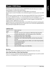
... first time, it is a Windows-based utility that you to a new BIOS, either Gigabyte's Q-Flash or @BIOS utility can enter the BIOS setup screen by pressing "Ctrl + F1". When the power is displayed at the bottom of the motherboard. English Chapter 2 BIOS Setup BIOS (Basic Input and Output System) includes a CMOS SETUP... Information Save all the CMOS changes, only for Main Menu Main Menu The on-line description of the highlighted setup function is turned on the motherboard supplies the necessary power to select item Select Item Main Menu - To exit the Help Window press . - 29 -
... first time, it is a Windows-based utility that you to a new BIOS, either Gigabyte's Q-Flash or @BIOS utility can enter the BIOS setup screen by pressing "Ctrl + F1". When the power is displayed at the bottom of the motherboard. English Chapter 2 BIOS Setup BIOS (Basic Input and Output System) includes a CMOS SETUP... Information Save all the CMOS changes, only for Main Menu Main Menu The on-line description of the highlighted setup function is turned on the motherboard supplies the necessary power to select item Select Item Main Menu - To exit the Help Window press . - 29 -
User Manual
Page 30
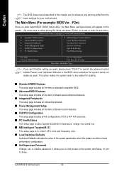
... Saving Esc: Quit F8: Dual BIOS/Q-Flash KLJI: Select Item F10: Save & Exit Setup Time, Date, Hard Disk Type... GA-K8NXP-9 Motherboard - 30 - This action makes the system reset to the default for your motherboard. CMOS Setup Utility-Copyright (C) 1984-2004 Award Software ` Standard CMOS Features ` Advanced BIOS Features ` Integrated Peripherals ` Power Management Setup...
... Saving Esc: Quit F8: Dual BIOS/Q-Flash KLJI: Select Item F10: Save & Exit Setup Time, Date, Hard Disk Type... GA-K8NXP-9 Motherboard - 30 - This action makes the system reset to the default for your motherboard. CMOS Setup Utility-Copyright (C) 1984-2004 Award Software ` Standard CMOS Features ` Advanced BIOS Features ` Integrated Peripherals ` Power Management Setup...
User Manual
Page 32
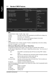
... base on this if no IDE devices are : CHS/LBA/Large/Auto(default:Auto) Capacity Capacity of heads Precomp Write precomp Landing Zone Landing zone GA-K8NXP-9 Motherboard - 32 - Hard drive information should be labeled on the outside drive casing. English 2-1 Standard CMOS Features Date (mm:dd:yy) Time (hh:mm:ss) CMOS...
... base on this if no IDE devices are : CHS/LBA/Large/Auto(default:Auto) Capacity Capacity of heads Precomp Write precomp Landing Zone Landing zone GA-K8NXP-9 Motherboard - 32 - Hard drive information should be labeled on the outside drive casing. English 2-1 Standard CMOS Features Date (mm:dd:yy) Time (hh:mm:ss) CMOS...


