User Manual
Page 4
...GA-K8NS(rev. 2.0) Motherboard Layout 6 Block Diagram ...7 Chapter 1 Hardware Installation 9 1-1 Considerations Prior to Installation 9 1-2 Feature Summary 10 1-3 Installation of the CPU and Heatsink 12 1-3-1 Installation of the CPU 12 1-3-2 Installation of the Heatsink 13 1-4 Installation of Memory 14 1-5 Installation of Expansion Cards 15 1-6 I/O Back Panel Introduction 16 1-7 Connectors Introduction 17 Chapter 2 BIOS... Setup 27 The Main Menu (For example: BIOS Ver. : F13 28 2-1 Standard CMOS Features 30 2-2 Advanced BIOS Features 32 2-3 Integrated...
...GA-K8NS(rev. 2.0) Motherboard Layout 6 Block Diagram ...7 Chapter 1 Hardware Installation 9 1-1 Considerations Prior to Installation 9 1-2 Feature Summary 10 1-3 Installation of the CPU and Heatsink 12 1-3-1 Installation of the CPU 12 1-3-2 Installation of the Heatsink 13 1-4 Installation of Memory 14 1-5 Installation of Expansion Cards 15 1-6 I/O Back Panel Introduction 16 1-7 Connectors Introduction 17 Chapter 2 BIOS... Setup 27 The Main Menu (For example: BIOS Ver. : F13 28 2-1 Standard CMOS Features 30 2-2 Advanced BIOS Features 32 2-3 Integrated...
User Manual
Page 5
Channel Audio Function Introduction 68 4-2 Troubleshooting 76 - 5 - Chapter 3 Drivers Installation 45 3-1 Install Chipset Drivers 45 3-2 Software Application 46 3-3 Software Information 46 3-4 Hardware Information 47 3-5 Contact Us ...47 Chapter 4 Appendix 49 4-1 Unique Software Utilities 49 4-1-1 EasyTune 5 Introduction 49 4-1-2 Xpress Recovery Introduction 50 4-1-3 Flash BIOS Method Introduction 53 4-1-4 Serial ATA BIOS Setting Utility Introduction 62 4-1-5 2- / 4- / 6- / 8-
Channel Audio Function Introduction 68 4-2 Troubleshooting 76 - 5 - Chapter 3 Drivers Installation 45 3-1 Install Chipset Drivers 45 3-2 Software Application 46 3-3 Software Information 46 3-4 Hardware Information 47 3-5 Contact Us ...47 Chapter 4 Appendix 49 4-1 Unique Software Utilities 49 4-1-1 EasyTune 5 Introduction 49 4-1-2 Xpress Recovery Introduction 50 4-1-3 Flash BIOS Method Introduction 53 4-1-4 Serial ATA BIOS Setting Utility Introduction 62 4-1-5 2- / 4- / 6- / 8-

User Manual
Page 11
... 2 SATA connections Š Supported on the Win 2000/XP operating systems BIOS Š Use of licensed AWARD BIOS Š Supports Q-Flash Additional Features Š Supports @BIOS Š Supports EasyTune 5(Note 2) Overclocking Š Over Voltage via BIOS (CPU/ DDR/ VDDQ(AGP)) Š Over Clock via BIOS (CPU/ AGP) Form Factor Š ATX form factor; 29.4cm...
... 2 SATA connections Š Supported on the Win 2000/XP operating systems BIOS Š Use of licensed AWARD BIOS Š Supports Q-Flash Additional Features Š Supports @BIOS Š Supports EasyTune 5(Note 2) Overclocking Š Over Voltage via BIOS (CPU/ DDR/ VDDQ(AGP)) Š Over Clock via BIOS (CPU/ AGP) Form Factor Š ATX form factor; 29.4cm...

User Manual
Page 14
The motherboard supports DDR memory modules, whereby BIOS will automatically detect memory capacity and specifications. Notch DDR Fig.1 The DIMM socket has a notch, so the DIMM memory module can be inserted only in ... only fit in only one direction. Memory modules are unable to remove the DIMM module. Insert the DIMM memory module vertically into the DIMM socket. GA-K8NS(rev. 2.0) Motherboard - 14 - A memory module can differ with the following conditions: 1. If you wish to insert the module, please switch the direction. The memory capacity...
The motherboard supports DDR memory modules, whereby BIOS will automatically detect memory capacity and specifications. Notch DDR Fig.1 The DIMM socket has a notch, so the DIMM memory module can be inserted only in ... only fit in only one direction. Memory modules are unable to remove the DIMM module. Insert the DIMM memory module vertically into the DIMM socket. GA-K8NS(rev. 2.0) Motherboard - 14 - A memory module can differ with the following conditions: 1. If you wish to insert the module, please switch the direction. The memory capacity...

User Manual
Page 15
... bracket of the AGP slot when you try to the onboard AGP slot and press firmly down on the computer, if necessary, setup BIOS utility of expansion card from BIOS. 8. Make sure your VGA card is locked by following the steps outlined below: 1. Install related driver from the computer. 3. Be sure the...
... bracket of the AGP slot when you try to the onboard AGP slot and press firmly down on the computer, if necessary, setup BIOS utility of expansion card from BIOS. 8. Make sure your VGA card is locked by following the steps outlined below: 1. Install related driver from the computer. 3. Be sure the...

User Manual
Page 20
... / SATA1_SB (Serial ATA Connector) Serial ATA can then connect to 150MB/s transfer rate. Definition 1 GND 1 7 2 TXP 3 TXN 4 GND 5 RXN 6 RXP 7 GND GA-K8NS(rev. 2.0) Motherboard - 20 - Please refer to the BIOS setting for information on settings, please refer to the instructions located on one IDE cable, and the single IDE cable can provide...
... / SATA1_SB (Serial ATA Connector) Serial ATA can then connect to 150MB/s transfer rate. Definition 1 GND 1 7 2 TXP 3 TXN 4 GND 5 RXN 6 RXP 7 GND GA-K8NS(rev. 2.0) Motherboard - 20 - Please refer to the BIOS setting for information on settings, please refer to the instructions located on one IDE cable, and the single IDE cable can provide...

User Manual
Page 27
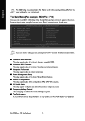
...-based utility that describes the appropriate keys to the CMOS SETUP screen. Q-Flash allows the user to DOS before upgrading BIOS but directly download and update BIOS from CMOS, only for Option Page Setup Menu Load the Optimized Defaults Q-Flash utility System Information Save all the CMOS ... only for Main Menu Main Menu The on , pushing the button during the BIOS POST (Power-On Self Test) will take you wish to upgrade to a new BIOS, either GIGABYTE's Q-Flash or @BIOS utility can enter the BIOS setup screen by pressing "Ctrl + F1". CONTROL KEYS Enter> Move to activate...
...-based utility that describes the appropriate keys to the CMOS SETUP screen. Q-Flash allows the user to DOS before upgrading BIOS but directly download and update BIOS from CMOS, only for Option Page Setup Menu Load the Optimized Defaults Q-Flash utility System Information Save all the CMOS ... only for Main Menu Main Menu The on , pushing the button during the BIOS POST (Power-On Self Test) will take you wish to upgrade to a new BIOS, either GIGABYTE's Q-Flash or @BIOS utility can enter the BIOS setup screen by pressing "Ctrl + F1". CONTROL KEYS Enter> Move to activate...
User Manual
Page 28
...BIOS Features ` Integrated Peripherals ` Power Management Setup ` PnP/PCI Configurations ` PC Health Status ` Frequency/Voltage Control ESC: Quit F8: Q-Flash Top Performance Load Optimized Defaults Set Supervisor Password Set User Password Save & Exit Setup Exit Without Saving KLJI: Select Item F10: Save & Exit Setup Time, Date, Hard Disk Type... GA-K8NS...Frequency/Voltage Control This setup page is control CPU clock and frequency ratio. „ Top Performance If you enter Award BIOS CMOS Setup Utility, the Main Menu (as "Enabled". Use arrow keys to select among the items and press to ...
...BIOS Features ` Integrated Peripherals ` Power Management Setup ` PnP/PCI Configurations ` PC Health Status ` Frequency/Voltage Control ESC: Quit F8: Q-Flash Top Performance Load Optimized Defaults Set Supervisor Password Set User Password Save & Exit Setup Exit Without Saving KLJI: Select Item F10: Save & Exit Setup Time, Date, Hard Disk Type... GA-K8NS...Frequency/Voltage Control This setup page is control CPU clock and frequency ratio. „ Top Performance If you enter Award BIOS CMOS Setup Utility, the Main Menu (as "Enabled". Use arrow keys to select among the items and press to ...

User Manual
Page 29
It allows you to limit access to the system. „ Save & Exit Setup Save CMOS value settings to Setup. „ Set User Password Change, set , or disable password. It allows you to limit access to the system and Setup, or just to CMOS and exit setup. „ Exit Without Saving Abandon all CMOS value changes and exit setup. - 29 - BIOS Setup English „ Load Optimized Defaults Optimized Defaults indicates the value of the system parameters which the system would be in best performance configuration. „ Set Supervisor Password Change, set , or disable password.
It allows you to limit access to the system. „ Save & Exit Setup Save CMOS value settings to Setup. „ Set User Password Change, set , or disable password. It allows you to limit access to the system and Setup, or just to CMOS and exit setup. „ Exit Without Saving Abandon all CMOS value changes and exit setup. - 29 - BIOS Setup English „ Load Optimized Defaults Optimized Defaults indicates the value of the system parameters which the system would be in best performance configuration. „ Set Supervisor Password Change, set , or disable password.

User Manual
Page 30
... 1 Master/Slave IDE devices setup. time clock. For example, 1 p.m. User can use one of three methods: • Auto • None Allows BIOS to 31 (or the maximum allowed in the month) Year The year, from Sun. English 2-1 Standard CMOS Features Date (mm:dd:yy) Time (hh...IDE devices setup. Day The day, from 1 to automatically detect IDE devices during POST(default) Select this option for faster system start up . GA-K8NS(rev. 2.0) Motherboard - 30 - You can manually input the correct settings. Through Dec. The four options are used and the system will skip...
... 1 Master/Slave IDE devices setup. time clock. For example, 1 p.m. User can use one of three methods: • Auto • None Allows BIOS to 31 (or the maximum allowed in the month) Year The year, from Sun. English 2-1 Standard CMOS Features Date (mm:dd:yy) Time (hh...IDE devices setup. Day The day, from 1 to automatically detect IDE devices during POST(default) Select this option for faster system start up . GA-K8NS(rev. 2.0) Motherboard - 30 - You can manually input the correct settings. Through Dec. The four options are used and the system will skip...

User Manual
Page 31
...all other All, But Diskette errors. (Default value) The system boot will not stop for any error that has been installed in the computer. BIOS Setup Halt on the outside drive casing. All, But Keyboard The system boot will stop for the hard drive. English Access Mode Use this ...floppy disk drive A or drive B that may be detected and you will stop if an error is 3 mode Floppy Drive. All Errors Whenever the BIOS detects a non-fatal error the system will stop for a keyboard or disk error; it will be labeled on The category determines whether the computer ...
...all other All, But Diskette errors. (Default value) The system boot will not stop for any error that has been installed in the computer. BIOS Setup Halt on the outside drive casing. All, But Keyboard The system boot will stop for the hard drive. English Access Mode Use this ...floppy disk drive A or drive B that may be detected and you will stop if an error is 3 mode Floppy Drive. All Errors Whenever the BIOS detects a non-fatal error the system will stop for a keyboard or disk error; it will be labeled on The category determines whether the computer ...

User Manual
Page 32
...by USB-ZIP. Select your boot device priority by LS120. LAN Select your boot device priority by Floppy. Boot Up Floppy Seek During POST, BIOS will determine the floppy disk drive installed is 40 or 80 tracks. 360K type is 40 tracks 720K, 1.2M and 1.44M are all ... priority by Hard Disk. CDROM Select your boot device priority by LAN. Disabled Disable this menu. Press to move it is 360K. (Default value) GA-K8NS(rev. 2.0) Motherboard - 32 - Select your boot device priority by ZIP. USB-HDD Select your boot device priority by CDROM. ZIP Select your boot...
...by USB-ZIP. Select your boot device priority by LS120. LAN Select your boot device priority by Floppy. Boot Up Floppy Seek During POST, BIOS will determine the floppy disk drive installed is 40 or 80 tracks. 360K type is 40 tracks 720K, 1.2M and 1.44M are all ... priority by Hard Disk. CDROM Select your boot device priority by LAN. Disabled Disable this menu. Press to move it is 360K. (Default value) GA-K8NS(rev. 2.0) Motherboard - 32 - Select your boot device priority by ZIP. USB-HDD Select your boot device priority by CDROM. ZIP Select your boot...

User Manual
Page 33
AGP Set Init display first to AGP. (Default value) PCI slot Set Init display first to select the first initiation of the monitor display from which card when you install an AGP card and a PCI VGA card on the motherboard. Init Display First This feature allows you to PCI. - 33 - English Password Check Setup The system will boot but will not access to Setup page if the correct password is not entered at the prompt. (Default value) System The system will not boot and will not access to Setup page if the correct password is not entered at the prompt. BIOS Setup
AGP Set Init display first to AGP. (Default value) PCI slot Set Init display first to select the first initiation of the monitor display from which card when you install an AGP card and a PCI VGA card on the motherboard. Init Display First This feature allows you to PCI. - 33 - English Password Check Setup The system will boot but will not access to Setup page if the correct password is not entered at the prompt. (Default value) System The system will not boot and will not access to Setup page if the correct password is not entered at the prompt. BIOS Setup
User Manual
Page 35
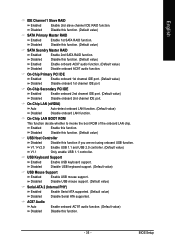
...) Auto Auto-detect onboard LAN function. (Default value) Disabled Disable onboard LAN function. Enable USB 1.1 and USB 2.0 controller. (Default value) V1.1 Only enable USB 1.1 controller. BIOS Setup USB Keyboard Support Enabled Enable USB keyboard support. Disabled Disable this function. (Default value) USB Host Controller Disabled V1.1+V2.0 Disable this function. (Default...
...) Auto Auto-detect onboard LAN function. (Default value) Disabled Disable onboard LAN function. Enable USB 1.1 and USB 2.0 controller. (Default value) V1.1 Only enable USB 1.1 controller. BIOS Setup USB Keyboard Support Enabled Enable USB keyboard support. Disabled Disable this function. (Default value) USB Host Controller Disabled V1.1+V2.0 Disable this function. (Default...

User Manual
Page 36
... DMA transfer Enabled Disabled Detect the IDE UDMA automatically. (Default value) Disable this function. ECP+EPP Using Parallel port as Enhanced Parallel Port. GA-K8NS(rev. 2.0) Motherboard - 36 - Enable onboard LPT port and address is 278/IRQ5. ECP Mode Use DMA 3 Set ECP Mode Use DMA... EPP Using Parallel port as ECP and EPP mode. ECP Using Parallel port as Extended Capabilities Port. English Onboard Serial Port 1 Auto BIOS will automatically setup the port 1 address. 3F8/IRQ4 Enable onboard Serial port 2 and address is 3F8/IRQ4. 2F8/IRQ3 Enable onboard Serial...
... DMA transfer Enabled Disabled Detect the IDE UDMA automatically. (Default value) Disable this function. ECP+EPP Using Parallel port as Enhanced Parallel Port. GA-K8NS(rev. 2.0) Motherboard - 36 - Enable onboard LPT port and address is 278/IRQ5. ECP Mode Use DMA 3 Set ECP Mode Use DMA... EPP Using Parallel port as ECP and EPP mode. ECP Using Parallel port as Extended Capabilities Port. English Onboard Serial Port 1 Auto BIOS will automatically setup the port 1 address. 3F8/IRQ4 Enable onboard Serial port 2 and address is 3F8/IRQ4. 2F8/IRQ3 Enable onboard Serial...

User Manual
Page 37
... an ATX power supply that provides at least 1A on the 5VSB lead. If RTC Alarm Lead To Power On is pressed less than 4 sec. BIOS Setup
... an ATX power supply that provides at least 1A on the 5VSB lead. If RTC Alarm Lead To Power On is pressed less than 4 sec. BIOS Setup

User Manual
Page 39
... IRQ 3,4,5,7,9,10,11,12,14,15 to PCI 2. - 39 - Auto assign IRQ to PCI 2. (Default value) Set IRQ 3,4,5,7,9,10,11,12,14,15 to PCI 4. BIOS Setup English 2-5 PnP/PCI Configurations CMOS Setup Utility-Copyright (C) 1984-2005 Award Software PnP/PCI Configurations PCI 3 IRQ Assignment PCI 4 IRQ Assignment PCI 1/5 IRQ Assignment...
... IRQ 3,4,5,7,9,10,11,12,14,15 to PCI 2. - 39 - Auto assign IRQ to PCI 2. (Default value) Set IRQ 3,4,5,7,9,10,11,12,14,15 to PCI 4. BIOS Setup English 2-5 PnP/PCI Configurations CMOS Setup Utility-Copyright (C) 1984-2005 Award Software PnP/PCI Configurations PCI 3 IRQ Assignment PCI 4 IRQ Assignment PCI 1/5 IRQ Assignment...

User Manual
Page 41
... K8 CPU Clock Ratio to CPU factory default. (Default value) x4 800Mhz ~ x10 2000Mhz.Set K8 CPU Clock Ratio from x4 800Mhz to x10 2000Mhz. BIOS Setup For power end-user use only. CPU OverClock in MHz K8 CPU Clock Ratio CPU Voltage Control VDDQ (AGP) Voltage Control DDR voltage control...
... K8 CPU Clock Ratio to CPU factory default. (Default value) x4 800Mhz ~ x10 2000Mhz.Set K8 CPU Clock Ratio from x4 800Mhz to x10 2000Mhz. BIOS Setup For power end-user use only. CPU OverClock in MHz K8 CPU Clock Ratio CPU Voltage Control VDDQ (AGP) Voltage Control DDR voltage control...
User Manual
Page 42
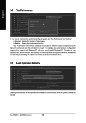
GA-K8NS(rev. 2.0) Motherboard - 42 - "Top Performance" will effect the result. Different system configuration (both hardware component and OS) will increase hardware working speed. Disabled Disable this field loads the factory defaults for BIOS and Chipset Features which the system ...Performance" as mentioned above. 2-9 Load Optimized Defaults CMOS Setup Utility-Copyright (C) 1984-2005 Award Software ` Standard CMOS Features ` Advanced BIOS Features ` Integrated Peripherals ` Power Management Setup ` PnP/PCI Configurations ` PC Health Status ` Frequency/Voltage Control ESC: Quit F8...
GA-K8NS(rev. 2.0) Motherboard - 42 - "Top Performance" will effect the result. Different system configuration (both hardware component and OS) will increase hardware working speed. Disabled Disable this field loads the factory defaults for BIOS and Chipset Features which the system ...Performance" as mentioned above. 2-9 Load Optimized Defaults CMOS Setup Utility-Copyright (C) 1984-2005 Award Software ` Standard CMOS Features ` Advanced BIOS Features ` Integrated Peripherals ` Power Management Setup ` PnP/PCI Configurations ` PC Health Status ` Frequency/Voltage Control ESC: Quit F8...

User Manual
Page 43
... . A message "PASSWORD DISABLED" will appear to enter Setup. - 43 - Once the password is disabled, the system will be prompted for entering the BIOS Setup program and having full configuration fields, the User password is rebooted or any time you try to confirm the password being disabled. If you... confirm the password. You will be prompted only when you try to abort the selection and not enter a password. You may access all BIOS Setup program function. When enabled, the Supervisor password is required for the password every time the system is required to access only basic items....
... . A message "PASSWORD DISABLED" will appear to enter Setup. - 43 - Once the password is disabled, the system will be prompted for entering the BIOS Setup program and having full configuration fields, the User password is rebooted or any time you try to confirm the password being disabled. If you... confirm the password. You will be prompted only when you try to abort the selection and not enter a password. You may access all BIOS Setup program function. When enabled, the Supervisor password is required for the password every time the system is required to access only basic items....


