User Manual
Page 10
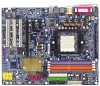
Line Out (Front Speaker Out) ; GA-K8NF-9 Motherboard - 10 - English 1-2 Feature Summary CPU Chipset Memory Slots IDE Connections FDD Connections Onboard SATA Peripherals Onboard LAN Onboard Audio Š Socket 939 for system ... devices Š Supported on the Win 2000/XP operating systems Š 1 FDD connection, allows connection of 2 FDD devices Š 4 Serial ATA ports from nVIDIA® nForce4(-4X) controller (S_ATA0_SB, S_ATA1_SB, S_ATA2_SB, S_ATA3_SB) Š Supported on the Win 2000/XP operating systems Š 1 parallel port supporting Normal/EPP/ECP mode Š 1 serial...
Line Out (Front Speaker Out) ; GA-K8NF-9 Motherboard - 10 - English 1-2 Feature Summary CPU Chipset Memory Slots IDE Connections FDD Connections Onboard SATA Peripherals Onboard LAN Onboard Audio Š Socket 939 for system ... devices Š Supported on the Win 2000/XP operating systems Š 1 FDD connection, allows connection of 2 FDD devices Š 4 Serial ATA ports from nVIDIA® nForce4(-4X) controller (S_ATA0_SB, S_ATA1_SB, S_ATA2_SB, S_ATA3_SB) Š Supported on the Win 2000/XP operating systems Š 1 parallel port supporting Normal/EPP/ECP mode Š 1 serial...

User Manual
Page 11
...; IT8712F System voltage detection CPU temperature detection CPU / System fan speed detection CPU warning temperature CPU / System fan failure warning CPU smart fan control Onboard nForce4(-4X) chipset (S_ATA0_SB, S_ATA1_SB, S_ATA2_SB, S_ATA3_SB) - supports data striping (RAID 0) or mirroring (RAID 1) function or striping + mirroring (RAID...
...; IT8712F System voltage detection CPU temperature detection CPU / System fan speed detection CPU warning temperature CPU / System fan failure warning CPU smart fan control Onboard nForce4(-4X) chipset (S_ATA0_SB, S_ATA1_SB, S_ATA2_SB, S_ATA3_SB) - supports data striping (RAID 0) or mirroring (RAID 1) function or striping + mirroring (RAID...
User Manual
Page 22
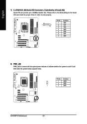
Please refer to the BIOS setting for the Serial ATA and install the proper driver in order to indicate whether the system is connect with the system power indicator to work properly. It will blink when the system enters suspend mode. Definition 1 MPD+ 2 MPD- 1 3 MPD- Pin No. Definition 1 GND 7 1 2 TXP 3 TXN 4 GND 5 RXN 6 RXP 7 GND 8) PWR_LED PWR_LED is on/off. Pin No. English 7) S_ATA0/1/2/3_SB (Serial ATA Connectors, Controlled by nForce4(-4X)) Serial ATA can provide up to 150MB/s transfer rate. GA-K8NF-9 Motherboard - 22 -
Please refer to the BIOS setting for the Serial ATA and install the proper driver in order to indicate whether the system is connect with the system power indicator to work properly. It will blink when the system enters suspend mode. Definition 1 MPD+ 2 MPD- 1 3 MPD- Pin No. Definition 1 GND 7 1 2 TXP 3 TXN 4 GND 5 RXN 6 RXP 7 GND 8) PWR_LED PWR_LED is on/off. Pin No. English 7) S_ATA0/1/2/3_SB (Serial ATA Connectors, Controlled by nForce4(-4X)) Serial ATA can provide up to 150MB/s transfer rate. GA-K8NF-9 Motherboard - 22 -

User Manual
Page 63
The RAID levels which the nVIDIA® nForce4(-4X) chipset supports are called the spare drive can be affected as long as a single physical drive to the operating system. Such a drive will be ...
The RAID levels which the nVIDIA® nForce4(-4X) chipset supports are called the spare drive can be affected as long as a single physical drive to the operating system. Such a drive will be ...