User Manual
Page 4
Table of Contents GA-K8N51PVMT-9-RH Motherboard Layout 6 Block Diagram ...7 Chapter 1 Hardware Installation 9 1-1 Considerations Prior to Installation 9 1-2 Feature Summary 10 1-3 Installation of the CPU and CPU Cooler...of Memory 14 1-5 Installation of Expansion Cards 16 1-6 I/O Back Panel Introduction 17 1-7 Connectors Introduction 19 Chapter 2 BIOS Setup 29 The Main Menu (For example: BIOS Ver. : F3a 30 2-1 Standard CMOS Features 32 2-2 Advanced BIOS Features 34 2-3 IntegratedPeripherals 36 2-4 Power Management Setup 39 2-5 PnP/PCI Configurations 41 2-6 PC Health Status 42 2-7...
Table of Contents GA-K8N51PVMT-9-RH Motherboard Layout 6 Block Diagram ...7 Chapter 1 Hardware Installation 9 1-1 Considerations Prior to Installation 9 1-2 Feature Summary 10 1-3 Installation of the CPU and CPU Cooler...of Memory 14 1-5 Installation of Expansion Cards 16 1-6 I/O Back Panel Introduction 17 1-7 Connectors Introduction 19 Chapter 2 BIOS Setup 29 The Main Menu (For example: BIOS Ver. : F3a 30 2-1 Standard CMOS Features 32 2-2 Advanced BIOS Features 34 2-3 IntegratedPeripherals 36 2-4 Power Management Setup 39 2-5 PnP/PCI Configurations 41 2-6 PC Health Status 42 2-7...

User Manual
Page 5
Chapter 3 Drivers Installation 49 3-1 Install Chipset Drivers 49 3-2 SoftwareApplication 50 3-3 Software Information 50 3-4 Hardware Information 51 3-5 Contact Us ...51 3-6 Connecting the Video Output Devices 52 Chapter 4 Appendix 53 4-1 Unique Software Utilities 53 4-1-1 EasyTune 5 Introduction 53 4-1-2 Xpress Recovery2 Introduction 54 4-1-3 Flash BIOS Method Introduction 56 4-1-4 Configuring SATA Hard Drive(s 65 4-1-5 2- / 4- / 6- / 8- Channel Audio Function Introduction 79 4-2 Troubleshooting 84 - 5 -
Chapter 3 Drivers Installation 49 3-1 Install Chipset Drivers 49 3-2 SoftwareApplication 50 3-3 Software Information 50 3-4 Hardware Information 51 3-5 Contact Us ...51 3-6 Connecting the Video Output Devices 52 Chapter 4 Appendix 53 4-1 Unique Software Utilities 53 4-1-1 EasyTune 5 Introduction 53 4-1-2 Xpress Recovery2 Introduction 54 4-1-3 Flash BIOS Method Introduction 56 4-1-4 Configuring SATA Hard Drive(s 65 4-1-5 2- / 4- / 6- / 8- Channel Audio Function Introduction 79 4-2 Troubleshooting 84 - 5 -
User Manual
Page 6
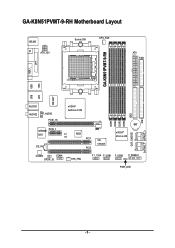
GA-K8N51PVMT-9-RH Motherboard Layout KB_MS ATX_12V Socket 939 CPU_FAN ATX FDD TV GA-K8N51PVMT-9-RH LPT VGA 1394 USB W83627 LAN USB AUDIO1 AUDIO2 F_AUDIO PCIE_16 nVIDIA® GeForce 6150 VITESSE PCIE_1 8201 CI CD_IN BIOS PCI1 PCI2 VIA VT6307 DDR1 DDR2 DDR3 DDR4 IDE2 BAT nVIDIA® nForce 430 CLR_CMOS CODEC COMA SPDIF_IO SYS_FAN F1_1394 F_USB1 F_USB2 F_PANEL1 PWR_LED IDE1 SATAII0_1 SATAII2_3 - 6 -
GA-K8N51PVMT-9-RH Motherboard Layout KB_MS ATX_12V Socket 939 CPU_FAN ATX FDD TV GA-K8N51PVMT-9-RH LPT VGA 1394 USB W83627 LAN USB AUDIO1 AUDIO2 F_AUDIO PCIE_16 nVIDIA® GeForce 6150 VITESSE PCIE_1 8201 CI CD_IN BIOS PCI1 PCI2 VIA VT6307 DDR1 DDR2 DDR3 DDR4 IDE2 BAT nVIDIA® nForce 430 CLR_CMOS CODEC COMA SPDIF_IO SYS_FAN F1_1394 F_USB1 F_USB2 F_PANEL1 PWR_LED IDE1 SATAII0_1 SATAII2_3 - 6 -

User Manual
Page 11
...CPU warning temperature Š CPU /system fan failure warning Š CPU smart fan control (Note 3) BIOS Š 1 4Mbit flash ROM Š Use of licensed AWARD BIOS Additional Features Š Supports @BIOS Š Supports Download Center Š Supports Q-Flash Š Supports EasyTune (Note 4) Š ...memory size will depend on different motherboards. - 11 - Hardware Installation For more detailed information please check at the FAQ section on GIGABYTE's website. (Note 4) EasyTune functions may vary depending on the CPU you install. For example, 4 GB of memory is reserved ...
...CPU warning temperature Š CPU /system fan failure warning Š CPU smart fan control (Note 3) BIOS Š 1 4Mbit flash ROM Š Use of licensed AWARD BIOS Additional Features Š Supports @BIOS Š Supports Download Center Š Supports Q-Flash Š Supports EasyTune (Note 4) Š ...memory size will depend on different motherboards. - 11 - Hardware Installation For more detailed information please check at the FAQ section on GIGABYTE's website. (Note 4) EasyTune functions may vary depending on the CPU you install. For example, 4 GB of memory is reserved ...
User Manual
Page 14
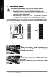
..., please switch the direction. Memory modules have a foolproof insertion design. Insert the DIMM memory module vertically into the DIMM socket. GA-K8N51PVMT-9-RH Motherboard - 14 - The motherboard supports DDR memory modules, whereby BIOS will automatically detect memory capacity and specifications. Reverse the installation steps when you are designed so that memory of similar...
..., please switch the direction. Memory modules have a foolproof insertion design. Insert the DIMM memory module vertically into the DIMM socket. GA-K8N51PVMT-9-RH Motherboard - 14 - The motherboard supports DDR memory modules, whereby BIOS will automatically detect memory capacity and specifications. Reverse the installation steps when you are designed so that memory of similar...
User Manual
Page 16
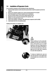
Make sure your computer's chassis cover, screws and slot bracket from the operating system. GA-K8N51PVMT-9-RH Motherboard - 16 - Press the expansion card firmly into the computer. 2. Install related driver from the computer. 3. Remove your VGA card is ...the small white-drawable bar. English 1-5 Installation of Expansion Cards You can also press the latch on the computer, if necessary, setup BIOS utility of expansion card from BIOS. 8. Read the related expansion card's instruction document before install the expansion card into expansion slot in the slot. 5. Please align ...
Make sure your computer's chassis cover, screws and slot bracket from the operating system. GA-K8N51PVMT-9-RH Motherboard - 16 - Press the expansion card firmly into the computer. 2. Install related driver from the computer. 3. Remove your VGA card is ...the small white-drawable bar. English 1-5 Installation of Expansion Cards You can also press the latch on the computer, if necessary, setup BIOS utility of expansion card from BIOS. 8. Read the related expansion card's instruction document before install the expansion card into expansion slot in the slot. 5. Please align ...

User Manual
Page 22
... 6) IDE1 / IDE2 (IDE Connector) An IDE device connects to work properly. 1 7 7 1 Pin No. 1 2 3 4 5 6 7 Definition GND TXP TXN GND RXN RXP GND GA-K8N51PVMT-9-RH Motherboard - 22 - Please refer to the BIOS setting for information on settings, please refer to the instructions located on the IDE device). 40 39 2 IDE2 1 IDE1 7) SATAII0/1/2/3 (SATA 3Gb...
... 6) IDE1 / IDE2 (IDE Connector) An IDE device connects to work properly. 1 7 7 1 Pin No. 1 2 3 4 5 6 7 Definition GND TXP TXN GND RXN RXP GND GA-K8N51PVMT-9-RH Motherboard - 22 - Please refer to the BIOS setting for information on settings, please refer to the instructions located on the IDE device). 40 39 2 IDE2 1 IDE1 7) SATAII0/1/2/3 (SATA 3Gb...

User Manual
Page 28
Pin No. To clear CMOS, temporarily short 1-2 pin. Definition 1 1 Signal 2 GND GA-K8N51PVMT-9-RH Motherboard - 28 - Default doesn't include the jumper to detect if the chassis cover is removed. English 17) CLR_CMOS (Clear CMOS) You may clear the CMOS data to its default values by this header. 1 Open: Normal 1 Short: Clear CMOS 18) CI (Chassis Intrusion, Case Open) This 2-pin connector allows your system to avoid improper use of this header. You can check the "Case Open" status in BIOS Setup.
Pin No. To clear CMOS, temporarily short 1-2 pin. Definition 1 1 Signal 2 GND GA-K8N51PVMT-9-RH Motherboard - 28 - Default doesn't include the jumper to detect if the chassis cover is removed. English 17) CLR_CMOS (Clear CMOS) You may clear the CMOS data to its default values by this header. 1 Open: Normal 1 Short: Clear CMOS 18) CI (Chassis Intrusion, Case Open) This 2-pin connector allows your system to avoid improper use of this header. You can check the "Case Open" status in BIOS Setup.
User Manual
Page 29
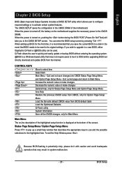
... Page Setup Menu Press to pop up BIOS for the first time, it with caution and avoid inadequate operation that BIOS needs to a new BIOS, either Gigabyte's Q-Flash or @BIOS utility can enter the BIOS setup screen by pressing "Ctrl + F1". Because BIOS flashing is displayed at the bottom of ...the motherboard. Quit and not save the current BIOS to the CMOS SETUP screen....
... Page Setup Menu Press to pop up BIOS for the first time, it with caution and avoid inadequate operation that BIOS needs to a new BIOS, either Gigabyte's Q-Flash or @BIOS utility can enter the BIOS setup screen by pressing "Ctrl + F1". Because BIOS flashing is displayed at the bottom of ...the motherboard. Quit and not save the current BIOS to the CMOS SETUP screen....

User Manual
Page 30
... only and may differ from the exact settings for your motherboard. The BIOS Setup menus described in the BIOS when somehow the system works not stable as figure below) will appear on cards) device. GA-K8N51PVMT-9-RH Motherboard - 30 - This action makes the system reset to accept...the advanced option hidden. If you can't find the setting you enter Award BIOS CMOS Setup Utility, the Main Menu (as usual. English : For Boot Menu Select boot sequence for stability. GA-K8N51PVMT-9-RH F3a . . . . :BIOS Setup/Q-Flash, : Xpress Recovery2, For Boot Menu 01/11/2006-C51-MCP51-...
... only and may differ from the exact settings for your motherboard. The BIOS Setup menus described in the BIOS when somehow the system works not stable as figure below) will appear on cards) device. GA-K8N51PVMT-9-RH Motherboard - 30 - This action makes the system reset to accept...the advanced option hidden. If you can't find the setting you enter Award BIOS CMOS Setup Utility, the Main Menu (as usual. English : For Boot Menu Select boot sequence for stability. GA-K8N51PVMT-9-RH F3a . . . . :BIOS Setup/Q-Flash, : Xpress Recovery2, For Boot Menu 01/11/2006-C51-MCP51-...

User Manual
Page 31
...Password Change, set , or disable password. English „ Standard CMOS Features This setup page includes all the items in standard compatible BIOS. „ Advanced BIOS Features This setup page includes all the items of Award special enhanced features. „ Integrated Peripherals This setup page includes all onboard ... items of Green function features. „ PnP/PCI Configuration This setup page includes all CMOS value changes and exit setup. - 31 - BIOS Setup It allows you to limit access to the system. „ Save & Exit Setup Save CMOS value settings to CMOS and exit setup...
...Password Change, set , or disable password. English „ Standard CMOS Features This setup page includes all the items in standard compatible BIOS. „ Advanced BIOS Features This setup page includes all the items of Award special enhanced features. „ Integrated Peripherals This setup page includes all onboard ... items of Green function features. „ PnP/PCI Configuration This setup page includes all CMOS value changes and exit setup. - 31 - BIOS Setup It allows you to limit access to the system. „ Save & Exit Setup Save CMOS value settings to CMOS and exit setup...

User Manual
Page 32
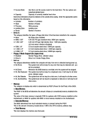
...44M, 3.5"] [Disabled] [All, But Keyboard] 640K 511M 512M 1 to 31 (or maximum allowed in the month) 1999 to Sat, determined by the BIOS and is calculated based on the 24-hour military-time clock. The day, from 1 to 31 (or the maximum allowed in . IDE Channel 0 Master...can use one of three methods: Auto Allows BIOS to automatically detect IDE devices during POST(default) Select this if no IDE devices are used and the system will skip the automatic Manual detection step and allow for faster system start up . GA-K8N51PVMT-9-RH Motherboard - 32 - IDE Channel 0 ...
...44M, 3.5"] [Disabled] [All, But Keyboard] 640K 511M 512M 1 to 31 (or maximum allowed in the month) 1999 to Sat, determined by the BIOS and is calculated based on the 24-hour military-time clock. The day, from 1 to 31 (or the maximum allowed in . IDE Channel 0 Master...can use one of three methods: Auto Allows BIOS to automatically detect IDE devices during POST(default) Select this if no IDE devices are used and the system will skip the automatic Manual detection step and allow for faster system start up . GA-K8N51PVMT-9-RH Motherboard - 32 - IDE Channel 0 ...
User Manual
Page 33
...during the POST. This is determined by POST (Power On Self Test) of memory located above 1 MB in the system. All Errors Whenever the BIOS detects a non-fatal error the system will not stop for Japan Area) Disabled Normal Floppy Drive. (Default value) Drive A Drive A is ...2.88M byte capacity. All, But Disk/Key The system boot will be prompted. Memory The category is display-only which is the amount of the BIOS. Floppy 3 Mode Support (for a disk error; Enter the appropriate option based on the motherboard. None No floppy drive installed. 360K, 5.25...
...during the POST. This is determined by POST (Power On Self Test) of memory located above 1 MB in the system. All Errors Whenever the BIOS detects a non-fatal error the system will not stop for Japan Area) Disabled Normal Floppy Drive. (Default value) Drive A Drive A is ...2.88M byte capacity. All, But Disk/Key The system boot will be prompted. Memory The category is display-only which is the amount of the BIOS. Floppy 3 Mode Support (for a disk error; Enter the appropriate option based on the motherboard. None No floppy drive installed. 360K, 5.25...

User Manual
Page 34
...to move it up, or to exit this function. Boot Up Floppy Seek During POST, BIOS will determine the floppy disk drive installed is 40 or 80 tracks. 360K type is 360K. (Default value) GA-K8N51PVMT-9-RH Motherboard - 34 - Note that there will not search for the type of floppy ...disk drive by CDROM. ZIP USB-FDD Select your boot device priority by ZIP. USB-HDD Select your boot device priority by USB-HDD. Enabled BIOS searches for onboard(or add...
...to move it up, or to exit this function. Boot Up Floppy Seek During POST, BIOS will determine the floppy disk drive installed is 40 or 80 tracks. 360K type is 360K. (Default value) GA-K8N51PVMT-9-RH Motherboard - 34 - Note that there will not search for the type of floppy ...disk drive by CDROM. ZIP USB-FDD Select your boot device priority by ZIP. USB-HDD Select your boot device priority by USB-HDD. Enabled BIOS searches for onboard(or add...

User Manual
Page 35
... on the PCI Express slot. (Default value) Always Enable Onboard GPU will always be denied if the correct password is not entered at the prompt. BIOS Setup Set Init Display First to PCI Express VGA card. (Default value) Frame Buffer Size 16M Set frame buffer size to 16MB. 32M Set frame...
... on the PCI Express slot. (Default value) Always Enable Onboard GPU will always be denied if the correct password is not entered at the prompt. BIOS Setup Set Init Display First to PCI Express VGA card. (Default value) Frame Buffer Size 16M Set frame buffer size to 16MB. 32M Set frame...

User Manual
Page 37
...support. (Default Value) Disable Serial-ATAII 2 support. Disabled Disable USB mouse support. (Default value) - 37 - IDE1 Conductor Cable Auto BIOS autodetects IDE1 conductor cable .(Default Value) ATA66/100/133 Set IDE1 Conductor Cable to ATA33. (Please make sure your IDE device and cable... On-Chip IDE Channel1 Enabled Enable onboard 2nd channel IDE port. (Default value) Disabled Disable onboard 2nd channel IDE port. BIOS Setup Disabled Disable this function. (Default value) On-Chip IDE Channel0 Enabled Enable onboard 1st channel IDE port. (Default value)...
...support. (Default Value) Disable Serial-ATAII 2 support. Disabled Disable USB mouse support. (Default value) - 37 - IDE1 Conductor Cable Auto BIOS autodetects IDE1 conductor cable .(Default Value) ATA66/100/133 Set IDE1 Conductor Cable to ATA33. (Please make sure your IDE device and cable... On-Chip IDE Channel1 Enabled Enable onboard 2nd channel IDE port. (Default value) Disabled Disable onboard 2nd channel IDE port. BIOS Setup Disabled Disable this function. (Default value) On-Chip IDE Channel0 Enabled Enable onboard 1st channel IDE port. (Default value)...

User Manual
Page 38
... Boot ROM This function decide whether to invoke the boot ROM of the onboard LAN chip. Onboard Serial Port 1 Auto 3F8/IRQ4 BIOS will automatically setup the port 1 address. GA-K8N51PVMT-9-RH Motherboard - 38 - Enable onboard LPT port and address is 378/IRQ7. (Default value) 278/IRQ5 Enable onboard LPT port and address...
... Boot ROM This function decide whether to invoke the boot ROM of the onboard LAN chip. Onboard Serial Port 1 Auto 3F8/IRQ4 BIOS will automatically setup the port 1 address. GA-K8N51PVMT-9-RH Motherboard - 38 - Enable onboard LPT port and address is 378/IRQ7. (Default value) 278/IRQ5 Enable onboard LPT port and address...

User Manual
Page 39
Disabled Disable this function. BIOS Setup English 2-4 Power Management Setup CMOS Setup Utility-Copyright (C) 1984-2006 Award Software Power Management Setup ACPI Suspend Type Soft-Off by Power button PME ...
Disabled Disable this function. BIOS Setup English 2-4 Power Management Setup CMOS Setup Utility-Copyright (C) 1984-2006 Award Software Power Management Setup ACPI Suspend Type Soft-Off by Power button PME ...

User Manual
Page 41
... IRQ 3,4,5,7,9,10,11,12,14,15 to PCI 2. - 41 - Auto assign IRQ to PCI 2. (Default value) Set IRQ 3,4,5,7,9,10,11,12,14,15 to PCI 1. BIOS Setup
... IRQ 3,4,5,7,9,10,11,12,14,15 to PCI 2. - 41 - Auto assign IRQ to PCI 2. (Default value) Set IRQ 3,4,5,7,9,10,11,12,14,15 to PCI 1. BIOS Setup

User Manual
Page 43
Users can adjust the fan speed with Easy Tune based on their requirements. (Note) Whether the CPU Smart FAN Control function is enabled, CPU fan will depend on the CPU you install. For more detailed information please check at different speed depending on CPU temperature. English CPU Smart FAN Control (Note) Disabled Disable this function. (Default value) Enabled When this function is supported will run at the FAQ section on GIGABYTE's website. - 43 - BIOS Setup
Users can adjust the fan speed with Easy Tune based on their requirements. (Note) Whether the CPU Smart FAN Control function is enabled, CPU fan will depend on the CPU you install. For more detailed information please check at different speed depending on CPU temperature. English CPU Smart FAN Control (Note) Disabled Disable this function. (Default value) Enabled When this function is supported will run at the FAQ section on GIGABYTE's website. - 43 - BIOS Setup


