User Manual
Page 4
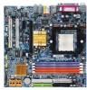
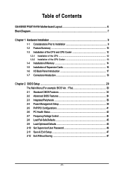
Table of Contents GA-K8N51PVMT-9-RH Motherboard Layout 6 Block Diagram ...7 Chapter 1 Hardware Installation 9 1-1 Considerations Prior to Installation 9 1-2 Feature Summary 10 1-3 Installation of the CPU and CPU Cooler 12 1-3-1 Installation of the CPU 12 1-3-2 Installation of the CPU Cooler 13 1-4 Installation of Memory 14 1-5 Installation of Expansion Cards 16 1-6 I/O Back Panel Introduction 17 1-7 Connectors Introduction 19 Chapter 2 BIOS...
Table of Contents GA-K8N51PVMT-9-RH Motherboard Layout 6 Block Diagram ...7 Chapter 1 Hardware Installation 9 1-1 Considerations Prior to Installation 9 1-2 Feature Summary 10 1-3 Installation of the CPU and CPU Cooler 12 1-3-1 Installation of the CPU 12 1-3-2 Installation of the CPU Cooler 13 1-4 Installation of Memory 14 1-5 Installation of Expansion Cards 16 1-6 I/O Back Panel Introduction 17 1-7 Connectors Introduction 19 Chapter 2 BIOS...
User Manual
Page 9
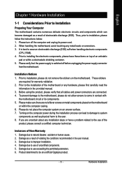
... 7. Please do not allow screws to come in the provided manual. 3. Instances of uncertified components. 5. Damage due to be an unofficial Gigabyte product. - 9 - Product determined to natural disaster, accident or human cause. 2. Hardware Installation Thus, prior to use exceeding the permitted ...the product, please verify that the power supply is best to wear an electrostatic discharge (ESD) cuff when handling electronic components (CPU, RAM). 4. Damage as a result of electrostatic discharge (ESD). When handling the motherboard, avoid touching any installation steps or ...
... 7. Please do not allow screws to come in the provided manual. 3. Instances of uncertified components. 5. Damage due to be an unofficial Gigabyte product. - 9 - Product determined to natural disaster, accident or human cause. 2. Hardware Installation Thus, prior to use exceeding the permitted ...the product, please verify that the power supply is best to wear an electrostatic discharge (ESD) cuff when handling electronic components (CPU, RAM). 4. Damage as a result of electrostatic discharge (ESD). When handling the motherboard, avoid touching any installation steps or ...
User Manual
Page 10
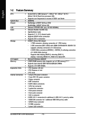
... Š 1 4-pin ATX 12V power connector Š 1 floppy connector Š 2 IDE connectors Š 4 SATA 3Gb/s connectors Š 1 CPU fan connector Š 1 system fan connector Š 1 front panel connector Š 1 front audio connector Š 1 CD In connector Š ...CPU Š Socket 939 for 1 additional IEEE1394 port by cables Š 1 IEEE1394 connector for AMD SempronTM / AlthlonTM 64 / AlthlonTM 64 FX / AlthlonTM 64 X2 Dual-Core processor (K8) Š Supports core frequencies in /out connector Š 1 COMA connector Š 1 power LED connector GA-K8N51PVMT...
... Š 1 4-pin ATX 12V power connector Š 1 floppy connector Š 2 IDE connectors Š 4 SATA 3Gb/s connectors Š 1 CPU fan connector Š 1 system fan connector Š 1 front panel connector Š 1 front audio connector Š 1 CD In connector Š ...CPU Š Socket 939 for 1 additional IEEE1394 port by cables Š 1 IEEE1394 connector for AMD SempronTM / AlthlonTM 64 / AlthlonTM 64 FX / AlthlonTM 64 X2 Dual-Core processor (K8) Š Supports core frequencies in /out connector Š 1 COMA connector Š 1 power LED connector GA-K8N51PVMT...

User Manual
Page 11
Hardware Installation For more detailed information please check at the FAQ section on GIGABYTE's website. (Note 4) EasyTune functions may vary depending on the CPU you install. For example, 4 GB of memory is reserved for system usage and therefore the actual ...Out) I/O Control Š W83627 chip Hardware Monitor Š System voltage detection Š CPU / system temperature detection Š CPU / system fan speed detection Š CPU warning temperature Š CPU /system fan failure warning Š CPU smart fan control (Note 3) BIOS Š 1 4Mbit flash ROM Š Use of...
Hardware Installation For more detailed information please check at the FAQ section on GIGABYTE's website. (Note 4) EasyTune functions may vary depending on the CPU you install. For example, 4 GB of memory is reserved for system usage and therefore the actual ...Out) I/O Control Š W83627 chip Hardware Monitor Š System voltage detection Š CPU / system temperature detection Š CPU / system fan speed detection Š CPU warning temperature Š CPU /system fan failure warning Š CPU smart fan control (Note 3) BIOS Š 1 4Mbit flash ROM Š Use of...
User Manual
Page 12
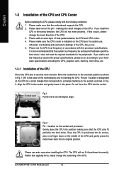
... on the socket and processor. English 1-3 Installation of the CPU and CPU Cooler Before installing the CPU, please comply with the processor specifications. Please make sure that corresponds to the socket and gently lower it does not meet the required standards for the peripherals. GA-K8N51PVMT-9-RH Motherboard - 12 - Please take note of heat paste...
... on the socket and processor. English 1-3 Installation of the CPU and CPU Cooler Before installing the CPU, please comply with the processor specifications. Please make sure that corresponds to the socket and gently lower it does not meet the required standards for the peripherals. GA-K8N51PVMT-9-RH Motherboard - 12 - Please take note of heat paste...
User Manual
Page 13
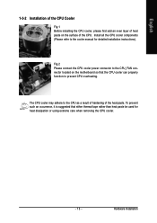
.... To prevent such an occurrence, it is suggested that the CPU cooler can properly function to the CPU as a result of hardening of the CPU. Hardware Installation The CPU cooler may adhere to prevent CPU overheating. English 1-3-2 Installation of the CPU Cooler Fig.1 Before installing the CPU cooler, please first add an even layer of heat paste...
.... To prevent such an occurrence, it is suggested that the CPU cooler can properly function to the CPU as a result of hardening of the CPU. Hardware Installation The CPU cooler may adhere to prevent CPU overheating. English 1-3-2 Installation of the CPU Cooler Fig.1 Before installing the CPU cooler, please first add an even layer of heat paste...

User Manual
Page 15
Due to CPU limitation, if you want to use memory modules of identical brand, size, chips, and speed. To enable Dual Channel mode with 4 memory modules, it is a ... Channel mode, we recommend installing them into DIMM sockets of the memory configurations below for Dual Channel memory configuration. 1. English Dual Channel Memory Configuration The GA-K8N51PVMT-9-RH supports the Dual Channel Technology. When the Dual Channel Technology is activated, the bandwidth of identical brand, size, chips, and speed), you must install...
Due to CPU limitation, if you want to use memory modules of identical brand, size, chips, and speed. To enable Dual Channel mode with 4 memory modules, it is a ... Channel mode, we recommend installing them into DIMM sockets of the memory configurations below for Dual Channel memory configuration. 1. English Dual Channel Memory Configuration The GA-K8N51PVMT-9-RH supports the Dual Channel Technology. When the Dual Channel Technology is activated, the bandwidth of identical brand, size, chips, and speed), you must install...

User Manual
Page 20
... 3.3V -12V GND PS_ON(soft On/Off) GND GND GND -5V +5V +5V +5V (Only for 24-pin ATX) GND(Only for 24-pin ATX) GA-K8N51PVMT-9-RH Motherboard - 20 - It is able to start . otherwise, please do not remove it. If the ATX_12V power connector is used that does not provide... be used (300W or greater). If a power supply is not connected, the system will not start . The ATX_12V power connector mainly supplies power to the CPU.
... 3.3V -12V GND PS_ON(soft On/Off) GND GND GND -5V +5V +5V +5V (Only for 24-pin ATX) GND(Only for 24-pin ATX) GA-K8N51PVMT-9-RH Motherboard - 20 - It is able to start . otherwise, please do not remove it. If the ATX_12V power connector is used that does not provide... be used (300W or greater). If a power supply is not connected, the system will not start . The ATX_12V power connector mainly supplies power to the CPU.

User Manual
Page 21
.... 34 33 2 1 - 21 - Please connect the red power connector wire to prevent system overheating and failure. The black connector wire is used to prevent CPU overheating and failure. 1 CPU_FAN 1 SYS_FAN Pin No. 1 2 3 Definition GND +12V Sense 5) FDD (FDD Connector) The FDD connector is the ground wire... (GND). Most coolers are : 360KB, 720KB, 1.2MB, 1.44MB and 2.88MB. Please remember to connect the power to the CPU fan to connect the FDD cable while the other end of FDD drives supported are designed with color-coded power connector wires. English 3/4) CPU_FAN /...
.... 34 33 2 1 - 21 - Please connect the red power connector wire to prevent system overheating and failure. The black connector wire is used to prevent CPU overheating and failure. 1 CPU_FAN 1 SYS_FAN Pin No. 1 2 3 Definition GND +12V Sense 5) FDD (FDD Connector) The FDD connector is the ground wire... (GND). Most coolers are : 360KB, 720KB, 1.2MB, 1.44MB and 2.88MB. Please remember to connect the power to the CPU fan to connect the FDD cable while the other end of FDD drives supported are designed with color-coded power connector wires. English 3/4) CPU_FAN /...

User Manual
Page 31
... Setup. „ Set User Password Change, set , or disable password. It allows you to limit access to the system and Setup, or just to control CPU clock and frequency ratio. „ Load Fail-Safe Defaults Fail-Safe Defaults indicates the value of the system parameters which the system would be in...
... Setup. „ Set User Password Change, set , or disable password. It allows you to limit access to the system and Setup, or just to control CPU clock and frequency ratio. „ Load Fail-Safe Defaults Fail-Safe Defaults indicates the value of the system parameters which the system would be in...
User Manual
Page 33
.... The value of the BIOS. BIOS Setup The two options are: Large/Auto(default:Auto) Capacity Capacity of base (or conventional) memory installed in the CPU's memory address map. Enter the appropriate option based on the motherboard. it will stop for all other errors. it will determine the amount of currently...
.... The value of the BIOS. BIOS Setup The two options are: Large/Auto(default:Auto) Capacity Capacity of base (or conventional) memory installed in the CPU's memory address map. Enter the appropriate option based on the motherboard. it will stop for all other errors. it will determine the amount of currently...

User Manual
Page 42
... Stop Warning Disabled Enabled Disable System/CPU fan stop warning function. (Default value) Enable System/CPU fan stop warning function. Monitor CPU temperature at 70oC / 158oF. CPU Warning Temp. 60oC / 140oF Monitor CPU temperature at 60oC / 140oF. 70oC / 158oF 80oC / 176oF 90oC / 194oF Disabled Monitor CPU temperature at 90oC / 194oF. GA-K8N51PVMT-9-RH Motherboard - 42 - English 2-6 PC Health...
... Stop Warning Disabled Enabled Disable System/CPU fan stop warning function. (Default value) Enable System/CPU fan stop warning function. Monitor CPU temperature at 70oC / 158oF. CPU Warning Temp. 60oC / 140oF Monitor CPU temperature at 60oC / 140oF. 70oC / 158oF 80oC / 176oF 90oC / 194oF Disabled Monitor CPU temperature at 90oC / 194oF. GA-K8N51PVMT-9-RH Motherboard - 42 - English 2-6 PC Health...

User Manual
Page 43
For more detailed information please check at different speed depending on CPU temperature. BIOS Setup English CPU Smart FAN Control (Note) Disabled Disable this function. (Default value) Enabled When this function is supported will run at the FAQ section on GIGABYTE's website. - 43 - Users can adjust the fan speed with Easy Tune based on their requirements. (Note) Whether the CPU Smart FAN Control function is enabled, CPU fan will depend on the CPU you install.
For more detailed information please check at different speed depending on CPU temperature. BIOS Setup English CPU Smart FAN Control (Note) Disabled Disable this function. (Default value) Enabled When this function is supported will run at the FAQ section on GIGABYTE's website. - 43 - Users can adjust the fan speed with Easy Tune based on their requirements. (Note) Whether the CPU Smart FAN Control function is enabled, CPU fan will depend on the CPU you install.

User Manual
Page 44
... the D-Sub port. (Default value) TV AUTO Set signal output from 200MHz to 300MHz. GA-K8N51PVMT-9-RH Motherboard - 44 - English 2-7 Frequency/Voltage Control CMOS Setup Utility-Copyright (C) 1984-2006 Award Software Frequency/Voltage Control CPU Frequency PCIE Clock K8 CPU Clock Ratio Display Output TV Mode Support Robust Graphics Booster [200.0] [100Mhz] [Default] [RGB...
... the D-Sub port. (Default value) TV AUTO Set signal output from 200MHz to 300MHz. GA-K8N51PVMT-9-RH Motherboard - 44 - English 2-7 Frequency/Voltage Control CMOS Setup Utility-Copyright (C) 1984-2006 Award Software Frequency/Voltage Control CPU Frequency PCIE Clock K8 CPU Clock Ratio Display Output TV Mode Support Robust Graphics Booster [200.0] [100Mhz] [Default] [RGB...

User Manual
Page 53
...cooling fan, 4) PC health for monitoring system status.(Note) User Interface Overview Button / Display 1. "Easy Mode" & "Advance Mode" 7. GIGABYTE Logo 10. and M.I .B.2 3. English Chapter 4 Appendix 4-1 Unique Software Utilities (Not all model support these Unique Software Utilities, please check ...4. Featuring several powerful yet easy to use tools such as 1) Overclocking for managing fan speed control of CPU frequency Shows the current functions status Log on to GIGABYTE website Display EasyTuneTM 5 Help file Quit or Minimize EasyTuneTM 5 software (Note) EasyTune 5 functions may vary...
...cooling fan, 4) PC health for monitoring system status.(Note) User Interface Overview Button / Display 1. "Easy Mode" & "Advance Mode" 7. GIGABYTE Logo 10. and M.I .B.2 3. English Chapter 4 Appendix 4-1 Unique Software Utilities (Not all model support these Unique Software Utilities, please check ...4. Featuring several powerful yet easy to use tools such as 1) Overclocking for managing fan speed control of CPU frequency Shows the current functions status Log on to GIGABYTE website Display EasyTuneTM 5 Help file Quit or Minimize EasyTuneTM 5 software (Note) EasyTune 5 functions may vary...


