Manual
Page 1
GA-H67MA-USB3-B3 LGA1155 socket motherboard for Intel® Core™ i7 processors/ Intel® Core™ i5 processors/Intel® Core™ i3 processors/ Intel® Pentium® processors/Intel® Celeron® processors User's Manual Rev. 1001 12ME-67MAB3B-1001R
GA-H67MA-USB3-B3 LGA1155 socket motherboard for Intel® Core™ i7 processors/ Intel® Core™ i5 processors/Intel® Core™ i3 processors/ Intel® Pentium® processors/Intel® Celeron® processors User's Manual Rev. 1001 12ME-67MAB3B-1001R
Manual
Page 3
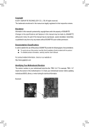
... respective owners. For product-related information, check on our website at: http://www.gigabyte.com Identifying Your Motherboard Revision The revision number on your motherboard revision before updating motherboard BIOS, drivers, or when looking for technical information. Disclaimer Information in this product, GIGABYTE provides the following types of documentations: For quick set-up of...
... respective owners. For product-related information, check on our website at: http://www.gigabyte.com Identifying Your Motherboard Revision The revision number on your motherboard revision before updating motherboard BIOS, drivers, or when looking for technical information. Disclaimer Information in this product, GIGABYTE provides the following types of documentations: For quick set-up of...
Manual
Page 4
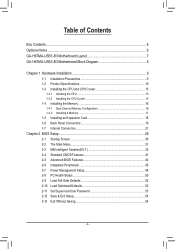
Table of Contents Box Contents...6 Optional Items...6 GA-H67MA-USB3-B3 Motherboard Layout 7 GA-H67MA-USB3-B3 Motherboard Block Diagram 8 Chapter 1 Hardware Installation 9 1-1 Installation Precautions 9 1-2 Product Specifications 10 1-3 Installing the CPU and CPU Cooler 13 1-3-1 Installing the CPU 13 1-3-2 Installing the CPU Cooler ...
Table of Contents Box Contents...6 Optional Items...6 GA-H67MA-USB3-B3 Motherboard Layout 7 GA-H67MA-USB3-B3 Motherboard Block Diagram 8 Chapter 1 Hardware Installation 9 1-1 Installation Precautions 9 1-2 Product Specifications 10 1-3 Installing the CPU and CPU Cooler 13 1-3-1 Installing the CPU 13 1-3-2 Installing the CPU Cooler ...
Manual
Page 6
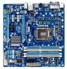
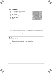
Optional Items 2-port USB 2.0 bracket (Part No. 12CR1-1UB030-5*R) 2-port SATA power cable (Part No. 12CF1-2SERPW-0*R) COM port cable (Part No. 12CF1-1CM001-3*R) - 6 - The box contents are for reference only. Box Contents GA-H67MA-USB3-B3 motherboard Motherboard driver disk User's Manual Quick Installation Guide Two SATA cables I/O Shield • The box contents above are subject to change without notice. • The motherboard image is for reference only and the actual items shall depend on the product package you obtain.
Optional Items 2-port USB 2.0 bracket (Part No. 12CR1-1UB030-5*R) 2-port SATA power cable (Part No. 12CF1-2SERPW-0*R) COM port cable (Part No. 12CF1-1CM001-3*R) - 6 - The box contents are for reference only. Box Contents GA-H67MA-USB3-B3 motherboard Motherboard driver disk User's Manual Quick Installation Guide Two SATA cables I/O Shield • The box contents above are subject to change without notice. • The motherboard image is for reference only and the actual items shall depend on the product package you obtain.
Manual
Page 7
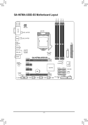
GA-H67MA-USB3-B3 Motherboard Layout DDR3_4 DDR3_2 DDR3_3 DDR3_1 KB_USB ATX_12V VGA_DVI LEVEL SHIFTER LGA1155 HDMI LEVEL SHIFTER OPTICAL ATX USB30_20 USB_LAN Etron EJ168 TPM CPU_FAN AUDIO Realtek RTL8111E PCIEX16 GA-H67MA-USB3-B3 PCIEX1_1 B_BIOS M_BIOS iTE IT8728 PCIEX1_2 CODEC PCIEX4 SPDIF_O F_AUDIO F_USB4 BAT F_USB3 F_USB2 Intel® H67 SATA3_0 SATA3_1 SYS_FAN SATA2_2 SATA2_3 SATA2_4 SATA2_5 F_PANEL COM CLR_CMOS F_USB1 - 7 -
GA-H67MA-USB3-B3 Motherboard Layout DDR3_4 DDR3_2 DDR3_3 DDR3_1 KB_USB ATX_12V VGA_DVI LEVEL SHIFTER LGA1155 HDMI LEVEL SHIFTER OPTICAL ATX USB30_20 USB_LAN Etron EJ168 TPM CPU_FAN AUDIO Realtek RTL8111E PCIEX16 GA-H67MA-USB3-B3 PCIEX1_1 B_BIOS M_BIOS iTE IT8728 PCIEX1_2 CODEC PCIEX4 SPDIF_O F_AUDIO F_USB4 BAT F_USB3 F_USB2 Intel® H67 SATA3_0 SATA3_1 SYS_FAN SATA2_2 SATA2_3 SATA2_4 SATA2_5 F_PANEL COM CLR_CMOS F_USB1 - 7 -
Manual
Page 8
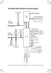
GA-H67MA-USB3-B3 Motherboard Block Diagram 1 PCI Express x16 CPU CLK+/- (100 MHz) LGA1155 CPU DDR3 1333/1066/800 MHz Dual Channel Memory DMI Interface FDI Interface PCIe CLK (...
GA-H67MA-USB3-B3 Motherboard Block Diagram 1 PCI Express x16 CPU CLK+/- (100 MHz) LGA1155 CPU DDR3 1333/1066/800 MHz Dual Channel Memory DMI Interface FDI Interface PCIe CLK (...
Manual
Page 9
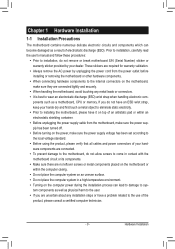
...ESD wrist strap, keep your hands dry and first touch a metal object to eliminate static electricity. •• Prior to installing the motherboard, please have a problem related to wear an electrostatic discharge (ESD) wrist strap when handling electronic com- These stickers are connected tightly ...and securely. •• When handling the motherboard, avoid touching any installation steps or have it on top of an antistatic pad or within the computer casing. •• ...
...ESD wrist strap, keep your hands dry and first touch a metal object to eliminate static electricity. •• Prior to installing the motherboard, please have a problem related to wear an electrostatic discharge (ESD) wrist strap when handling electronic com- These stickers are connected tightly ...and securely. •• When handling the motherboard, avoid touching any installation steps or have it on top of an antistatic pad or within the computer casing. •• ...
Manual
Page 12
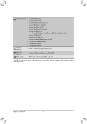
...ŠŠ Support for Xpress Install ŠŠ Support for Xpress Recovery2 ŠŠ Support for EasyTune * Available functions in EasyTune may differ by motherboard model. ŠŠ Support for Smart 6™ ŠŠ Support for Auto Green ŠŠ Support for eXtreme Hard Drive (X.H.D) ŠŠ... ŠŠ Support for Microsoft® Windows 7/Vista/XP Form Factor ŠŠ Micro ATX Form Factor; 24.4cm x 24.4cm * GIGABYTE reserves the right to make any changes to the product specifications and product-related information without prior notice.
...ŠŠ Support for Xpress Install ŠŠ Support for Xpress Recovery2 ŠŠ Support for EasyTune * Available functions in EasyTune may differ by motherboard model. ŠŠ Support for Smart 6™ ŠŠ Support for Auto Green ŠŠ Support for eXtreme Hard Drive (X.H.D) ŠŠ... ŠŠ Support for Microsoft® Windows 7/Vista/XP Form Factor ŠŠ Micro ATX Form Factor; 24.4cm x 24.4cm * GIGABYTE reserves the right to make any changes to the product specifications and product-related information without prior notice.
Manual
Page 13
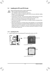
... following guidelines before installing the CPU to prevent hardware damage. •• Locate the pin one of the CPU. Locate the alignment keys on the motherboard CPU socket and the notches on the CPU - 13 - If you may occur. •• Set the CPU host frequency in accordance with the CPU... the standard requirements for the latest CPU support list.) •• Always turn on the computer if the CPU cooler is not recommended that the motherboard supports the CPU. (Go to GIGABYTE's website for the peripherals. It is not installed, otherwise overheating and dam-
... following guidelines before installing the CPU to prevent hardware damage. •• Locate the pin one of the CPU. Locate the alignment keys on the motherboard CPU socket and the notches on the CPU - 13 - If you may occur. •• Set the CPU host frequency in accordance with the CPU... the standard requirements for the latest CPU support list.) •• Always turn on the computer if the CPU cooler is not recommended that the motherboard supports the CPU. (Go to GIGABYTE's website for the peripherals. It is not installed, otherwise overheating and dam-

Manual
Page 14
... CPU with the socket alignment keys) and gently insert the CPU into position. Hardware Installation - 14 - Step 5: Push the CPU socket lever back into the motherboard CPU socket. Before installing the CPU, make sure the front end of the CPU socket (or you may align the CPU notches with your thumb...
... CPU with the socket alignment keys) and gently insert the CPU into position. Hardware Installation - 14 - Step 5: Push the CPU socket lever back into the motherboard CPU socket. Before installing the CPU, make sure the front end of the CPU socket (or you may align the CPU notches with your thumb...

Manual
Page 15
... Pin The Top of Female Push Pin Female Push Pin Step 1: Apply an even and thin layer of thermal grease on the surface of the motherboard. Step 4: You should hear a "click" when pushing down on the push pins diagonally. Use extreme care when removing the CPU cooler because the thermal... above shows, the installation is to install.) Step 3: Place the cooler atop the CPU, aligning the four push pins through the pin holes on the motherboard. Check that the Male and Female push pins are joined closely. (Refer to the CPU. Step 6: Finally, attach the power connector of arrow is...
... Pin The Top of Female Push Pin Female Push Pin Step 1: Apply an even and thin layer of thermal grease on the surface of the motherboard. Step 4: You should hear a "click" when pushing down on the push pins diagonally. Use extreme care when removing the CPU cooler because the thermal... above shows, the installation is to install.) Step 3: Place the cooler atop the CPU, aligning the four push pins through the pin holes on the motherboard. Check that the Male and Female push pins are joined closely. (Refer to the CPU. Step 6: Finally, attach the power connector of arrow is...
Manual
Page 16
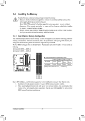
... modules.) •• Always turn off the computer and unplug the power cord from the power outlet before installing the memory to GIGABYTE's website for optimum performance. It is installed, the BIOS will double the original memory bandwidth. If you begin to insert the memory..., switch the direction. 1-4-1 Dual Channel Memory Configuration This motherboard provides four DDR3 memory sockets and supports Dual Channel Technology. After the memory is recommended that the motherboard supports the memory. DS/SS DDR3_3 - DS/SS DS/SS (SS=Single-Sided,...
... modules.) •• Always turn off the computer and unplug the power cord from the power outlet before installing the memory to GIGABYTE's website for optimum performance. It is installed, the BIOS will double the original memory bandwidth. If you begin to insert the memory..., switch the direction. 1-4-1 Dual Channel Memory Configuration This motherboard provides four DDR3 memory sockets and supports Dual Channel Technology. After the memory is recommended that the motherboard supports the memory. DS/SS DDR3_3 - DS/SS DS/SS (SS=Single-Sided,...
Manual
Page 17
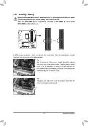
... DIMM A DDR3 memory module has a notch, so it vertically into place when the memory module is securely inserted. - 17 - Place the memory module on this motherboard. Step 2: The clips at both ends of the memory module. Step 1: Note the orientation of the socket will snap into the memory socket. Follow the...
... DIMM A DDR3 memory module has a notch, so it vertically into place when the memory module is securely inserted. - 17 - Place the memory module on this motherboard. Step 2: The clips at both ends of the memory module. Step 1: Note the orientation of the socket will snap into the memory socket. Follow the...
Manual
Page 18
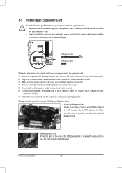
... the card are completely inserted into the PCI Express slot. If necessary, go to BIOS Setup to install an expansion card: • Make sure the motherboard supports the expansion card.
... the card are completely inserted into the PCI Express slot. If necessary, go to BIOS Setup to install an expansion card: • Make sure the motherboard supports the expansion card.
Manual
Page 20
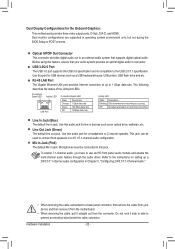
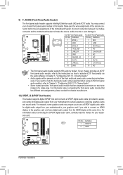
...Optical S/PDIF Out Connector This connector provides digital audio out to an external audio system that your device and then remove it from the motherboard. •• When removing the cable, pull it side to side to a back panel connector, first remove the cable from your ...State Description Blinking Data transmission or receiving is occurring Off No data transmission or receiving is compatible to this port for the Onboard Graphics: This motherboard provides three video output ports: D-Sub, DVI-D, and HDMI. Use this jack. Line Out Jack (Green) The default line out jack....
...Optical S/PDIF Out Connector This connector provides digital audio out to an external audio system that your device and then remove it from the motherboard. •• When removing the cable, pull it side to side to a back panel connector, first remove the cable from your ...State Description Blinking Data transmission or receiving is occurring Off No data transmission or receiving is compatible to this port for the Onboard Graphics: This motherboard provides three video output ports: D-Sub, DVI-D, and HDMI. Use this jack. Line Out Jack (Green) The default line out jack....
Manual
Page 21
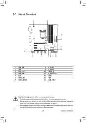
... 3) CPU_FAN 4) SYS_FAN 5) BAT 6) SATA3_0/1 7) SATA2_2/3/4/5 8) F_PANEL 9) F_AUDIO 10) SPDIF_O 11) F_USB1/2/3/4 12) COM 13) TPM 14) CLR_CMOS Read the following guidelines before turning on the motherboard. - 21 - Hardware Installation Unplug the power cord from the power outlet to prevent damage to the devices. •• After installing the device and before...
... 3) CPU_FAN 4) SYS_FAN 5) BAT 6) SATA3_0/1 7) SATA2_2/3/4/5 8) F_PANEL 9) F_AUDIO 10) SPDIF_O 11) F_USB1/2/3/4 12) COM 13) TPM 14) CLR_CMOS Read the following guidelines before turning on the motherboard. - 21 - Hardware Installation Unplug the power cord from the power outlet to prevent damage to the devices. •• After installing the device and before...
Manual
Page 22
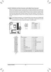
...-pin ATX) GND (Only for 2x12-pin ATX) Hardware Installation - 22 - To meet expansion requirements, it is turned off and all the components on the motherboard. The 12V power connector mainly supplies power to the power connector in the correct orientation. If a power supply is not connected, the computer will not...
...-pin ATX) GND (Only for 2x12-pin ATX) Hardware Installation - 22 - To meet expansion requirements, it is turned off and all the components on the motherboard. The 12V power connector mainly supplies power to the power connector in the correct orientation. If a power supply is not connected, the computer will not...

Manual
Page 23
...to touch the positive and negative terminals of purchase or local dealer if you are not configuration jumper blocks. 3/4) CPU_FAN/SYS_FAN (Fan Headers) The motherboard has a 4-pin CPU fan header (CPU_FAN), a 4-pin system fan header (SYS_FAN). You may hang. •• These fan headers are... not able to connect it is replaced with fan speed control design. The motherboard supports CPU fan speed control, which requires the use a metal object like a screwdriver to keep the values (such as BIOS configurations, date...
...to touch the positive and negative terminals of purchase or local dealer if you are not configuration jumper blocks. 3/4) CPU_FAN/SYS_FAN (Fan Headers) The motherboard has a 4-pin CPU fan header (CPU_FAN), a 4-pin system fan header (SYS_FAN). You may hang. •• These fan headers are... not able to connect it is replaced with fan speed control design. The motherboard supports CPU fan speed control, which requires the use a metal object like a screwdriver to keep the values (such as BIOS configurations, date...
Manual
Page 26
... to work or even damage it. For information about connecting the front panel audio module that has separated connectors on both of the motherboard header. 9) F_AUDIO (Front Panel Audio Header) The front panel audio header supports Intel High Definition audio (HD) and AC'97 ...audio. You may require you to certain expansion cards like graphics cards and sound cards. Incorrect connection between the module connector and the motherboard header will be present on each wire instead of a single plug. Definition 1F_PANMELI(CN2H_)L 2 GND Pin No. 1 2 Definition MIC GND F_PANEL ...
... to work or even damage it. For information about connecting the front panel audio module that has separated connectors on both of the motherboard header. 9) F_AUDIO (Front Panel Audio Header) The front panel audio header supports Intel High Definition audio (HD) and AC'97 ...audio. You may require you to certain expansion cards like graphics cards and sound cards. Incorrect connection between the module connector and the motherboard header will be present on each wire instead of a single plug. Definition 1F_PANMELI(CN2H_)L 2 GND Pin No. 1 2 Definition MIC GND F_PANEL ...
Manual
Page 28
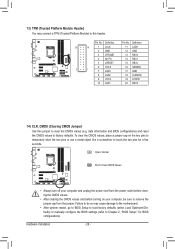
... turn off your computer, be sure to clear the CMOS values (e.g. TPM w/housing 13) TPM (Trusted Platform Module Header) You may cause damage to the motherboard. •• After system restart, go to BIOS Setup to load factory defaults (select Load Optimized Defaults) or manually configure the BIOS settings (refer to...
... turn off your computer, be sure to clear the CMOS values (e.g. TPM w/housing 13) TPM (Trusted Platform Module Header) You may cause damage to the motherboard. •• After system restart, go to BIOS Setup to load factory defaults (select Load Optimized Defaults) or manually configure the BIOS settings (refer to...


