Manual
Page 1
GA-H67MA-D2H LGA1155 socket motherboard for Intel® Core™ i7 processors/ Intel® Core™ i5 processors/Intel® Core™ i3 processors/ Intel® Pentium® processors/Intel® Celeron® processors User's Manual Rev. 1002 12ME-H67D2H-1002R
GA-H67MA-D2H LGA1155 socket motherboard for Intel® Core™ i7 processors/ Intel® Core™ i5 processors/Intel® Core™ i3 processors/ Intel® Pentium® processors/Intel® Celeron® processors User's Manual Rev. 1002 12ME-H67D2H-1002R

Manual
Page 3
... without prior notice. For example, "REV: 1.0" means the revision of the motherboard is the property of this : "REV: X.X." The trademarks mentioned in the use of GIGABYTE. No part of the product, read the Quick Installation Guide included with the product... on our website at: http://www.gigabyte.com Identifying Your Motherboard Revision The revision number on your motherboard revision before updating motherboard BIOS, drivers, or when looking for technical information. Example: Check your motherboard looks like this product, GIGABYTE provides the following types of documentations:...
... without prior notice. For example, "REV: 1.0" means the revision of the motherboard is the property of this : "REV: X.X." The trademarks mentioned in the use of GIGABYTE. No part of the product, read the Quick Installation Guide included with the product... on our website at: http://www.gigabyte.com Identifying Your Motherboard Revision The revision number on your motherboard revision before updating motherboard BIOS, drivers, or when looking for technical information. Example: Check your motherboard looks like this product, GIGABYTE provides the following types of documentations:...
Manual
Page 4
Table of Contents Box Contents...6 Optional Items...6 GA-H67MA-D2H Motherboard Layout 7 GA-H67MA-D2H Motherboard Block Diagram 8 Chapter 1 Hardware Installation 9 1-1 Installation Precautions 9 1-2 Product Specifications 10 1-3 Installing the CPU and CPU Cooler 13 1-3-1 Installing the CPU 13 1-3-2 Installing the CPU Cooler ...
Table of Contents Box Contents...6 Optional Items...6 GA-H67MA-D2H Motherboard Layout 7 GA-H67MA-D2H Motherboard Block Diagram 8 Chapter 1 Hardware Installation 9 1-1 Installation Precautions 9 1-2 Product Specifications 10 1-3 Installing the CPU and CPU Cooler 13 1-3-1 Installing the CPU 13 1-3-2 Installing the CPU Cooler ...
Manual
Page 6
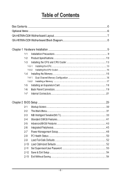
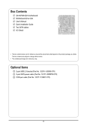
The box contents are for reference only. Optional Items 2-port USB 2.0 bracket (Part No. 12CR1-1UB030-5*R) 2-port SATA power cable (Part No. 12CF1-2SERPW-0*R) COM port cable (Part No. 12CF1-1CM001-3*R) - 6 - Box Contents GA-H67MA-D2H motherboard Motherboard driver disk User's Manual Quick Installation Guide Two SATA cables I/O Shield • The box contents above are subject to change without notice. • The motherboard image is for reference only and the actual items shall depend on the product package you obtain.
The box contents are for reference only. Optional Items 2-port USB 2.0 bracket (Part No. 12CR1-1UB030-5*R) 2-port SATA power cable (Part No. 12CF1-2SERPW-0*R) COM port cable (Part No. 12CF1-1CM001-3*R) - 6 - Box Contents GA-H67MA-D2H motherboard Motherboard driver disk User's Manual Quick Installation Guide Two SATA cables I/O Shield • The box contents above are subject to change without notice. • The motherboard image is for reference only and the actual items shall depend on the product package you obtain.
Manual
Page 7
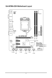
GA-H67MA-D2H Motherboard Layout KB_USB ATX_12V VGA_DVI LGA1155 PHASE LED HDMI_SPDIF USB_ESATA ATX USB30_LAN Renesas D720200 AUDIO CPU_FAN PCIEX16 GA-H67MA-D2H B_BIOS M_BIOS DDR3_1 DDR3_2 Realtek RTL8111E PCIEX1_1 PCIEX1_2 SYS_FAN CODEC PCIEX4 SPDIF_O BAT iTE IT8728 CLR_CMOS Intel® H67 SATA3_0 SATA3_1 SATA2_2 F_PANEL SATA2_3 SATA2_4 F_AUDIO COM F_USB4 F_USB2 F_USB3 F_USB1 - 7 -
GA-H67MA-D2H Motherboard Layout KB_USB ATX_12V VGA_DVI LGA1155 PHASE LED HDMI_SPDIF USB_ESATA ATX USB30_LAN Renesas D720200 AUDIO CPU_FAN PCIEX16 GA-H67MA-D2H B_BIOS M_BIOS DDR3_1 DDR3_2 Realtek RTL8111E PCIEX1_1 PCIEX1_2 SYS_FAN CODEC PCIEX4 SPDIF_O BAT iTE IT8728 CLR_CMOS Intel® H67 SATA3_0 SATA3_1 SATA2_2 F_PANEL SATA2_3 SATA2_4 F_AUDIO COM F_USB4 F_USB2 F_USB3 F_USB1 - 7 -
Manual
Page 8
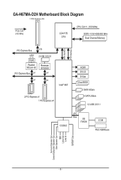
GA-H67MA-D2H Motherboard Block Diagram 1 PCI Express x16 PCIe CLK (100 MHz) LGA1155 CPU CPU CLK+/- (100 MHz) DDR3 1333/1066/800 MHz Dual Channel Memory PCI Express Bus x16 LAN 2 USB 3.0/2.0 RJ45 Realtek RTL8111E Renesas D720200 PCI Express Bus x1 x1 x1 x4 Intel® H67 2 PCI Express x1 1 PCI Express x4 DMI Interface FDI Interface HDMI DVI-D D-Sub Dual BIOS 2 SATA 6Gb/s 4 SATA 3Gb/s 12 USB 2.0/1.1 CODEC LPC Bus iTE IT8728 COM PS/2 KB/Mouse Surround Speaker Out Center/Subwoofer Speaker Out Side Speaker Out MIC Line Out Line In S/PDIF Out - 8 -
GA-H67MA-D2H Motherboard Block Diagram 1 PCI Express x16 PCIe CLK (100 MHz) LGA1155 CPU CPU CLK+/- (100 MHz) DDR3 1333/1066/800 MHz Dual Channel Memory PCI Express Bus x16 LAN 2 USB 3.0/2.0 RJ45 Realtek RTL8111E Renesas D720200 PCI Express Bus x1 x1 x1 x4 Intel® H67 2 PCI Express x1 1 PCI Express x4 DMI Interface FDI Interface HDMI DVI-D D-Sub Dual BIOS 2 SATA 6Gb/s 4 SATA 3Gb/s 12 USB 2.0/1.1 CODEC LPC Bus iTE IT8728 COM PS/2 KB/Mouse Surround Speaker Out Center/Subwoofer Speaker Out Side Speaker Out MIC Line Out Line In S/PDIF Out - 8 -

Manual
Page 9
... in a high-temperature environment. • Turning on the power, make sure they are connected tightly and securely. • When handling the motherboard, avoid touching any installation steps or have it on top of an antistatic pad or within an electrostatic shielding container. • Before unplugging the... power supply cable from the motherboard, make sure the power supply has been turned off. • Before turning on the computer power during the installation process can become ...
... in a high-temperature environment. • Turning on the power, make sure they are connected tightly and securely. • When handling the motherboard, avoid touching any installation steps or have it on top of an antistatic pad or within an electrostatic shielding container. • Before unplugging the... power supply cable from the motherboard, make sure the power supply has been turned off. • Before turning on the computer power during the installation process can become ...
Manual
Page 12
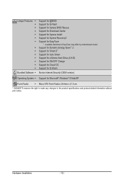
... Charge Support for Cloud OC Support for Q-Share Norton Internet Security (OEM version) Operating System w Support for EasyTune * Available functions in EasyTune may differ by motherboard model. Unique Features w w w w w w w w w w w w w w Bundled Software w Support for @BIOS Support for Q-Flash Support for...® 7/Vista/XP Form Factor w Micro ATX Form Factor; 24.4cm x 21.1cm * GIGABYTE reserves the right to make any changes to the product specifications and product-related information without prior notice.
... Charge Support for Cloud OC Support for Q-Share Norton Internet Security (OEM version) Operating System w Support for EasyTune * Available functions in EasyTune may differ by motherboard model. Unique Features w w w w w w w w w w w w w w Bundled Software w Support for @BIOS Support for Q-Flash Support for...® 7/Vista/XP Form Factor w Micro ATX Form Factor; 24.4cm x 21.1cm * GIGABYTE reserves the right to make any changes to the product specifications and product-related information without prior notice.

Manual
Page 13
...Triangle Pin One Marking on the CPU. Hardware Installation It is not installed, otherwise overheating and dam- Locate the alignment keys on the motherboard CPU socket and the notches on the CPU - 13 - The CPU cannot be set the frequency beyond hardware specifications since it does ...for the latest CPU support list.) • Always turn on the computer if the CPU cooler is not recommended that the motherboard supports the CPU. (Go to GIGABYTE's website for the peripherals. 1-3 Installing the CPU and CPU Cooler Read the following guidelines before installing the CPU to prevent...
...Triangle Pin One Marking on the CPU. Hardware Installation It is not installed, otherwise overheating and dam- Locate the alignment keys on the motherboard CPU socket and the notches on the CPU - 13 - The CPU cannot be set the frequency beyond hardware specifications since it does ...for the latest CPU support list.) • Always turn on the computer if the CPU cooler is not recommended that the motherboard supports the CPU. (Go to GIGABYTE's website for the peripherals. 1-3 Installing the CPU and CPU Cooler Read the following guidelines before installing the CPU to prevent...

Manual
Page 14
... away from the power outlet to prevent damage to the CPU. When replacing the load plate, make sure to correctly install the CPU into the motherboard CPU socket. Step 1: Gently press the CPU socket lever handle down on the rear grip of the socket cover and use the other to the...
... away from the power outlet to prevent damage to the CPU. When replacing the load plate, make sure to correctly install the CPU into the motherboard CPU socket. Step 1: Gently press the CPU socket lever handle down on the rear grip of the socket cover and use the other to the...

Manual
Page 15
... Pin The Top of Female Push Pin Female Push Pin Step 1: Apply an even and thin layer of thermal grease on the surface of the motherboard. Step 6: Finally, attach the power connector of arrow is to remove the cooler, on the contrary, is to install.) Step 3: Place the cooler atop the... CPU, aligning the four push pins through the pin holes on the motherboard. Push down each push pin. Check that the Male and Female push pins are joined closely. (Refer to your CPU cooler installation manual for instructions...
... Pin The Top of Female Push Pin Female Push Pin Step 1: Apply an even and thin layer of thermal grease on the surface of the motherboard. Step 6: Finally, attach the power connector of arrow is to remove the cooler, on the contrary, is to install.) Step 3: Place the cooler atop the... CPU, aligning the four push pins through the pin holes on the motherboard. Push down each push pin. Check that the Male and Female push pins are joined closely. (Refer to your CPU cooler installation manual for instructions...

Manual
Page 16
... socket as following: Channel 0: DDR3_1 Channel 1: DDR3_2 DDR3_1 DDR3_2 Due to GIGABYTE's website for optimum performance. When enabling Dual Channel mode with two memory modules, it is recommended that the motherboard supports the memory. A memory module can be enabled if only one DDR3 ...will double the original memory bandwidth. If you begin to insert the memory, switch the direction. 1-4-1 Dual Channel Memory Configuration This motherboard provides two DDR3 memory sockets and supports Dual Channel Technology. The two DDR3 memory sockets are unable to install the memory: •...
... socket as following: Channel 0: DDR3_1 Channel 1: DDR3_2 DDR3_1 DDR3_2 Due to GIGABYTE's website for optimum performance. When enabling Dual Channel mode with two memory modules, it is recommended that the motherboard supports the memory. A memory module can be enabled if only one DDR3 ...will double the original memory bandwidth. If you begin to insert the memory, switch the direction. 1-4-1 Dual Channel Memory Configuration This motherboard provides two DDR3 memory sockets and supports Dual Channel Technology. The two DDR3 memory sockets are unable to install the memory: •...

Manual
Page 17
... the memory sockets. Spread the retaining clips at both ends of the socket will snap into the memory socket. Place the memory module on this motherboard. Hardware Installation Notch DDR3 DIMM A DDR3 memory module has a notch, so it vertically into place when the memory module is securely inserted. - 17 - Step 2: The...
... the memory sockets. Spread the retaining clips at both ends of the socket will snap into the memory socket. Place the memory module on this motherboard. Hardware Installation Notch DDR3 DIMM A DDR3 memory module has a notch, so it vertically into place when the memory module is securely inserted. - 17 - Step 2: The...
Manual
Page 18
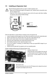
... turn off the computer and unplug the power cord from the power outlet before you begin to install an expansion card: • Make sure the motherboard supports the expansion card. PCI Express x1 Slot PCI Express x16 Slot Follow the steps below to correctly install your expansion card in your operating...
... turn off the computer and unplug the power cord from the power outlet before you begin to install an expansion card: • Make sure the motherboard supports the expansion card. PCI Express x1 Slot PCI Express x16 Slot Follow the steps below to correctly install your expansion card in your operating...
Manual
Page 20
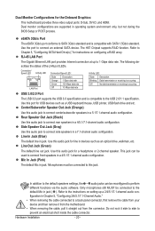
...up a 2/4/5.1/7.1-channel audio configuration in a 4/5.1/7.1-channel audio configuration. Center/Subwoofer Speaker Out Jack (Orange) Use this audio jack for the Onboard Graphics: This motherboard provides three video output ports: D-Sub, DVI-D, and HDMI. Line Out Jack (Green) The default line out jack. This jack can be connected ... jacks can be connected to Chapter 5, "Configuring SATA Hard Drive(s)," for line in jack. Do not rock it straight out from the motherboard. • When removing the cable, pull it side to side to 1 Gbps data rate. Hardware Installation - 20 -
...up a 2/4/5.1/7.1-channel audio configuration in a 4/5.1/7.1-channel audio configuration. Center/Subwoofer Speaker Out Jack (Orange) Use this audio jack for the Onboard Graphics: This motherboard provides three video output ports: D-Sub, DVI-D, and HDMI. Line Out Jack (Green) The default line out jack. This jack can be connected ... jacks can be connected to Chapter 5, "Configuring SATA Hard Drive(s)," for line in jack. Do not rock it straight out from the motherboard. • When removing the cable, pull it side to side to 1 Gbps data rate. Hardware Installation - 20 -

Manual
Page 21
... devices and your devices are compliant with the connectors you wish to connect. • Before installing the devices, be sure to the connector on the motherboard. - 21 -
... devices and your devices are compliant with the connectors you wish to connect. • Before installing the devices, be sure to the connector on the motherboard. - 21 -

Manual
Page 22
... the power supply is not connected, the computer will not start. If the 12V power connector is turned off and all the components on the motherboard. Connect the power supply cable to the CPU. The power connector possesses a foolproof design.
... the power supply is not connected, the computer will not start. If the 12V power connector is turned off and all the components on the motherboard. Connect the power supply cable to the CPU. The power connector possesses a foolproof design.

Manual
Page 23
... fan with the SATA2_2/3/4 and eSATA connectors . (Note) Refer to the CPU or the system may vary depending on the devices being connected. - 23 - The motherboard supports CPU fan speed control, which requires the use of hard drives does not have to be an even number. • A RAID 5 configuration requires at... the L-shaped end of the RAID set is built across the SATA 6Gb/s and SATA 3Gb/s channels, the system perfor- 3/4) CPU_FAN/SYS_FAN (Fan Headers) The motherboard has a 4-pin CPU fan header (CPU_FAN) and a 4-pin (SYS_FAN) system fan.
... fan with the SATA2_2/3/4 and eSATA connectors . (Note) Refer to the CPU or the system may vary depending on the devices being connected. - 23 - The motherboard supports CPU fan speed control, which requires the use of hard drives does not have to be an even number. • A RAID 5 configuration requires at... the L-shaped end of the RAID set is built across the SATA 6Gb/s and SATA 3Gb/s channels, the system perfor- 3/4) CPU_FAN/SYS_FAN (Fan Headers) The motherboard has a 4-pin CPU fan header (CPU_FAN) and a 4-pin (SYS_FAN) system fan.

Manual
Page 26
... certain expansion cards like graphics cards and sound cards. Incorrect connection between the module connector and the motherboard header will be present on both of the front and back panel audio connections simultaneously. If your graphics card if you want to mute the ... the pin assignments of a single plug. For information about connecting the S/PDIF digital audio cable, carefully read the manual for digital audio output from your motherboard to your chassis provides an AC'97 front panel audio module, refer to the instructions on each wire instead of the...
... certain expansion cards like graphics cards and sound cards. Incorrect connection between the module connector and the motherboard header will be present on both of the front and back panel audio connections simultaneously. If your graphics card if you want to mute the ... the pin assignments of a single plug. For information about connecting the S/PDIF digital audio cable, carefully read the manual for digital audio output from your motherboard to your chassis provides an AC'97 front panel audio module, refer to the instructions on each wire instead of the...
Manual
Page 28
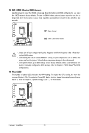
... the jumper. To enable the Phase LED display function, please first enable Dynamic Energy Saver™ 2. Failure to do so may cause damage to the motherboard. • After system restart, go to BIOS Setup to load factory defaults (select Load Optimized Defaults) or manually configure the BIOS settings (refer to Chapter...
... the jumper. To enable the Phase LED display function, please first enable Dynamic Energy Saver™ 2. Failure to do so may cause damage to the motherboard. • After system restart, go to BIOS Setup to load factory defaults (select Load Optimized Defaults) or manually configure the BIOS settings (refer to Chapter...


