Manual
Page 3
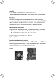
... written permission. For product-related information, check on our website at: http://www.gigabyte.com Identifying Your Motherboard Revision The revision number on your motherboard revision before updating motherboard BIOS, drivers, or when looking for technical information. For example, "REV: 1.0" means the revision of the product, read ... in any form or by any means without prior notice. Example: Documentation Classifications In order to assist in this product, GIGABYTE provides the following types of documentations: For quick set-up of the motherboard is the property of...
... written permission. For product-related information, check on our website at: http://www.gigabyte.com Identifying Your Motherboard Revision The revision number on your motherboard revision before updating motherboard BIOS, drivers, or when looking for technical information. For example, "REV: 1.0" means the revision of the product, read ... in any form or by any means without prior notice. Example: Documentation Classifications In order to assist in this product, GIGABYTE provides the following types of documentations: For quick set-up of the motherboard is the property of...
Manual
Page 4
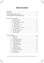
Table of Contents Box Contents...6 Optional Items...6 GA-H67A-USB3-B3 Motherboard Layout 7 GA-H67A-USB3-B3 Motherboard Block Diagram 8 Chapter 1 Hardware Installation 9 1-1 Installation Precautions 9 1-2 Product Specifications 10 1-3 Installing the CPU and CPU ... an Expansion Card 18 1-6 Back Panel Connectors 19 1-7 Internal Connectors 21 Chapter 2 BIOS Setup 29 2-1 Startup Screen 30 2-2 The Main Menu 31 2-3 MB Intelligent Tweaker(M.I.T 33 2-4 Standard CMOS Features 41 2-5 Advanced BIOS Features 43 2-6 Integrated Peripherals 45 2-7 Power Management Setup 48 2-8 PC Health Status ...
Table of Contents Box Contents...6 Optional Items...6 GA-H67A-USB3-B3 Motherboard Layout 7 GA-H67A-USB3-B3 Motherboard Block Diagram 8 Chapter 1 Hardware Installation 9 1-1 Installation Precautions 9 1-2 Product Specifications 10 1-3 Installing the CPU and CPU ... an Expansion Card 18 1-6 Back Panel Connectors 19 1-7 Internal Connectors 21 Chapter 2 BIOS Setup 29 2-1 Startup Screen 30 2-2 The Main Menu 31 2-3 MB Intelligent Tweaker(M.I.T 33 2-4 Standard CMOS Features 41 2-5 Advanced BIOS Features 43 2-6 Integrated Peripherals 45 2-7 Power Management Setup 48 2-8 PC Health Status ...
Manual
Page 5
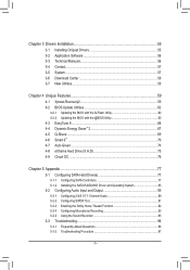
... 56 3-4 Contact...57 3-5 System...57 3-6 Download Center 58 3-7 New Utilities...58 Chapter 4 Unique Features 59 4-1 Xpress Recovery2 59 4-2 BIOS Update Utilities 62 4-2-1 Updating the BIOS with the Q-Flash Utility 62 4-2-2 Updating the BIOS with the @BIOS Utility 65 4-3 EasyTune 6...66 4-4 Dynamic Energy Saver™ 2 67 4-5 Q-Share...69 4-6 Smart 6™ ...70 4-7 Auto Green...74 4-8 eXtreme...
... 56 3-4 Contact...57 3-5 System...57 3-6 Download Center 58 3-7 New Utilities...58 Chapter 4 Unique Features 59 4-1 Xpress Recovery2 59 4-2 BIOS Update Utilities 62 4-2-1 Updating the BIOS with the Q-Flash Utility 62 4-2-2 Updating the BIOS with the @BIOS Utility 65 4-3 EasyTune 6...66 4-4 Dynamic Energy Saver™ 2 67 4-5 Q-Share...69 4-6 Smart 6™ ...70 4-7 Auto Green...74 4-8 eXtreme...
Manual
Page 8
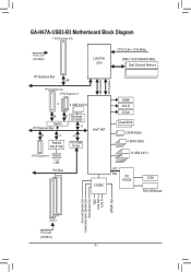
GA-H67A-USB3-B3 Motherboard Block Diagram 1 PCI Express x16 PCIe CLK (100 MHz) LGA1155 CPU CPU CLK+/- (100 MHz) DDR3 1333/1066/800 MHz Dual Channel Memory PCI ... x1 Realtek RTL8111E iTE IT8892 Bridge 1 PCI Express x1 RJ45 LAN PCI Bus Intel® H67 CODEC DMI Interface FDI Interface HDMI DVI-D D-Sub Dual BIOS 2 SATA 6Gb/s 4 SATA 3Gb/s 12 USB 2.0/1.1 LPC Bus iTE IT8728 COM PS/2 KB/Mouse Surround Speaker Out Center/Subwoofer Speaker Out Side Speaker Out MIC...
GA-H67A-USB3-B3 Motherboard Block Diagram 1 PCI Express x16 PCIe CLK (100 MHz) LGA1155 CPU CPU CLK+/- (100 MHz) DDR3 1333/1066/800 MHz Dual Channel Memory PCI ... x1 Realtek RTL8111E iTE IT8892 Bridge 1 PCI Express x1 RJ45 LAN PCI Bus Intel® H67 CODEC DMI Interface FDI Interface HDMI DVI-D D-Sub Dual BIOS 2 SATA 6Gb/s 4 SATA 3Gb/s 12 USB 2.0/1.1 LPC Bus iTE IT8728 COM PS/2 KB/Mouse Surround Speaker Out Center/Subwoofer Speaker Out Side Speaker Out MIC...
Manual
Page 12
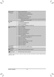
...flash ŠŠ Use of licensed AWARD BIOS ŠŠ Support for DualBIOS™ ŠŠ PnP 1.0a, DMI 2.0, SM BIOS 2.4, ACPI 1.0b Unique Features ŠŠ Support for @BIOS ŠŠ Support for Q-Flash ŠŠ Support for Xpress BIOS Rescue ŠŠ Support for Download Center...;Š Support for Microsoft® Windows 7/Vista/XP Form Factor ŠŠ ATX Form Factor; 30.5cm x 24.4cm * GIGABYTE reserves the right to make any changes to the product specifications and product-related information without prior notice. Hardware ŠŠ System voltage...
...flash ŠŠ Use of licensed AWARD BIOS ŠŠ Support for DualBIOS™ ŠŠ PnP 1.0a, DMI 2.0, SM BIOS 2.4, ACPI 1.0b Unique Features ŠŠ Support for @BIOS ŠŠ Support for Q-Flash ŠŠ Support for Xpress BIOS Rescue ŠŠ Support for Download Center...;Š Support for Microsoft® Windows 7/Vista/XP Form Factor ŠŠ ATX Form Factor; 30.5cm x 24.4cm * GIGABYTE reserves the right to make any changes to the product specifications and product-related information without prior notice. Hardware ŠŠ System voltage...
Manual
Page 16
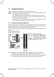
.... • Memory modules have a foolproof design. When enabling Dual Channel mode with two or four memory modules, it is installed, the BIOS will double the original memory bandwidth. If you begin to install the memory: • Make sure that memory of the memory. DS/SS... Channel memory mode will automatically detect the specifications and capacity of the same capacity, brand, speed, and chips be used . (Go to GIGABYTE's website for optimum performance. The four DDR3 memory sockets are unable to insert the memory, switch the direction. 1-4-1 Dual Channel Memory Configuration This...
.... • Memory modules have a foolproof design. When enabling Dual Channel mode with two or four memory modules, it is installed, the BIOS will double the original memory bandwidth. If you begin to install the memory: • Make sure that memory of the memory. DS/SS... Channel memory mode will automatically detect the specifications and capacity of the same capacity, brand, speed, and chips be used . (Go to GIGABYTE's website for optimum performance. The four DDR3 memory sockets are unable to insert the memory, switch the direction. 1-4-1 Dual Channel Memory Configuration This...
Manual
Page 18
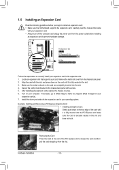
... card(s). 7. Align the card with your computer. Hardware Installation - 18 - Remove the metal slot cover from the slot. If necessary, go to BIOS Setup to make any required BIOS changes for your operating system. Secure the card's metal bracket to the chassis back panel with the expansion card in the slot and...
... card(s). 7. Align the card with your computer. Hardware Installation - 18 - Remove the metal slot cover from the slot. If necessary, go to BIOS Setup to make any required BIOS changes for your operating system. Secure the card's metal bracket to the chassis back panel with the expansion card in the slot and...
Manual
Page 23
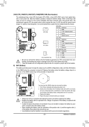
... installed inside the chassis. Definition 1 GND 2 +12V 3 Sense • Be sure to connect fan cables to the fan headers to keep the values (such as BIOS configurations, date, and time information) in the CMOS when the computer is the ground wire). Do not place a jumper cap on the headers. 6) BAT (Battery...
... installed inside the chassis. Definition 1 GND 2 +12V 3 Sense • Be sure to connect fan cables to the fan headers to keep the values (such as BIOS configurations, date, and time information) in the CMOS when the computer is the ground wire). Do not place a jumper cap on the headers. 6) BAT (Battery...
Manual
Page 25
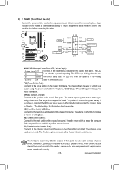
... function requires a chassis with a chassis intrusion switch/sensor. Hardware Installation S1 Blinking tem is detected, the BIOS may issue beeps in S1 sleep state. When connecting your system using the power switch (refer to Chapter 2, "BIOS Setup," "Power Management Setup," for information about beep codes. • HD (Hard Drive Activity LED, Blue...
... function requires a chassis with a chassis intrusion switch/sensor. Hardware Installation S1 Blinking tem is detected, the BIOS may issue beeps in S1 sleep state. When connecting your system using the power switch (refer to Chapter 2, "BIOS Setup," "Power Management Setup," for information about beep codes. • HD (Hard Drive Activity LED, Blue...
Manual
Page 28
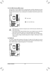
...may cause damage to the motherboard. • After system restart, go to BIOS Setup to load factory defaults (select Load Optimized Defaults) or manually configure the BIOS settings (refer to Chapter 2, "BIOS Setup," for BIOS configurations). 16) PHASE LED The number of lighted LEDs. To enable the Phase... number of lighted LEDs indicates the CPU loading. 14) CLR_CMOS (Clearing CMOS Jumper) Use this jumper to factory defaults. date information and BIOS configurations) and reset the CMOS values to clear the CMOS values (e.g. Open: Normal Short: Clear CMOS Values • Always turn off your...
...may cause damage to the motherboard. • After system restart, go to BIOS Setup to load factory defaults (select Load Optimized Defaults) or manually configure the BIOS settings (refer to Chapter 2, "BIOS Setup," for BIOS configurations). 16) PHASE LED The number of lighted LEDs. To enable the Phase... number of lighted LEDs indicates the CPU loading. 14) CLR_CMOS (Clearing CMOS Jumper) Use this jumper to factory defaults. date information and BIOS configurations) and reset the CMOS values to clear the CMOS values (e.g. Open: Normal Short: Clear CMOS Values • Always turn off your...
Manual
Page 29
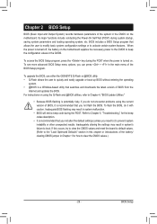
... System) records hardware parameters of the system in system malfunction. • BIOS will emit a beep code during the POST. To upgrade the BIOS, use either the GIGABYTE Q-Flash or @BIOS utility. • Q-Flash allows the user to Chapter 4, "BIOS Update Utilities." • Because BIOS flashing is potentially risky, if you need to) to boot. Its major...
... System) records hardware parameters of the system in system malfunction. • BIOS will emit a beep code during the POST. To upgrade the BIOS, use either the GIGABYTE Q-Flash or @BIOS utility. • Q-Flash allows the user to Chapter 4, "BIOS Update Utilities." • Because BIOS flashing is potentially risky, if you need to) to boot. Its major...

Manual
Page 30
H67A-USB3-B3 E12c . . . . : BIOS Setup : XpressRecovery2 : Boot Menu : Qflash 12/31/2010-H67-7A89UG0WC-00 Function Keys Function Keys: : POST SCREEN Press the key to show the BIOS POST screen at system startup, refer to the instructions on the Full Screen LOGO Show item on BIOS Setup settings. Note: The... having to Xpress Recovery2 during the POST. 2-1 Startup Screen The following screens may appear when the computer boots. To show the BIOS POST screen. BIOS Setup - 30 - The system will still be used for one time only. After system restart, the device boot order will ...
H67A-USB3-B3 E12c . . . . : BIOS Setup : XpressRecovery2 : Boot Menu : Qflash 12/31/2010-H67-7A89UG0WC-00 Function Keys Function Keys: : POST SCREEN Press the key to show the BIOS POST screen at system startup, refer to the instructions on the Full Screen LOGO Show item on BIOS Setup settings. Note: The... having to Xpress Recovery2 during the POST. 2-1 Startup Screen The following screens may appear when the computer boots. To show the BIOS POST screen. BIOS Setup - 30 - The system will still be used for one time only. After system restart, the device boot order will ...
Manual
Page 31
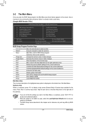
... to display a help screen. Press to exit the help screen (General Help) of function keys available for reference only and may differ by BIOS version. - 31 - BIOS Setup Help for each item is in the Item Help block on the right side of the submenu. • If you do not find... & Exit Setup Exit Without Saving ESC: Quit F8: Q-Flash Select Item F10: Save & Exit Setup Change CPU's Clock & Voltage F11: Save CMOS to BIOS F12: Load CMOS from BIOS BIOS Setup Program Function Keys Move the selection bar to select an item Execute command or enter the submenu Main Menu: Exit the...
... to display a help screen. Press to exit the help screen (General Help) of function keys available for reference only and may differ by BIOS version. - 31 - BIOS Setup Help for each item is in the Item Help block on the right side of the submenu. • If you do not find... & Exit Setup Exit Without Saving ESC: Quit F8: Q-Flash Select Item F10: Save & Exit Setup Change CPU's Clock & Voltage F11: Save CMOS to BIOS F12: Load CMOS from BIOS BIOS Setup Program Function Keys Move the selection bar to select an item Execute command or enter the submenu Main Menu: Exit the...
Manual
Page 32
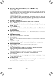
.... MB Intelligent Tweaker(M.I.T.) Use this menu to configure all the changes made in effect. It allows you to view the BIOS settings but not to see information about autodetected system/CPU temperature, system voltage and fan speed, etc. Load Fail-Safe ... or disable password. A supervisor password allows you to restrict access to 8 profiles (Profile 1-8) and name each profile. Pressing to the system and BIOS Setup. It allows you to make changes. Save & Exit Setup Save all the power-saving functions. PC Health Status Use this...
.... MB Intelligent Tweaker(M.I.T.) Use this menu to configure all the changes made in effect. It allows you to view the BIOS settings but not to see information about autodetected system/CPU temperature, system voltage and fan speed, etc. Load Fail-Safe ... or disable password. A supervisor password allows you to restrict access to 8 profiles (Profile 1-8) and name each profile. Pressing to the system and BIOS Setup. It allows you to make changes. Save & Exit Setup Save all the power-saving functions. PC Health Status Use this...
Manual
Page 33
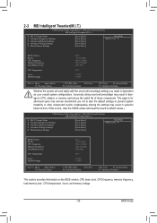
...Miscellaneous Settings [Press Enter] [Press Enter] [Press Enter] [Press Enter] [Press Enter] Item Help Menu Level BIOS Version BCLK CPU Frequency Memory Frequency Total Memory Size CPU Temperature Vcore DRAM Voltage E12c 99.80 MHz 3094.12 MHz 1964.... Settings [Press Enter] [Press Enter] [Press Enter] [Press Enter] [Press Enter] Item Help Menu Level BIOS Version BCLK CPU Frequency Memory Frequency Total Memory Size CPU Temperature Vcore DRAM Voltage E12c 99.80 MHz 3094.12 MHz 1964....
...Miscellaneous Settings [Press Enter] [Press Enter] [Press Enter] [Press Enter] [Press Enter] Item Help Menu Level BIOS Version BCLK CPU Frequency Memory Frequency Total Memory Size CPU Temperature Vcore DRAM Voltage E12c 99.80 MHz 3094.12 MHz 1964.... Settings [Press Enter] [Press Enter] [Press Enter] [Press Enter] [Press Enter] Item Help Menu Level BIOS Version BCLK CPU Frequency Memory Frequency Total Memory Size CPU Temperature Vcore DRAM Voltage E12c 99.80 MHz 3094.12 MHz 1964....
Manual
Page 34
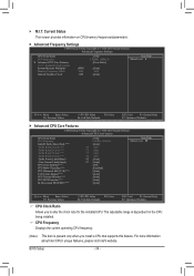
... screen provides information on the CPU being installed. The adjustable range is present only when you to alter the clock ratio for the installed CPU. BIOS Setup - 34 - M.I.T.
... screen provides information on the CPU being installed. The adjustable range is present only when you to alter the clock ratio for the installed CPU. BIOS Setup - 34 - M.I.T.
Manual
Page 35
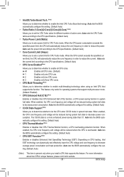
...and effectively lower the CPU voltage and core frequency to decrease average power consumption and heat production. Auto lets the BIOS automatically configure this function. Auto lets the BIOS automatically configure this setting. (Default: Auto) C3/C6 State Support (Note) Allows you install a CPU that ... and voltage will be reduced during system halt state to decrease power consumption. All Enables all CPU cores. Auto lets the BIOS automatically configure this feature. When the CPU power consumption exceeds the specified power limit, the CPU will be reduced during system ...
...and effectively lower the CPU voltage and core frequency to decrease average power consumption and heat production. Auto lets the BIOS automatically configure this function. Auto lets the BIOS automatically configure this setting. (Default: Auto) C3/C6 State Support (Note) Allows you install a CPU that ... and voltage will be reduced during system halt state to decrease power consumption. All Enables all CPU cores. Auto lets the BIOS automatically configure this feature. When the CPU power consumption exceeds the specified power limit, the CPU will be reduced during system ...
Manual
Page 36
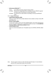
... visit Intel's website. Internal Graphics Clock Allows you to the BCLK/DMI/PEG Frequency(0.1MHz) and System Memory Multiplier settings. BIOS Setup - 36 - Bi-Directional PROCHOT (Note) Auto Lets the BIOS automatically configure this feature. Disabled Only allows the CPU to detect whether an overheating is occurring to emit PROCHOT signals. >>>>> Standard...
... visit Intel's website. Internal Graphics Clock Allows you to the BCLK/DMI/PEG Frequency(0.1MHz) and System Memory Multiplier settings. BIOS Setup - 36 - Bi-Directional PROCHOT (Note) Auto Lets the BIOS automatically configure this feature. Disabled Only allows the CPU to detect whether an overheating is occurring to emit PROCHOT signals. >>>>> Standard...
Manual
Page 37
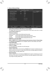
... Interleaving, Rank Interleaving, Channel A Timing Settings, and Channel B Timing Settings items to increase memory performance and stability. Auto lets the BIOS automatically configure this setting. (Default: Auto) - 37 - Enabled allows the system to simultaneously access different ranks of the memory to... Enables or disables memory channel interleaving. Options are synchronous to increase memory performance and stability. BIOS Setup Auto lets the BIOS automatically configure this setting. (Default: Auto) Rank Interleaving Enables or disables memory rank interleaving.
... Interleaving, Rank Interleaving, Channel A Timing Settings, and Channel B Timing Settings items to increase memory performance and stability. Auto lets the BIOS automatically configure this setting. (Default: Auto) - 37 - Enabled allows the system to simultaneously access different ranks of the memory to... Enables or disables memory channel interleaving. Options are synchronous to increase memory performance and stability. BIOS Setup Auto lets the BIOS automatically configure this setting. (Default: Auto) Rank Interleaving Enables or disables memory rank interleaving.
Manual
Page 38
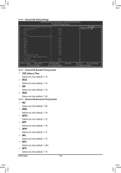
...), 1~15. tRFC Options are : Auto (default), 1~15. tRP Options are : Auto (default), 1~255. tRRD Options are : Auto (default), 1~12. tWL Options are : Auto (default), 1~15. BIOS Setup - 38 - >>>>> Channel A/B Timing Settings CMOS Setup Utility-Copyright (C) 1984-2010 Award Software Channel A Timing Settings >>>>> Channel A Standard Timing Control x CAS Latency Time 7 x tRCD 7 x tRP...
...), 1~15. tRFC Options are : Auto (default), 1~15. tRP Options are : Auto (default), 1~255. tRRD Options are : Auto (default), 1~12. tWL Options are : Auto (default), 1~15. BIOS Setup - 38 - >>>>> Channel A/B Timing Settings CMOS Setup Utility-Copyright (C) 1984-2010 Award Software Channel A Timing Settings >>>>> Channel A Standard Timing Control x CAS Latency Time 7 x tRCD 7 x tRP...


